ISSN(Online): 2320-9801 ISSN (Print) : 2320-9798
I
nternational
J
ournal of
I
nnovative
R
esearch in
C
omputer
and
C
ommunication
E
ngineering
(A High Impact Factor, Monthly, Peer Reviewed Journal)
Website: www.ijircce.com
Vol. 6, Issue 2, February 2018
Design and Analysis of Multiband
Asymmetrical U-Slot Patch Antenna
B. Jyothi1, M. Saranya2
Assistant Professor, Department of ECE, Vijaya Institute of Technology for women, Enikepadu, Vijayawada, India1, 2
ABSTRACT: A multiband U-slot patch antenna, with linear polarization, is designed for WiMAX and WLAN
systems. The impedance bandwidths (dB) of 2.3%, 3.4%, 7.2% and 5.2% were achieved at central frequencies 3.3 GHz, 3.7 GHz, 5.3 GHz and 5.8 GHz, with gains of 5 dBi, 7.3 dBi, 7.5 dBi and 8.2 dBi, respectively. The antenna is designed with coaxial feeding technique and the overall dimension is around 50X50 on FR4 substrate. The simulation results of reflection coefficient, gain, radiation patterns and field distributions are carried and presented in this work with FEM based electromagnetic tool HFSS.
KEYWORDS: Asymmetric, FR4, Multiband, U-Slot, WiMAX, WLAN.
I. INTRODUCTION
Recently, the increasing demand for wireless communication services has stimulated the need for antennas which can operate at more than one frequency band. Multi band antennas are more reliable and required when the reserved place to lay the antenna is too little to fit in. Multiband Antennas are very desirable for current wireless applications as they can cover multiple frequencies using a single antenna. However, fixed multiband antenna usually requires complicated filters with inflexible requirements to improve their out-of-band noise rejection [1-4]. The filter usually bulky and can add complexity to any communication systems. As a solution to these disadvantages, a reconfigurable antenna can achieve a better out of band noise rejection [5-6]. Moreover, modern wireless communication systems relying on multiband reconfigurable antennas are becoming more popular for their ability to serve multiple standards and applications using a single compact antenna allowing a reduction in the dimensions of the wireless device [7-9] and more space to integrate other electronic components. In this article, we proposed a microstrip co-axial fed multiband antenna operating at different frequencies, which includes the wireless communication applications [10-12].
The proposed antenna is operating at multiband, which serves for most of the wireless communication applications and should fit in to the communication module. The design specifications and the modelling are given in the antenna design section.
II. ANTENNA DESIGN
(a) (b) (c)
Fig 1: Antenna Iterations, (a) U-Slot Antenna, (b) Double U-slot antenna, (c) Triple U-slot antenna
ISSN(Online): 2320-9801 ISSN (Print) : 2320-9798
I
nternational
J
ournal of
I
nnovative
R
esearch in
C
omputer
and
C
ommunication
E
ngineering
(A High Impact Factor, Monthly, Peer Reviewed Journal)
Website: www.ijircce.com
Vol. 6, Issue 2, February 2018
III. RESULTS AND DISCUSSION
The coaxial probe usually has a characteristic impedance of 50 ohms. The input impedance of the patch antenna varies with the feed location. Thus, the location of the probe should be at a 50 ohm point of the patch to achieve impedance matching. The reflection coefficient of the designed slot antennas is presented in Fig 3. S11<-10 dB is considered as the operating band and the bandwidth and the dual band characteristics are presented here.
Fig 3: Return loss Vs Frequency of different slot models
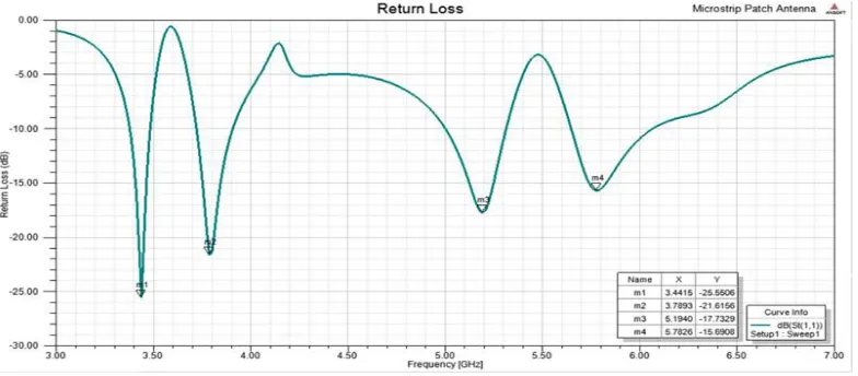
Fig 5: Return loss curve of proposed model
The reflection coefficient of the proposed quad band antenna is presented in Fig 5. The return loss at fundamental resonant frequency is around -25 dB, -21 dB at second resonant frequency, -17 dB at third resonant frequency and -15 dB at fourth band. The smith chart for the designed antenna model is shown in Fig 6. The impedance matching characteristics at resonant frequencies can be observed from the below figure.
ISSN(Online): 2320-9801 ISSN (Print) : 2320-9798
I
nternational
J
ournal of
I
nnovative
R
esearch in
C
omputer
and
C
ommunication
E
ngineering
(A High Impact Factor, Monthly, Peer Reviewed Journal)
Website: www.ijircce.com
Vol. 6, Issue 2, February 2018
Fig 7: Parametric analysis
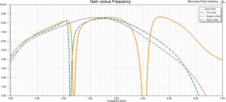
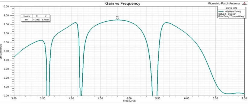
Fig 8: Gain Vs Frequency of proposed model
Fig 9: 3D gain of the antenna
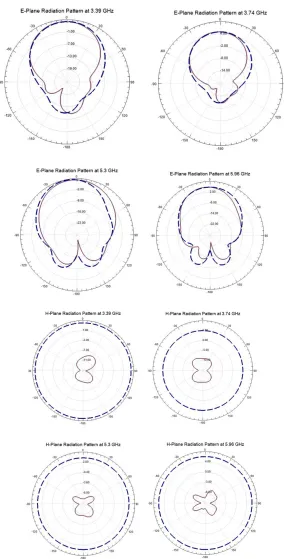
The optimized model radiation pattern is shown in Figure 9 and 10. We observe Omni directional radiation characteristics in the azimuth plane at initial frequency and a directive shaped radiation pattern in the E-Plane. The presence of surface currents originating in the patch is responsible for distorted radiation pattern at operating band. The far fields can be calculated using the equations
The far-fields are
(1)
ISSN(Online): 2320-9801 ISSN (Print) : 2320-9798
I
nternational
J
ournal of
I
nnovative
R
esearch in
C
omputer
and
C
ommunication
E
ngineering
(A High Impact Factor, Monthly, Peer Reviewed Journal)
Website: www.ijircce.com
Vol. 6, Issue 2, February 2018
Fig 11: Current distribution
The current density can be written as
= (x) (y-y’) --- (3)
(x)= --- (4)
It follows that = dx dy = Jd --- (5)
From the figure we observe that the surface current distribution is concentrated along the patch element and along the edge of the feed. Here we do not observe higher order surface currents on the outer element thereby eliminating coupling between the port.
IV. CONCLUSION
A multiband antenna for wireless communication applications is presented in this work. The proposed antenna is providing quad band characteristics with good impedance matching and bandwidth. The designed model is showing directive radiation pattern in E-plane and omni directional pattern in H-Plane. A peak realized gain of more than 8.4 dB is observed in the operating band and in other operating bands antenna is showing good radiation characteristics and directivity. The proposed model is well suitable for future wireless communication applications with stable gain and efficiency.
REFERENCES
ISSN(Online): 2320-9801 ISSN (Print) : 2320-9798
I
nternational
J
ournal of
I
nnovative
R
esearch in
C
omputer
and
C
ommunication
E
ngineering
(A High Impact Factor, Monthly, Peer Reviewed Journal)
Website: www.ijircce.com
Vol. 6, Issue 2, February 2018
[8]D. Ujwala, A. Gnandeep reddy, “Wideband Coaxial Fed Rotated Stacked Patch Antenna for Wireless Applications”, Int. Journal of Engineering Research and Applications ISSN: 2248-9622, Vol. 4, Issue 3, pp.102-105, March 2014
[9] V. Ugendra, Habibulla Khan, B.T.P. Madhav and Ch. Joshna, Multiband Fractal Slot Antenna with Closed Ground Structure, Smart Innovation, Systems and Technologies, Vol 76, pp 75-83, 2017.
[10] M Lavanya, K V Prasanth, B T P Madhav, Compact Printed Elliptical Slotted Antenna For Multiband Applications, International Journal of Pure and Applied Mathematics, Vol 117, No. 19, pp 253-258, 2017.
[11] B. T. P. Madhav, T. V. Rama Krishna, K. Datta Sri Lekha, D. Bhavya, V. S. Dharma Teja, T. Mahender Reddy, T. Anilkumar, Multiband Semicircular Planar Monopole Antenna with Spiral Artificial Magnetic Conductor, Lecture Notes in Electrical Engineering, ISSN: 1876-1100, Vol 471, pp 599-607, 2018.