R E S E A R C H
Open Access
An efficient MIMO scheme with signal space
diversity for future mobile communications
Zhanji Wu
*†and Xiang Gao
†Abstract
An efficient wireless transmission scheme with the signal space diversity (SSD) is proposed to improve the performance of multiple-input multiple-output (MIMO) systems in fading channels. By introducing the rotated modulation and space-time component interleaver, the proposed scheme jointly optimizes channel coding, modulation, and MIMO and can improve the link reliability and energy efficiency. An optimum spatial component interleaver is proposed to maximize the MIMO achievable rate. Based on the average mutual information (AMI)-maximization criterion, the optimal rotation angles of real-valued signal and complex-valued QAM signal are investigated for the MIMO scheme. For the iterative demapping and decoding (ID) scheme, a simple genetic algorithm (GA) to search binary convolution code (BCC) is also put forward to match the rotated modulation. Simulation results show that the optimized
BCC-coded MIMO scheme with SSD-ID outperforms the turbo-coded MIMO scheme with bit-interleaved coded modulation (BICM)-ID by 1.4 dB signal-to-noise ratio (SNR) gain, while the new scheme has much lower complexity. So, the proposed scheme is simple, efficient, and promising for future wireless communication systems.
Keywords: Quadrature amplitude modulation (QAM); Signal space diversity (SSD); Multiple-input multiple-output (MIMO); Iterative demodulation and decoding (ID); Extrinsic information transfer chart (EXIT)
1 Introduction
Wireless communications have made a great progress in the recent few years. By introducing more advanced tech-nology, 5G will provide higher spectral efficiency, more spectrum resources, and more reliability to meet the growing demand for mobile traffic [1].
Bit-interleaved coded modulation (BICM) is a bandwidth-efficient coded modulation scheme which increases the time diversity in fading channels [2,3]. For its iterative version, BICM with iterative demapping and decoding (BICM-ID), the extrinsic information is transferred between the channel decoder and the soft-in-soft-out demapper, which is like the serial turbo decoder. Multiple-input multiple-output (MIMO) scheme is the extension of the coding theory on the space domain, so it is also named space-time coding (STC) [4]. Foschini proposed a layered space-time (LST) architecture to pro-cess multidimensional signals in the space domain [5]. The BICM-LST is a conventional spectral-efficient spatial
*Correspondence: [email protected]
†Equal contributors
School of Telecommunication Engineering, Beijing University of Posts and Telecommunications, Xitucheng Road 10, Beijing, China
multiplexing technology to deal with MIMO fading chan-nels, and the BICM-threaded layered space-time (TLST) with a cyclic-shift spiral spatial interleaver is regarded as the most efficient method, because the cyclic-shift spatial interleaver introduces effective space diversity for the codeword on each layer [6]. In general, the BICM-LST can be viewed as the serial concatenation of the channel coding, modulation, and spatial layered multi-plexing. Because BICM-LST exhibits a robust diversity performance on fading channels, it is widely deployed by wireless communication standards.
As for the bandwidth-efficient quadrature amplitude modulation (QAM), uncoded rotated multidimensional modulation schemes over independent Rayleigh fading channels were studied in [7] for the input single-output (SISO) scheme. Different from the other well-known diversity (time, frequency, code, space), it has an intrinsic modulation diversity, which is named sig-nal space diversity (SSD). Through the combination of constellation rotation and component interleaver, the schemes can achieve very high modulation diversity, and the error performance over fading channels can approach that on the additive white Gaussian noise (AWGN)
channels. SSD schemes for SISO system have been exten-sively researched. In [8], SSD is introduced to the BICM by the means of modifications to the QAM constellation mapper and demapper so as to improve the BICM per-formance of QAM constellations for broadcasting appli-cations. In [9], a LDPC-coded SSD scheme for multi-level modulation was presented. N.F. Kiyani and J.H. Weber studied the rotated-MPSK SISO BICM-ID system [10,12], which focused on two-dimensional multiphase shift key-ing (MPSK) scheme. In [11], the performance analysis of BICM-ID with SSD in fading channels is presented. In [13], the extension of BICM-SSD schemes with a non-binary code was proposed. We also proposed coded orthogonal frequency division multiplexing (OFDM) sys-tems with SSD in [14,15]. In [16], the schemes combin-ing SSD with SISO-coded BICM and BICM-ID systems were investigated. It provided a new criterion for deter-mining the optimal rotation angle by maximizing the average mutual information (AMI). For the optimization of BICM-ID system, it proved that SSD can mitigate the different-slope problem of the demapper’s extrinsic information transfer (EXIT) curve under different chan-nels. However, finding well-matched channel codes for given labeling in BICM-ID system with SSD is still a big challenge.
The combination of signal rotation and space-time coding in MIMO system can effectively improve the diversity gain. In order to achieve full diversity, the quasi-orthogonal space time block codes (QOSTBC) with rotating the constellations of half of the complex sym-bols has been widely discussed in [17-20]. Some specific optimal rotation angles and corresponding optimization criterions for QAM and phase shift keying (PSK) constel-lations are provided. A rotation-based method that aims at maximizing the minimum distance in the space-time constellation is proposed in [17]. The proposed scheme shows good improvement of the codes compared to their non-rotated counterparts. In [18], the authors considered the design of rotated QOSTBC for the MISO system. The code designs are based mainly on the rank and the deter-minant criteria, and the optimal rotation angleπ/6 can provide full diversity and the optimal coding gain. In [19], the authors proposed to design the signal constellations properly to ensure that the resulting quasi-orthogonal STBCs can guarantee to achieve the full diversity. The optimal rotation angles are determined by maximizing the diversity product. A novel method to exactly derive the coding gain of QSTBC as a function of the rota-tion angle and the minimum Euclidean distance of two-dimensional constellations is proposed in [20]. A coded MIMO scheme for block-fading channels was proposed in [21], which consists of a channel code and a space-time code. The space-space-time code is designed based on SSD technique, which allows full spatial multiplexing MIMO
transmission and achieves full space diversity. In [22], the uncoded SSD scheme was extended to V-BLAST MIMO systems in order to achieve the maximum diversity gain without additional power or bandwidth consumption. An improved turbo-coded SSD scheme was proposed for MIMO-OFDM BICM system in [23], and the linear min-imum mean square error (LMMSE) equalization is uti-lized for the non-ID MIMO detection. In general, the research of SSD technique in coded MIMO systems is still on the original stage. There are still many open prob-lems. For instance, the optimal rotation angles in current research mainly depend on the maximum product dis-tance introduced in [7]. Unfortunately, this criterion is only valid for the SISO system in high signal-to-noise ratio (SNR) region. As for the coded MIMO scheme, when powerful forward error-correction codes (FECs) are con-sidered, actual SNR can be quite low. Hence, the angle values applied to uncoded SISO system do not lead to the best error performance for the coded modulation MIMO scheme. What is more, current research works mainly focus on local optimizations. For example, most proposed MIMO systems with SSD are only an extension of SISO-SSD system, and all are based on the conven-tional non-precoding transmitter. The channel coding, QAM modulation, and STC are independent with each other, which is just a straightforward serial concatena-tion. Hence, the performance of the BICM-LST is still rather far away from the MIMO fading channel capacity. For example, a near-capacity BICM-LST scheme was pro-posed in [24], which allows the iterative processing of the list sphere detection (LSD) and turbo decoding, but simu-lation results indicate that the gaps to the MIMO capacity are still more than 2 dB. As each individual optimization becomes mature so far, from the philosophy, it is high time to optimize these key technical elements jointly so as to improve the overall performance.
SNR gain, while the new scheme has much lower com-plexity.
Throughout this paper, we use bold letters to represent vectors or matrices.(·)T and(·)H represent transposition and conjugate transposition, respectively. SNR= Es/N0,
whereEs denotes the average symbol energy per receive antenna and N0 = 2σ2 denotes the variance of the
complex Gaussian noise.
The paper is organized as follows. An improved JCMD MIMO scheme is proposed in Section 2. Theoretical anal-ysis about the achievable rate of JCMD-MIMO for rotated real-valued signals is given in Section 3. Based on the AMI analysis, the optimal rotation angles for JCMD and JCMD-ID MIMO systems are presented in Section 4. Section 5 introduces an outer convolutional code search method for the optimization of JCMD-ID system with optimal rota-tion angle. Simularota-tion results are presented in Secrota-tion 6 on fast fading channels. Concluding remarks are offered in Section 7.
2 System model
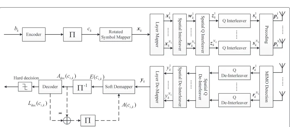
Based on the BICM-TLST scheme, a system model of NL-layer MIMO-JCMD-ID is shown in Figure 1. Perfect channel state information (CSI) is assumed to be known at both the transmitter and the receiver. In Figure 1, the iterative feedback processing is depicted in dashed lines. Without loss of generality, a rank-L NR×NTMIMO sys-tem with L nonzero eigenvalues is assumed, where NR andNT are the number of receive and transmit anten-nas, respectively, and NL ≤ L ≤ min{NR,NT}. In the transmitter,K information bitsB= (b1,b2,. . .,bK)T are encoded and interleaved to yield the coded bit sequence
C=(c1,c2,. . .,cN)T. Afterwards,m-tuple coded bits are mapped to a complex symbolxk=xk(I)+j·xk(Q), which
is chosen from a 2m-ary rotated QAM constellation set
χ = xˆ1,xˆ2,. . .,xˆ2m according to some optimal angle. Each symbolxk has one Q-componentxk(Q)and one I-componentxk(I). The rotated mapped symbol sequence is first mapped onto NL layers in a round robin man-ner. Afterwards, the conventional cyclic-shift spatial inter-leaver of TLST is used for different symbols onNLlayers to exploit both the space and time diversity as the follow-ing, because the cyclic-shift spatial interleaver allows the codewords to be distributed on all layers:
wlk =xik, l=(i+k−2)modNL+1, (1)
wherewlkdenotes thekth(k∈N+)symbol at thelth(l∈ [1,NL])layer after the spatial interleaver, andxik denotes the kth symbol at theith(i ∈[1,NL]) layer before the interleaver. Then, a spatial Q-component interleaver is applied for the Q components ofNLsymbols at the same instant as the following:
znk(Q)=wlk(Q), n=NL−l+1, (2)
whereznk denotes thekth symbol at thenth(n ∈[1,NL]) layer after the spatial Q interleaver. Thus, I components keep the same layer order as before, and just Q compo-nents change the layer order. The spatial Q-component interleaver is used to make the fading of I component and that of the Q component as uncorrelated as possible in the space domain. Thus, the modulation diversity of the proposed scheme is further extended to the spatial dimen-sion. Actually, the Q-component spatial interleaver can be different from the reverse interleaver in Equation 2. For example, it can be a cyclic-shift interleaver as the following,
znk(Q)=wlk(Q), n=(lmodNL)+1. (3)
If perfect CSI is known, we prove that the reverse inter-leaver is better than other interinter-leavers through the later theoretical analysis and computer simulations. If CSI is unknown at the transmitter, the cyclic-shift interleaver in Equation 3 can be used.
In order to make the fading of I component and that of the Q component as uncorrelated as possible in the time domain, after the spatial Q interleaving, Q compo-nents of the mapped symbols in each layer are interleaved through a time-domain pseudo S-random interleaver to
reconstruct a new symbol vectorsk= ponent interleaving. Afterwards, the symbols are mapped ontoNT transmit antennas via the spatial precoding and then transmitted.
The ideal precoding matrix can be obtained by singu-lar value decomposition (SVD), which can divide MIMO channel into parallel independent SISO channels. Accord-ing to the SVD criterion, the NR× NT MIMO channel matrixHkcan be decomposed as
Hk =UkDkVkH, (4)
where theNR×NRmatrixUkand theNT×NTmatrixVk are unitary matrices.Dkis aNR×NT non-negative diag-onal matrix withNL nonzero descending-order singular values,√ρ1 ≥ √ρ2 ≥ . . . ≥ √ρNL > 0, whereρiis the ith largest eigenvalue ofHk·HkH. Thus, the SVD-based linear precoding is performed as the following:
pk=Vk·sk. (5)
In the receiver, the corresponding detection matrix is UHk. The precoding and detection process can be expressed as linear transformations as shown in Equation 6.
denotes the received symbol vector, nk and nk are column vectors of NR complex Gaussian random variables with mean zero and variance
σ2 = N0
2. Thus, due to SVD, the MIMO channel can be
viewed asNL parallel fading channels, and for lth layer, the kth received symbol that corresponds to slk in the transmitter can be expressed as
rkl =√ρl·slk+n l
k. (7)
After the corresponding Q-component de-interleaving in time domain for each layer and spatial Q-component de-interleaving, the kth received symbol on lth layer is reconstructed asylk that corresponds to xlk in the trans-mitter. For ylk, the fading coefficients of I-component
λk(I)and Q-componentλk(Q)are different, which can be expressed as
ylk(I)=λlk(I)xlk(I)+nlk(I)
ylk(Q)=λlk(Q)xlk(Q)+nlk(Q). (8)
Assuming that the Q interleaver is long enough, each coordinate of the symbol after the Q de-interleaving can be regarded as suffering from independent fading coef-ficients. The equivalent coded modulation (CM) channel for JCMD system before sending to the soft demapper can be modeled as
Ykl(η)=lk(η)Xkl(η)+Nkl(η),η∈ {I,Q},l∈[1,NL] , (9)
whereNkl(I)andNkl(Q)are identically independently dis-tributed (i.i.d.) Gaussian noise random variables with zero mean and variance of σ2 = N0
2 . For MIMO fading
channels, lk(I) and lk(Q) are singular values of cor-responding sub-channels. This is in net contrast with respect to SISO scheme where the fading coefficients are Rayleigh distributed. That means the modulation diversity of proposed scheme is further extended to the spatial dimension. By denoting X = X1,. . .,XNL nal matrix, the channel model in Equation 9 can be written in the matrix form as Y = X+ N, where
After that, symbols on multiple layers are reassem-bled as symbol streams y = y1,y2· · ·
T
through the layer demapping. A serial concatenation of a soft-in-soft-out rotated symbol demapper and a channel decoder are employed to approach the maximum likelihood (ML) receiver performance. For JCMD-ID, the iterative demap-ping and decoding scheme is an application of the turbo decoder principle. The soft demapper calculates the extrinsic valueE(ci,k)of bitci,kwhich corresponds to the
E(ci,k)=ln fading channel, the conditional probability is given by
P(yk|xk= ˆx)=
To the complexity, by applying Max-Log-MAP algo-rithm, Equation 11 can be simplified as
E(ci,k)= max
For the JCMD system without the iterative demap-ping and decoding, A(ci,k) = 0. Finally, the decoder can utilize the extrinsic values to decode information bits.
In the transmitter, compared with the conventional BICM, the JCMD scheme introduces extra constella-tion rotaconstella-tion and Q-component interleavers. Constella-tion rotaConstella-tion does not increase the complexity, because the rotated symbol mapping can be implemented through look-up table operations as the same as the conventional modulation without rotation. Q-component interleavers also can be implemented by the low-complexity index-based look-up table operations.
In the receiver, the soft rotated demapping operation of JCMD system is the same as that of BICM system, which is shown in Equation 11. Q-component de-interleavers also can be implemented by the simple reverse index-based look-up table operations.
3 Theoretical analysis of the achievable rate for rotated real-valued signals
Firstly, since real-valued signals are elementary, we ana-lyze the real-valued transmit signals in MIMO systems.
Lemma 1.For any constant rank-2 MIMO fading chan-nel with real-valued transmit signals, the constant achiev-able rate of JCMD-MIMO is not less than that of BICM-MIMO with the conventional uniform power allocation. If and only if the constant eigenvalues are identical, both of them are equal, otherwise the former is greater than the latter.
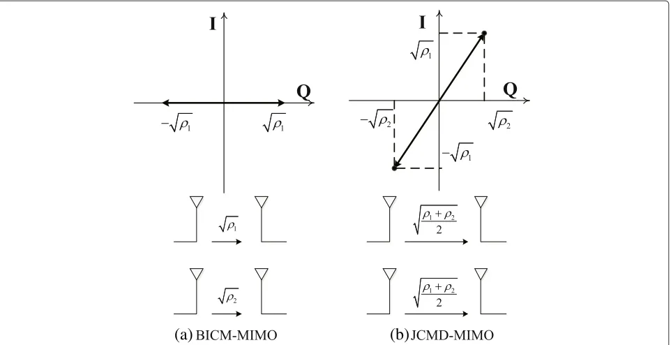
Proof.A simple rank-2 MIMO case with two eigen-values ρ1 and ρ2 is illustrated in Figure 2. Due to the
well-known SVD, BICM-MIMO can be viewed as two parallel fading channels with two eigenvaluesρ1andρ2
for spatial layer 1 and layer 2, respectively. Two fading amplitude coefficients of layer 1 and layer 2 are the cor-responding singular values√ρ1and√ρ2, respectively, as
shown in the left half of Figure 2. Thus, given the same transmit power P2 on each layer for one real-valued sym-bol, the received symbol power of layer 1 and that of layer 2 are ρ1P
2 andρ2
P
2 , respectively, wherePis the total
transmit power for two layers. So, according to Shannon’s theory, the achievable rate of BICM-MIMO is shown as the following:
whereWis the channel bandwidth,σ2is the variance of AWGN. As we know, in order to achieve the capacity in the Equation 14, the transmit signals should be Gaussian distributed. Note that the rotation does not change the achievable rate for the BICM-MIMO scheme without the I/Q-component interleaver.
For the JCMD-MIMO scheme, we consider the π4 -rotated real-valued transmit signal, which is -rotated byπ4 compared with the conventional real-valued signal. Due to the orthogonal modulation, the transmit powers of I com-ponent and that of Q comcom-ponent on each layer are both
P
4. For JCMD-MIMO, after the spatial Q-component
de-interleaver at the receiver, the fading amplitude coefficient of I component is different from that of Q component in one symbol, that is to say, one is√ρ1, and another is√ρ2.
Thus, the received power of I component is also differ-ent from that of Q compondiffer-ent, that is to say, one is ρ1P
4 ,
and another is ρ2P
4 . So, the total received symbol power is
(ρ1+ρ2)P
4 both for layer 1 and layer 2. Thus, JCMD-MIMO
can be viewed as two parallel fading channels with
iden-tical fading amplitude coefficient
ρ1+ρ2
2 for both layer 1
(a)
(b)
Figure 2Achievable rates of conventional BICM-MIMO and JCMD-MIMO system. (a) BICM-MIMO can be viewed as two parallel fading channels
with two eigenvaluesρ1andρ2. (b) JCMD-MIMO can be viewed as two parallel fading channels with identical fading amplitude coefficient
ρ1+ρ2
2
for both layers.
(ρ1+ρ2)P
4 . Therefore, the achievable rate of JCMD-MIMO
is shown as the following:
C2=
W 2 ·log2
1+(ρ1+ρ2) 4σ2 P
2
= W
2 ·log2
1+ρ1+ρ2 2σ2 P+
(ρ1+ρ2)2
16σ4 P 2
.
(15)
So, comparing Equation 14 with 15, it is easy to come to the conclusion:C2≥C1
If and only ifρ2=ρ1,C2=C1.
Furthermore, we will prove thatπ4 is the optimum rota-tion angle for real-valued transmit signals in the JCMD-MIMO scheme. Let us consider a generalθ-rotated real-valued transmit signal, which is rotated by θ compared with the conventional real-valued signal. Thus, the trans-mit power of I component and that of Q component on layer 1 are P2cos2θ and P
2sin2θ, respectively, and the
total transmit power on layer 1 is also P2. Therefore, the received power of I component and that of Q component are ρ2P
2 cos2θ and
ρ1P
2 sin2θ, respectively. So, the total
received symbol power on layer 1 is (ρ1sin2θ+ρ2cos2θ)
2 P.
Likewise, the total received symbol power on layer 2 is
(ρ2sin2θ+ρ1cos2θ)
2 P. Thus, we can get the following
achiev-able rate:
C(θ)=W
2·log2
1+
ρ1sin2θ+ρ2cos2θ
2σ2 P·
1+
ρ1cos2θ+ρ2sin2θ
2σ2 P
!
=W
2 ·log2
1+ρ1+ρ2 2σ2 P+
" ρ1ρ2+
sin2(2θ)(ρ 1−ρ2)2
4
# P2
4σ4 .
(16)
Obviously, whenθ =0, the achievable rate is minimum as Equation 14; and whenθ = π4, the achievable rate is maximum as Equation 15.
According to Lemma 1, we can come to the following theorem:
Theorem 1.For any actual rank-2 MIMO fading chan-nel with real-valued transmit signals, the ergodic achiev-able rate of JCMD-MIMO is greater than that of BICM-MIMO with the conventional uniform power allocation.
than that of BICM-MIMO with the conventional uniform power allocation.
Generally speaking, assuming a rank-L MIMO with a descending-order eigenvalue vectorρ¯ = {ρ1,ρ2,. . .,ρL}, Q-component interleaver only changes the order of Q components onLlayers to another eigenvalue vectorζ¯ = {ζ1,ζ2,. . .,ζL}, whereζ¯is just another arrangement order ofρ¯corresponding to the output order of Q-component spatial interleaver. Hence, due to the orthogonal modu-lation, JCMD-MIMO can be viewed asLparallel fading channels with an eigenvalue vector υ¯ = ρ¯+¯2ζ. So, the achievable rate of rank-LJCMD-MIMO is shown as the following:
wherePis the total transmit power forLlayers. Hence, the optimum problem of the achievable rate is to find the opti-mumζ¯so as to maximizeCL. We can reach the following theorem:
Theorem 2.To maximize the achievable rate of rank-L JCMD-MIMO with a descending-order eigenvalue vector
¯
ρ = {ρ1,ρ2,. . .,ρL}, the optimum Q-component inter-leaver vector ω = {ρL,ρL−1,. . .,ρ1}, that is to say, ω
should be in ascending order, which is just in reverse order ofρ¯.
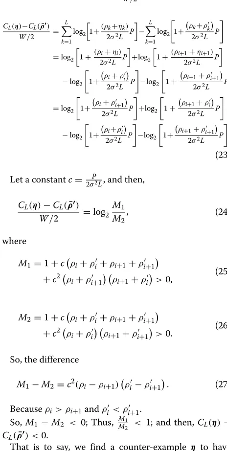
Proof.Assuming someone claims to find a non-increasing-order vector ρ¯ other than ω to have maximum achievable rate CL(ρ¯), we must
That is to say, we find a counter-example η to have more achievable rate thanCL(ρ¯), which contradicts the assumption of maximum achievable rate CL(ρ¯). There-fore, ω should be in ascending order, which is just in reverse order ofρ¯.
So, in Section 2, the reverse Q-component spatial inter-leaver is applied as Equation 2 so as to have the maximum achievable rate. In fact, ifLis an even number, the rank-L JCMD-MIMO with the reverse Q-component spatial interleaver can be viewed as L2 parallel pairs of rank-2 JCMD-MIMO with eigenvalues {ρi,ρL+1−i}, where i ∈
1,L2. Likewise, ifLis an odd number, it can be viewed as the parallel combination of one SISO fading channel with eigenvalue Thus, the largest eigenvalue layer couples with the small-est eigenvalue layer, the second largsmall-est eigenvalue layer couples with the second smallest eigenvalue layer, and so on. Actually, BICM-MIMO is also one special case of JCMD-MIMO whenζ¯ = ¯ρ.
Theorem 3.As for the achievable rate of a rank-L JCMD-MIMO with a descending-order eigenvalue vector
¯
ρ = {ρ1,ρ2,. . .,ρL}, the upper bound is CL(ω), where
ω is in reverse order of ρ¯, and the lower bound is the BICM-MIMO achievable rateCL(ρ¯).
Proof.According to Theorem 2, the maximum achiev-able rate isCL(ω¯), we can getC ≤ CL(ω¯). In addition, CL(ρ¯) is the minimum achievable rate, which can be proved by the similar math skill as follows.
vectorη = ρ1,ρ2,. . .,ρi−1,ρi+1,ρi,ρi+2,. . .,ρL, which
That is to say, we find a counter-example η to have small achievable rate thanCL(ρ¯), which contradicts the assumption of minimum achievable rate CL(ρ¯). There-fore,CL(ρ¯)is the minimum achievable rate.
4 AMI analysis for complex-valued QAM signals For practical communication systems, the transmit signal
Xusually belongs to a finite alphabet (constellation sig-nal set), such as the complex-valued QAM sigsig-nal. AMI also varies with the rotation angle of QAM signals in the MIMO system. Assuming equiprobable QAM constella-tion inputs and the independent Rayleigh fading channel, the AMI of the coded modulation (CM) MIMO system
before the demapper is called CM-AMI, which is irrele-vant to the labeling and defined as [2]
ICM=I(X;Y|)
The AMI after the demapper is called BICM-AMI, which is relevant to the labeling and defined as [2]
IBICM=
AMI analysis is an effective method to calculate its achievable rate. From Equation 28, because I(X;Y|)is independent from labeling, it implies that the AMI of CM system is not related to the labeling. However, for the BICM system, the BICM-AMI strongly depends on the labeling. Extensive literature has proven that Gray label-ing is optimal for the non-ID BICM system in the AWGN channel [25]. Monte Carlo simulation techniques are use-ful tools to get the expectation of a complex function by ergodicity of the random variables [26]. The expecta-tion operaexpecta-tions in Equaexpecta-tions 28 and 29 can be evaluated by using the Monte Carlo simulation techniques. Based on Equation 9, we can get the received symbol before the soft demapper by generating the random coded bits ck (corresponding to the modulated symbol xlk on each layer), the random fading coefficient λlk (SVD of i.i.d. Rayleigh-distributed random channel matrixHk), and the i.i.d. Gaussian noise random variablenlk. Thus, by using the Monte Carlo simulation techniques, we can estimate the expectation values of Equations 28 and 29 by ergod-icity of (ck,Hk, nlk), where P(yl|xl,λl) can be calculated as Equation 12. As for complex-valued QAM signals, the optimum rotation angle usually is different from the value of the real-valued signals, and we can get it by maximizing AMI.
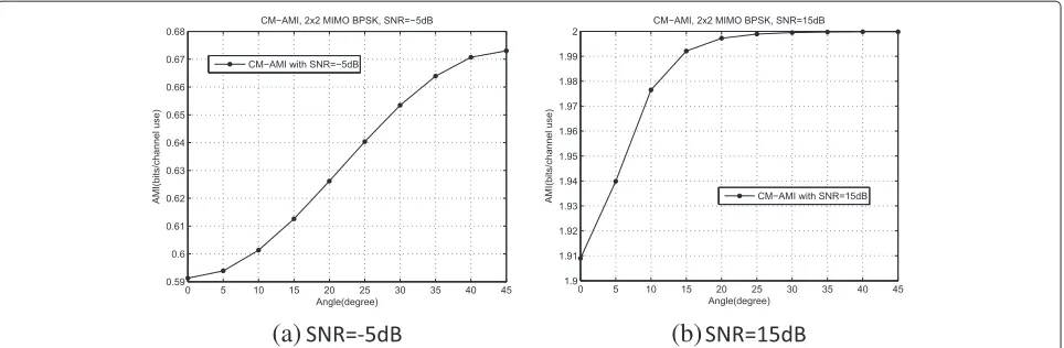
Figure 3 shows how 2×2 MIMO CM-AMI varies with the rotation angleθfor real-valued binary phase shift key-ing (BPSK) symbols. SinceI(X;Y|) = I(Ck;Y|), the ICM andIBICMare the same for BPSK. Both for low and
(a)
(b)
Figure 32×2 MIMO CM-AMIICMvs. rotation angleθfor BPSK over Rayleigh fading channels. (a) SNR= −5 dB. (b) SNR=15 dB.
Figures 4 and 5 show how 4 × 4 MIMO CM-AMI and BICM-AMI vary with the rotation angleθ for QPSK and 16QAM, respectively. The AMIs of proposed sys-tems with two kinds of spatial Q-component interleavers (reverse and cyclic-shift) are plotted in the same figures. Examples of low SNR and high SNR are presented. In Figures 4 and 5, for both spatial Q interleaving algorithms, the optimal rotation angles just have slight difference in high SNR. For CM-AMI, the optimal angle of QPSK at SNR= −3 dB is 45°, while the optimal angle at SNR= 11 dB is about 30° and 29° for the cyclic-shift interleaver and the reverse interleaver, respectively. For BICM-AMI, the optimal angle of QPSK at SNR= −3 dB is 0°, while the optimal angle at SNR= 11 dB is about 26° and 27° for the cyclic-shift interleaver and the reverse interleaver, respectively.
Based on the AMI maximization criterion, the optimal angle corresponds to the maximum AMI value. Figure 6 shows the CM-AMI and BICM-AMI curves that corre-spond to the optimal angles in Figures 4 and 5 for 4×4
MIMO systems. In Figure 6, CM-AMI and BICM-AMI for the reverse interleaver described in Equation 2 are always not less than that of the cyclic-shift interleaver described in Equation 3 both for QPSK and 16QAM. These observations concide well with Theorem 2.
Based on maximizing AMI, we can also obtain the rela-tionship between optimal angle and SNR. The optimal angles for CM and BICM systems vary with SNR for QPSK and 16QAM, which is plotted in Figure 7. The optimal rotation angle of CM is always bigger than that of BICM. When SNR increases, the optimal angle of CM becomes smaller, but the optimal angle of BICM becomes bigger.
For a given modulation order m, according to the AMI valueI corresponding to optimal rotation angle in Figure 6, the optimal code rate for a given SNR can be calculated asR = m·IN
L. Therefore, we can get the rela-tionship between the optimal code rateRand SNR, which is shown in Figure 8.
Thus, for a given operating SNR, we can obtain the optimum rotation angle in Figure 7 and the optimal
(a)
(b)
(a)
(b)
Figure 54×4 MIMO CM-AMIICMand BICM-AMIIBICMvs. rotation angleθfor 16QAM over Rayleigh fading channels. (a) SNR= −3 dB. (b) SNR=11 dB.
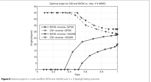
code rate in Figure 8. Furthermore, we can get the relationship between code rate R and optimal rota-tion angle, which is shown in Figure 9 for QPSK and 16QAM. It provides a good reference to select an opti-mal rotation angle for a given code rate. For instance, for code rate = 0.5, the optimal angles for 4× 4 MIMO-BICM QPSK and 16QAM are 18° and 0°, respectively. According to Figures 7 and 9, at low SNR or low code rate, non-rotation is the best for BICM, which implies that the channel coding dominates the BICM perfor-mance, while 45° rotation is the best for CM, which indicates that the rotation symmetry affects the CM per-formance. However, at high SNR or high code rate, the signal space diversity dominates the performance both for
BICM and CM, so BICM-AMI can approach CM-AMI, and the optimum angle of BICM with the optimum reverse spatial interleaver is also close to that of CM with the same interleaver. Note that the rotation angle is just related to the code rate and modulation. So, in practice, the rotation symbol mapper can be implemented through a look-up table that is calculated and stored in advance for a given modulation order and code rate, which is the same as the conventional symbol mapper. Hence, it does not introduce additional processing complexity and delay.
5 Code design for JCMD-ID system
For the non-ID BICM system, Gray mapping has been proved to be optimal. Based on the optimal rotation angle
−5 0 5 10 15 20 25
0 2 4 6 8 10 12 14 16
CM−AMI and BICM−AMI for optimal angle, 4x4 MIMO
SNR(dB)
AMI(bits/channel use)
BICM−cyclic−shift−QPSK BICM−reverse−QPSK CM−cyclic−shift−QPSK CM−reverse−QPSK BICM−cyclic−shift−16QAM BICM−reverse−16QAM CM−cyclic−shift−16QAM CM−reverse−16QAM
−5 0 5 10 15 20 25 0
5 10 15 20 25 30 35 40 45
Optimal angle for CM and BICM vs. SNR, 4*4 MIMO
SNR(dB)
Angle(degree)
BICM−reverse−QPSK CM−reverse−QPSK BICM−reverse−16QAM CM−reverse−16QAM
Figure 7Optimal angleθvs. SNR for QPSK and 16QAM over 4×4 Rayleigh fading channels.
obtained by maximizing BICM-AMI and Gray mapping, the non-ID JCMD system only needs to consider the optimization of channel codes to achieve excellent per-formance. For the JCMD-ID system, besides the optimal rotation angle, it is also very crucial to choose a pair of a well-matched labeling and an outer channel code by some joint optimization.
The convergence behavior of the iterative demodula-tion and decoding can be analyzed by the EXIT chart method, which can describe the flow of extrinsic informa-tion between the demodulator and the decoder [27-29]. Several advantages of EXIT charts are summarized in [29]. The inputs to the demapper are the noise-corrupted chan-nel observations and the a priori knowledge A(ck) on
−5 0 5 10 15 20 25
0 0.1 0.2 0.3 0.4 0.5 0.6 0.7 0.8 0.9 1
Reference code rate vs. SNR, 4*4 MIMO
SNR(dB)
Rate
BICM−reverse−QPSK CM−reverse−QPSK BICM−reverse−16QAM CM−reverse−16QAM
0 0.2 0.4 0.6 0.8 1 0
5 10 15 20 25 30 35 40 45 50
Optimal angle for CM and BICM vs. rate, 4*4 MIMO
Rate
Angle(degree)
BICM−reverse−QPSK CM−reverse−QPSK BICM−reverse−16QAM CM−reverse−16QAM
Figure 9Optimal angleθvs. code rateRfor QPSK and 16QAM over 4×4 Rayleigh fading channels.
the unmapped bits. The demapper outputs channel and extrinsic information E(ck). According to Equations 12 and 19 in [27], the mutual informationIA1=I(ck;A(ck)) (0 ≤ IA1 ≤ 1) between transmitted unmapped bits and
theL-valuesA(ck)can be written as
IA1=
1 2
$
x=−1,1
/ ∞
−∞pA(ck)(ξ|ck=x)·log2
× 2pA(ck)(ξ|ck =x)
pA(ck)(ξ|ck = −1)+pA(ck)(ξ|ck =1) dξ.
(30)
The mutual informationIE1= I(ck;E(ck))(0≤IE1≤1)
can be written as
IE1=
1 2
$
x=−1,1
/ ∞
−∞pE(ck)(ξ|ck=x)·log2
× 2pE(ck)(ξ|ck=x)
pE(ck)(ξ|ck = −1)+pE(ck)(ξ|ck=1)dξ. (31)
In [27], it turns out that thea prioriinputA(ck)is almost Gaussian distributed. Additionally, large interleavers keep the a prioriL-valuesA(ck)fairly uncorrelated over many iterations. Hence, it seems appropriate to model the a prioriinputA(ck)by applying an independent Gaussian random variable with variance σA21 and mean zero (see Equations 1 to 10 in [27]). Thus, the conditional probabil-ity densprobabil-ity function can be written as
pA(ck)(ξ|ck=x)= 1 √
2πσA1
exp ⎡ ⎢ ⎢ ⎢ ⎣−
ξ−σA21
2 x
2
2σA21 ⎤ ⎥ ⎥ ⎥ ⎦
(32)
The mutual information IE1 = I(ck;E(ck)) can be viewed as a function ofIA1, SNR, and the rotation angleθ,
i.e,
IE1 =T1(IA1,SNR,θ). (33)
The functionT1can not be expressed in a closed form.
For a given value of the input mutual informationIA1 =
I(ck;A(ck))(0 ≤ IA1 ≤ 1) to the demodulator, to
com-puteT1(IA1,SNR,θ), the distributionspE(ck)(ξ|ck=x)are most conveniently determined by the Monte Carlo sim-ulation (histogram measurements) proposed in [27,28]. The convenient method has been verified to allow an accurate prediction of the SNR-decoding threshold with low complexity [27].
On the other hand, the extrinsic transfer characteristics of the decoder can describe the input/output relationship between the inputIA2and the outputIE2, which is
inde-pendent of SNR value. It can be computed by assuming thea prioriinput to be Gaussian distributed and applying the same method as used for the demapper characteristic T1. Therefore, the transfer characteristic of the decoder is
denoted by
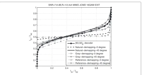
Qiuliang et al. [16] verified that the SSD technique can affect the demapper’s EXIT curve for the SISO BICM-ID SSD system. For the MIMO system, we analyze the effect of the SSD technique to different demapper labelings. Dif-ferent 16QAM labelings (natural, Gray, and reference [16]) are shown in Figure 10. For the 1/2-rate coded 16QAM 4× 4 MIMO system, the corresponding 16QAM EXIT curves with 45° rotation and non-rotation are depicted in Figure 11. The doping technique is used for error-floor removal [30] and the doping rate P = 100. For Natural and Gray labelings, the demappers’ EXIT curves with rotation have a larger slope than that without rota-tion. For the referenced labeling, the demapper’s EXIT curve with rotation is always above the curve without rotation.
Demapper-matched code design is very crucial for the JCMD-ID MIMO system with rotation. In order to approach the capacity, based on EXIT chart, we pro-pose an optimization method of outer channel codes to match with a given demapper for the JCMD-ID system. We choose the BCC as the channel code. For a given SNR, if two EXIT curves of the demapper and the decoder do not intersect, the iterative decoding can converge, other-wise it cannot converge. Thus, the SNR which makes the two EXIT curves tangent is the SNR convergence thresh-old, which is also called pinch-off SNR. The objective of JCMD-ID optimization is to find the outer channel code that has the lowest SNR convergence threshold to match with the demapper.
We define the optimization function as follows.
α(G(NReg),SNR)= min
In∈[0,1],n=1,2,...,Num
T1(In)−T2−1(In)
,
(35)
SNR=arg min
SNR
αGNReg , SNR >0
, (36)
whereG(NReg)denotes the generator polynomial of BCC
withNReg registers. Num is the number of selected
sta-tistical samples. SNR is the pinch-off SNR. For N1
out rate
BCC, the objective is to find the optimum GOpt.(NReg)
with the lowest pinch-off SNR from 2NReg+1−1 Nout
generator polynomial candidates. However, the exhaus-tive searching of a channel code to well match the demapper’s EXIT curve is trivial, especially for NReg is
large.
GA is an efficient optimization algorithm, which is stochastic search techniques based on the mechanism of natural selection and natural genetics [31]. In GA, a genetic representation is required for the individuals in a population. Generator polynomials of BCCG(NReg) =
g1,g2,. . .,gNout
2inherently provides a(NReg+1)×Nout
-length binary string Sg =< g1,g2,. . .,gNout >. gi is
the (NReg +1)-length binary generator polynomial
cor-responding toith(1 ≤ i ≤ Nout)output. Based on the
genetic algorithm, an optimization method is proposed as follows.
Step 1:Initial population. Set the current iterative number (number of generations)Npop=0, the number of candidate generator polynomials
(population size)Ng, the maximum iterative number Nmax, crossover probabilityPc, and mutation probabilityPm.Ngbinary strings
Sig=<gi1,gi2,. . .,giNout >that correspond to the candidate polynomials are randomly initialized, which are denoted by a setCNpop, where gi1,gi2,. . .,giNout ∈1, 2NReg+1 ,1≤i≤N
g. Step 2:Selection. Reduce the SNR by small steps
SNR(e.g., 0.1 dB) and compute the pinch-off SNRs SNRiof all the candidate generator polynomials Gi(NReg)=
gi1,gi2,. . .,giNout
2in population, where <gi1,gi2,. . .,giNout>∈CNpop, 1≤i≤N
g. We use the pinch-off SNR to measure the fitness. The fitness function is associated with the maximum pinch-off SNR SNRmax= max
1≤i≤Ng &
SNRi '
, shown as
f
Sig
=SNRmax(dB)+0.1−SNRi(dB). (37)
(a) (b) (c)
0 0.2 0.4 0.6 0.8 1 0
0.1 0.2 0.3 0.4 0.5 0.6 0.7 0.8 0.9 1
SNR=7.8 dB,R=1/2,4x4 MIMO JCMD 16QAM EXIT
I A1 / IE2 I E1
/ I
A2
[63,32]
8−decoder
Natural−demapping−0 degree Natural−demapping−45 degree Gray−demapping−0 degree Gray−demapping−45 degree Reference−demapping−0 degree Reference−demapping−45 degree
Figure 11EXIT chart analysis for 16QAM at SNR=7.8 dB.
Ngindividuals are selected to breed a new generation with probability proportional to the fitness value.
The probability thatSigis selected isP(i)= f
Sig
Ng
k=1
f
Skg
.
Based on roulette wheel selection (RWS) algorithm, thetth(1≤t≤Ng)individual selection follows the steps below.
A. Generate a uniform random numberχ(t),
χ(t)∈[0, 1].
B. Ifk−1 i=0
P(i)≤χ(t) < k i=1
P(i)(1≤k≤Ng),
P(0)=0,Skgis selected.
Step 3:Crossover. For two adjacent selected individuals, a random numberκcfrom the range [ 0, 1]is generated. Only whenκc<Pc, the crossover operator is carried out. The crossover point is selected randomly. All bits beyond that point in either string are swapped between the two parent individuals, and then two children individuals are obtained.
Step 4:Mutation. For each individuals, a random numberκmfrom the range[0, 1]is generated. Only whenκm<Pm, the mutation operator is carried out through one bit flip at random mutation position.
Step 5:Judgment.Npop=Npop+1. After step 2∼4, a new populationCNpop+1is formed. If
Npop<Nmax, then go to step 2, otherwise stop. The
generator polynomial with the lowest pinch-off SNR inCNpop+1is chosen as the optimum one.
Using the method above, a rate-half BCC code with NReg = 5 is optimized for the natural labeling 16QAM
JCMD-ID system. Based on the AMI analysis in Section 4, the optimal rotation angle for 0.5 rate 16QAM JCMD-ID system is 45°. The optimal generator polynomial is [63,32]8. As shown in Figure 11, the natural labeling
demapper’s EXIT curve with 45° rotation keeps a nar-row open tunnel with that of BCC decoder, while its non-rotation curve intersects with the decoder, which shows the effect of rotation to the ID system. The other two labeling demappers’ EXIT curves with and with-out rotation always intersects with the decoder, so the Gray and reference labelings are not suitable for the BCC decoder. Therefore, the natural labeling with 45° rotation matches well with the [63,32]8BCC code and has the best
performance.
6 Simulation result
6.1 Results of non-ID JCMD system on fast fading channels
−3 −2 −1 0 1 2 3 4
10−8
10−7
10−6
10−5
10−4
10−3
10−2
10−1
SNR(dB)
BER
BPSK, DVB−T2 LDPC coded JCMD scheme, 4*4 MIMO, 1/2 Rate, N=64800
4*4−Gaussian input Shannon limit JCMD limit−0 degree
JCMD limit−45 degree JCMD−0 degree JCMD−45 degree−reverse JCMD−45 degree−cyclic−shift
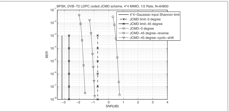
Figure 12BER performance of rate-1/2 DVB-T2 LDPC coded, BPSK 4×4 JCMD MIMO systems on fast fading channels.
Figure 12 shows the bit error rate (BER) performance comparisons of rate-1/2 LDPC-coded BPSK MIMO sys-tems on the independent fast Rayleigh fading channel. The channel fading coefficients on each symbol are indepen-dent iindepen-dentical distributed Rayleigh random variables with the variance 1. BPSK is also a simple real-valued signal,
so the optimal rotation angle is chosen as 45°. For 4×4 MIMO systems, JCMD with 45° rotation obtains signifi-cant SNR gains as compared with JCMD without rotation. For the target BER=10−5, it can achieve 2.2 dB SNR gain. Note that the spatial interleaver, spatial Q-component interleaver, and time Q-component interleaver are all
2 4 6 8 10 12 14 16
10−7 10−6 10−5 10−4 10−3 10−2 10−1
SNR(dB)
BER
QPSK, DVB−T2 LDPC coded JCMD scheme, 4*4 MIMO, N=64800
Gaussian input Shannon limit−1/2 Rate Gaussian input Shannon limit−3/4 Rate JCMD limit−1/2 Rate−18 degree JCMD limit−1/2 Rate−0 degree JCMD limit−3/4 Rate−25 degree JCMD limit−3/4 Rate−0 degree JCMD−1/2 Rate−0 degree−reverse JCMD−1/2 Rate−18 degree−reverse JCMD−1/2 Rate−18 degree−cyclic shift BICM−1/2 Rate
JCMD−3/4 Rate−0 degree−reverse JCMD−3/4 Rate−25 degree−reverse JCMD−3/4 Rate−25 degree−cyclic shift BICM−3/4 Rate
1/2 Rate 3/4 Rate
Table 1 SNR gains and gaps to the capacity for JCMD 4×4 MIMO systems
Parameters Gains compared with Gaps to the JCMD/Gaussian
BICM system (dB) input Shannon limit (dB)
BPSK, 1/2-rate 2.2 1.0/1.5
QPSK, 1/2-rate 0.6 1.1/1.9
QPSK, 3/4-rate 3.9 0.7/2.3
implemented in both JCMD scheme with and without rotation. That means the performance gain of JCMD does not exactly come from the interleavers compared with BICM scheme. We can still obtain significant gain through the optimal rotation and the matching of channel coding and labeling. Furthermore, the 4×4 JCMD MIMO system with the reverse spatial Q interleaver can obtain about 0.6 dB SNR gain compared with that with the cyclic-shift spa-tial Q interleaver. The results coincide well with the above analysis in Section 3.
For the QPSK 4×4 MIMO system, the optimal angles for 1/2 and 3/4 rate are 18° and 25°, respectively. As shown in Figure 13, JCMD systems with the optimal rotation angle can obtain 0.6 and 3.9 dB SNR gains compared with the conventional BICM systems employing the ideal SVD pre-coding for low rate 1/2 and high rate 3/4, respectively. Given the optimal rotation angle, JCMD-MIMO with the reverse interleaver obtains significant 0.3 and 1.3 dB SNR
gains at BER = 10−5 compared to that with the cyclic-shift interleaver for the code rate 1/2 and 3/4, respectively. Meanwhile, the proposed 1/2 rate JCMD system with the reverse interleaver is only about 1.1 dB SNR gap to the JCMD limit for 4 × 4 MIMO. For the 3/4 rate JCMD MIMO, the gap to the JCMD limit is reduced to 0.7 dB for 4×4 MIMO. SNR gains and gaps are summarized in Table 1. From the results, SNR gain becomes bigger for higher code rate.
6.2 Results of JCMD-ID system on fast fading channels For the JCMD-ID 16QAM MIMO system, the optimal rotation angle is obtained by maximizing CM-AMI in Figure 9, and it is 45° at 1/2 rate for 4×4 MIMO sys-tems. In order to confirm our optimization method for JCMD-ID MIMO system, simulations are carried out with proposed [63,32]8BCC-coded JCMD-ID scheme on fast
fading channels for 4× 4 MIMO systems. The size of coded block N = 64, 800 bits and the maximal global iterative number is 30. The powerful 1/2 rate DVB-T2 LDPC-coded Gray-labeling BICM and BICM-ID schemes with the same block size are also simulated as the refer-ence, and the same ideal SVD precoding method is used for the conventional BICM and BICM-ID schemes and the proposed JCMD-ID scheme.
The BER performance comparisons are shown in Figure 14.
7 8 9 10 11 12 13 14
10−7 10−6 10−5 10−4 10−3 10−2 10−1
SNR(dB)
BER
4*4 MIMO, 16QAM, BCC coded JCMD−ID scheme, 1/2 rate, N=64800 Gaussian input Shannon limit JCMD−ID limit−45 deg. JCMD−ID limit−0 deg. BICM limit [63 32]
8−JCMD−ID−0 deg.−Natural−reverse
[63 32]8−JCMD−ID−45 deg.−Natural−reverse [63 32]8−JCMD−ID−45 deg.−Natural−cyclic [63 32]8−BICM−ID−Natural
BICM−LDPC−0 deg.−Gray BICM−ID−LDPC−0 deg.−Gray Reference−LSD
Table 2 Average decoding complexity for each information bit
Operation Optimized BCC Turbo used in [24] DVB-T2 LDPC
Additions 331 816 997.5
Max ops. 158 288 0
Look-ups 0 0 735
For the 4×4 MIMO system with natural labeling, the optimized BCC [63,32]8 coded JCMD-ID scheme with
45° rotation and reverse Q interleaver exhibits excellent performance, which is only 1.3 and 1.1 dB away from the Gaussian-input capacity and JCMD-ID limit, respec-tively. It can obtain about 2.9 dB SNR gain compared with the BCC-coded BICM-ID scheme and JCMD-ID without rotation, which coincides with the above EXIT analysis. In addition, the scheme with the reverse inter-leaver obtains 0.4 dB SNR gain at BER= 10−5compared with that with cyclic-shift Q interleaver, which also proves the above analysis. Furthermore, the optimized JCMD-ID scheme also outperforms the DVB-T2 LDPC-coded BICM-ID scheme and the turbo-coded BICM-ID scheme in [24] by 0.9 and 1.4 dB gains, respectively.
For the JCMD-ID and conventional BICM-ID schemes, the main complexity lies in the channel decoding. The Max-Log-MAP algorithm is a simplified algorithm for the decoding of turbo code and BCC. For each decoding iter-ation, it requires 10×2NReg+11 additions and 5×2NReg−2
maximum operations [33]. The BCC decoding only needs one iteration (one Max-Log-MAP operation), while turbo decoding needs eight iterations (16 Max-Log-MAP opera-tions). For the Log-BP algorithm of LDPC decoding, each iteration requiresMdc(dc−1)+Ndv(dv−1)+Ndc addi-tions andMdc2look-up table operations, whereMis the number of the parity bits, anddcanddv are the average degree distributions of check nodes and variable nodes, respectively [34]. LDPC decoding requires 30 iterations. Thus, we can obtain the average decoding complexity comparison for each information bit, as shown in Table 2. Assuming the equal complexity of the three operations (addition, max, look-up), the decoding complexity of BCC is just is 44.3% and 28.2% of turbo and LDPC decod-ing, respectively. Therefore, the optimized BCC has much lower complexity compared with the DVB-T2 LDPC and turbo codes. This indicates that the optimized scheme with BCC coding obtains much better performance with much lower complexity.
7 Conclusions
A high-spectral-efficient JCMD scheme over MIMO fad-ing channels is proposed. By jointly optimizfad-ing the com-ponent interleaver, the rotation modulation, and the BCC code, this scheme exhibits excellent performance. An optimum spatial component interleaver is proposed to
maximize the achievable rate. For real-valued signals, we prove that the achievable rate of JCMD MIMO is greater than that of the conventional BICM MIMO scheme and π4 is the optimal rotation angle. For the rotated QAM, the optimal rotation angles are investigated for the MIMO system according to the maximizing AMI crite-rion. For the JCMD-ID MIMO system, a simple GA-based search algorithm of BCC generator polynomials is also proposed to match the rotation modulation. Simulation results prove that this new scheme can significantly out-perform the conventional turbo-coded BICM-ID scheme over MIMO fading channels by 1.4 dB SNR gain, while it has much lower complexity. In a word, the proposed JCMD scheme is simple, efficient, and robust for the future wireless communication systems.
Competing interests
The authors declare that they have no competing interests.
Acknowledgements
This work is sponsored by the National Natural Science Fund (61171101), National Great Science Specific Project (2009ZX03003-011-03) of People’s Republic of China and 2014 Doctorial Innovation Fund of BUPT (CX201426) and the Fundamental Research Funds for the Central Universities.
Received: 23 July 2014 Accepted: 16 February 2015
References
1. C Felita, M Suryanegara, inProceedings of International Conference on QiR (Quality in Research): 25-28 June 2013; Yogyakarta. 5 g key technologies: identifying innovation opportunity (IEEE, Piscataway, 2013), pp. 235–238 2. G Caire, G Taricco, E Biglieri, Bit-interleaved coded modulation. IEEE Trans.
Inf. Theory.44(3), 927–946 (1998)
3. X Li, JA Ritcey, Bit-interleaved coded modulation with iterative decoding. IEEE Commun. Lett.1(6), 169–171 (1997)
4. B Vucetic, J Yuan,Space-Time Coding. (John Wiley & Sons, Inc., England, 2003)
5. G Foschini, Layered space-time architecture for wireless communication in a fading environment when using multi-element antennas. Bell Labs Tech. J.1(2), 41–59 (1996)
6. HE Gamal, AR Hammons, The layered space-time architecture: a new perspective. IEEE Trans. Inf. Theory.1, 2321–2334 (2001)
7. J Boutros, E Viterbo, Signal space diversity: a power and bandwidth efficient diversity technique for the Rayleigh fading channel. IEEE Trans. Inf. Theory.44(4), 1453–1467 (1998)
8. CA Nour, C Douillard, inProceedings of 5th International Symposium on Turbo Codes and Related Topics: 1-5 Sept. 2008; Lausanne. Improving BICM performance of QAM constellations for broadcasting applications (IEEE, Piscataway, 2008), pp. 55–60
9. NF Kiyani, UH Rizvi, JH Weber, GJM Janssen, inProceedings of IEEE Wireless Communications and Networking Conference: 11-15 March 2007; Kowloon. Optimized rotations for LDPC-coded MPSK constellations with signal space diversity (IEEE, Piscataway, 2007), pp. 677–681
10. NF Kiyani, JH Weber, inProceedings of IEEE Symposium on Communications and Vehicular Technology in the Benelux: 15-15 Nov. 2007; Delft. OFDM with BICM-ID and rotated MPSK constellations and signal space diversity (IEEE, Piscataway, NJ, USA, 2007), pp. 1–4
11. NF Kiyani, JH Weber, Exit chart analysis of iterative demodulation and decoding of MPSK constellations with signal space diversity. J. Commun. 3(3), 43–50 (2008)
12. NH Tran, HH Nguyen, T Le-Ngoc, Performance of BICM-ID with signal space diversity. IEEE Trans. Wireless Commun.6(5), 1732–1742 (2007) 13. M Zhenzhou, S Zhiping, Z Chong, Z Zhongpei, inProceedings of
May 2008; Fujian. Design of signal space diversity based on non-binary LDPC code (IEEE, Piscataway, 2008), pp. 31–34
14. W Zhanji, W Wenbo, Improved coding-rotated-modulation orthogonal frequency division multiplexing system. IET Commun.6(3), 272–280 (2012)
15. W Zhanji, W Wenbo, inProceedings of 2010 Global Mobile Congress: 18-19 Oct. 2010; Shanghai. A novel joint-coding-modulation-diversity OFDM system (IEEE, Piscataway, 2010), pp. 1–6
16. X Qiuliang, S Jian, P Kewu, Y Fang, W Zhaocheng, Coded modulation with signal space diversity. IEEE Trans. Wireless Commun.10(2), 660–668 (2011) 17. N Sharma, CB Papadias, Improved quasi-orthogonal codes through
constellation rotation. IEEE Trans. Wireless Commun.51(3), 332–335 (2003)
18. W An Zhong, Z Jian Kang, inProceedings of 11th Canadian Workshop on Information Theory (CWIT): 13-15 May 2009; Ottawa. Novel rotation angle for quasi-orthogonal space-time block codes (IEEE, Piscataway, 2009), pp. 213–216
19. W Su, X-G Xia, Signal constellations for quasi-orthogonal space time block codes with full diversity. IEEE Trans. Inf. Theory.50(10), 2331–2347 (2004) 20. D Dung Ngoc, C Tellambura, inProceedings of IEEE Global
Telecommunications Conference (GLOBECOM): Dec. 2005; St. Louis. Optimal rotations for quasi-orthogonal STBC with two-dimensional constellations (IEEE, Piscataway, 2005), pp. 2317–2321
21. L Yueqian, M Salehi, inProceedings of 46th Annual Conference on Information Sciences and Systems (CISS): 21-23 March 2012; Princeton. Coded MIMO systems with modulation diversity for block-fading channels (IEEE, Piscataway, 2012), pp. 1–5
22. H Lee, A Paulraj, MIMO systems based on modulation diversity. IEEE Trans. Wireless Commun.58(12), 3045–3049 (2010)
23. H Soon Up, C Jinyong, J Sungho, R Ho Jin, S Jongsoo, inProceedings of IEEE International Symposium on Broadband Multimedia Systems and Broadcasting: 13-15 May 2009; Bilbao. Performance evaluation of MIMO-OFDM with signal space diversity over frequency selective channels (IEEE, Piscataway, NJ, USA, 2009), pp. 1–5
24. BM Hochwald, S ten Brink, Achieving near-capacity on a multiple-antenna channel. IEEE Trans. Commun.51(3), 389–399 (2003)
25. SY Goff, Signal constellation for bit-interleaved coded modulation. IEEE Trans. Inf. Theory.49(1), 307–313 (2003)
26. FM Gardner, JD Baker,Simulation Techniques: Models of Communication Signal and Processes. (Wiley, New York, 1995)
27. S ten Brink, Convergence behavior of iteratively decoded parallel concatenated codes. IEEE Transa. Commun.49(10), 1727–1737 (2001) 28. S ten Brink, Designing iterative decoding schemes with the extrinsic
information transfer chart. AEU Int. J. Electron. Commun.54(6), 389–398 (2000)
29. A Ashikhmin, G Kramer, S ten Brink, Extrinsic information transfer functions: model and erasure channel properties. IEEE Trans. Inf. Theory. 50(11), 2657–2673 (2004)
30. S Pfletschinger, F Sanzi, Error floor removal for bit-interleaved coded modulation with iterative detection. IEEE Trans. Wireless Commun.5(11), 3174–3181 (2006)
31. P Guo, W Xuezhi, H Yingshi, inProceedings of 3rd International Conference on Biomedical Engineering and Informatics: 16-18 Oct. 2010; Yantai. The enhanced genetic algorithms for the optimization design (IEEE, Piscataway, 2010), pp. 2990–2994
32. Frame structure channel coding and modulation for a second generation digital terrestrial television broadcasting system (DVB-T2). ETSI Std. DVB Document A122 [S] (June 2008)
33. P Robertson, E Villebrun, P Hoeher, inProceedings of IEEE International Conference on Communications: 18-22 Jun 1995; Seattle. A comparison of optimal and sub-optimal map decoding algorithms operating in the log domain, (1995), pp. 1009–1013
34. C Jinghu, A Dholakia, E Eleftheriou, MPC Fossorier, Reduced-complexity decoding of LDPC codes. IEEE Trans. Commun.53(8), 1288–1299 (2005)
Submit your manuscript to a
journal and benefi t from:
7Convenient online submission
7Rigorous peer review
7Immediate publication on acceptance
7Open access: articles freely available online
7High visibility within the fi eld
7Retaining the copyright to your article


![Figure 10 16QAM labelings. (a) Gray labeling. (b) Natural labeling. (c) The reference labeling in [16].](https://thumb-us.123doks.com/thumbv2/123dok_us/950772.1116168/13.595.58.538.588.716/figure-labelings-gray-labeling-natural-labeling-reference-labeling.webp)