R E S E A R C H
Open Access
A low-complexity MIMO subspace detection
algorithm
Mohammad M Mansour
Abstract
A low-complexity multiple-input multiple-output (MIMO) subspace detection algorithm is proposed. It is based on decomposing a MIMO channel into multiple subsets of decoupled streams that can be detected separately. The new scheme employs triangular decomposition followed by elementary matrix operations to transform the channel into a generalized elementary matrix whose structure matches the subsets of streams to be detected. The proposed approach avoids matrix inversion and allows subsets to overlap, thus achieving better diversity gain. An optimized detector architecture based on a 2-by-2 ML detector core is also presented. Simulations demonstrate that the proposed algorithm performs to within a few tenths of a dB from the optimum detection algorithm.
Keywords: Maximum likelihood; MIMO detection; LLR; Subspace detection
1 Introduction
With the advent of smart mobile devices, the demand for wireless access to broadband networks has been rapidly increasing in the past decade. Service providers are con-stantly faced with a major challenge of meeting contradic-tory requirements for higher data rates, improved quality of service (QoS), and better network capacity, while main-taining the transmit power and bandwidth budgets. To achieve these targets, novel enabling technologies need to be considered.
Exploiting the spatial dimension by using multiple-input multiple-output (MIMO) antenna systems is one of the key-enabling technologies for achieving high spectral effi-ciency in modern wireless communications standards. MIMO technology improves both the spectral efficiency and the QoS of wireless communication systems. How-ever, detection of spatially multiplexed MIMO streams plays a key role in receiver design both in terms of perfor-mance and complexity [1] and has remained an active area of research. Schemes for MIMO detection are either based on joint-stream detection to separate the streams, such as maximum likelihood (ML) detection [2-4], or subset-stream detection such as those employed in successive interference cancellation (SIC), interference coordination,
Correspondence: [email protected]
American University of Beirut, Bliss Street, 11-0236 Beirut, Lebanon
transmit beamforming, network MIMO, and coordinated multi-point transmission and reception [5-9].
A plethora of MIMO detectors have appeared in the literature on this subject, offering various performance-complexity tradeoffs. Suboptimal zero-forcing (ZF) and minimum mean-squared error (MMSE) detectors [10], as well as the nonlinear parallel and successive interference cancellation schemes [11-14], require relatively low com-plexity but sacrifice performance. On the other hand, tree-search or list-based detectors require substantially higher complexity but can offer (near-)ML performance such as the well-known sphere decoding algorithm [2-4,15-19]. Other tree-search schemes, such as the K-Best algo-rithm [20-26], address the non-deterministic through-put aspects of sphere decoders. Practical implementation aspects have been investigated in [18,23,25-39].
Subspace detection based on channel decomposition offers a good compromise between performance and complexity. In [6,7], a method was presented in which the effective MIMO channel matrix His uniformly decom-posed into identical parallel subchannels using geometric mean decomposition (GMD). In [8], a related scheme was presented in whichHis block-wise diagonalized to nar-row down the number of jointly detected streams to two, and then GMD is applied to balance capacity within each pair of subchannels. The scheme was generalized in [9] to allow joint detection of several overlapping subchannels using QR decomposition (QRD). By allowing subspaces
to overlap, additional diversity can be gathered by putting a low reliable data stream into several detection sets. Other subspace methods employ projection operators and lists to generate candidates for interference cancellation in equalization schemes (e.g., [40-44]).
The LORD algorithm proposed in [45,46] can be viewed as a special class of subspace MIMO detectors. It achieves ML performance (in the Max-log-MAP [47] sense) on two transmit antennas, but its performance degrades when the number of antennas increases. In [48], the LORD algo-rithm was generalized to four transmit antennas by using matrix inversion to decomposeHinto single streams.
Contributions: In this paper, we propose an efficient near-ML soft-output MIMO detection algorithm that jointly detects subsets of decoupled streams by trans-forming H into a generalized elementary matrix. A matrix transformation is analytically derived to induce the desired structure onH, while avoiding computation-ally complex operations such as pseudo-inversion. This is achieved by applying QL decomposition followed by elementary matrix operations onH in a manner analo-gous to the modified QL decomposition algorithm based on the Gram-Schmidt orthogonalization procedure, thus avoiding the need for expensive matrix inversion opera-tions. Various decomposition structures are investigated, including the option of allowing the decomposition sets to overlap resulting in additional diversity gain. Further-more, we show that a parallel MIMO detector can be constructed from 2×2 component detector cores that decouple the streams in the subsets in parallel. Finally, we show that for two streams, the proposed algorithm is opti-mal and reduces to the LORD algorithm [45,46]. When the subsets include single streams only, the algorithm reduces to that of [48]. The advantages of the proposed algorithm in attaining near-ML performance outperform-ing that of the sphere decoder [30] and the near-ML algorithm of [48] are demonstrated through computer simulations of the bit error-rate of a MIMO system.
The rest of the paper is organized as follows. Section 2 introduces the system model, and Section 3 reviews ML detection for two streams. Sections 4 and 5 present the proposed matrix decomposition scheme and a simpli-fied construction using QLD. The detection algorithm is detailed in Section 6. Section 7 presents simulation results, while Section 8 ends the paper with concluding remarks.
2 System model
Consider a MIMO system with N transmit (Tx) anten-nas andM≥Nreceive (Rx) antennas. Assuming perfect channel knowledge at the receiver, the equivalent complex baseband input-output system relation can be modeled as
y=Hx+n, wherey∈CM×1is the received complex sig-nal vector,H∈CM×Nis the complex channel matrix, and
x=[x1x2· · ·xN]T ∈X=X1×· · ·×XNis theN×1 transmit-ted complex symbol vector. Each symbolxnbelongs to a complex constellationXnof sizeQn=2qnand normalized so thatEx∗nxn=1, and is formed from a set ofqncoded bit-interleaved sequence bn =
bn,1,bn,2,· · ·,bn,qn
over the binary fieldF2. The effect of thermal noise is modeled as a zero-mean complex Gaussian circularly symmetric random vectorn∈CM×1with covariance matrixE[nn∗]= σ2
nIM. The signal-to-noise ratio (SNR) is defined as SNR= N/σn2. E[·] stands for the expected value, (·)T and (·)∗ for the transpose and conjugate transpose, andIMfor the M×Midentity matrix.
Assuming equiprobable symbols, ML MIMO detection algorithms achieve optimum performance by finding the symbol vectorx∈X that is closest to the received vector
yunder the Euclidean distance metric
d(x)y−Hx2=y˜−Lx2, (1)
where H= QLis the QL decomposition (QLD) [49] of
Hinto a unitary matrixQ∈CM×N and a lower triangu-lar matrix (LTM) L∈ CN×N with positive real diagonal elements, andQy = Q∗y = Lx+Q∗n ∈ CN×1 denotes the transformed received signal vector. Since Q is uni-tary, it preserves Euclidean norm as well as noise statistics. Hence, for equiprobable symbols, a ‘hard-decision’ ML MIMO detector findsxML∈X such thatHxMLis closest toyinCM×1(or equivalently,LxMLis closest toQyinCN×1). This is essentially an integer least-squares problem [4] of the form
In MIMO systems employing soft-input channel decoders however, ML MIMO detectors generate soft-outputs (SO) in the form of log-likelihood ratios (LLRs) by searching for other ‘closest’ symbol vectors toy˜. The (unscaled) LLR value associated with bitbn,kis given by
ML
are the subsets of symbol vectors inXthat have their corresponding kth bit in the nth symbol 0 and 1, respectively.
3 Optimum 2×2 soft-output MIMO detection In general, finding the ML solution requires computing
N
y−Hx−→ the nearest constellation point inX2using the operator αXn arg min tions. The LLRs of the bits in symbolx1can simply be obtained as
To obtain the LLRs of the bits inx2however, we trian-gularizeHasQ2L2so that a zero appears in the upper left are identical. To find the hard-decision ML solution, only one-sided QLD is needed on either layer 1 or 2. A list ofQndistances{dn(x), ∀x∈Xn}is generated by enumer-ating all symbols x ∈ Xn, n = 1 or n = 2, and the minimum is selected. However, to generate soft LLRs, two-sided decompositions are needed, andtwolists of dis-tances forn=1and n=2 must be computed to select the appropriate minima in (8) and (11).
4 Extensions to higher-order layers
The previous optimization cannot be extended in a straightforward manner toN=3 or more layers because the structure of the lower triangular matrix L includes off-diagonal terms that prevent searching for the ML solu-tion by enumerating symbols on one layer and finding the minima through slicing individually on all other lay-ers in parallel. More specifically, in Figure 1a, the presence of the de-marked entries in the LTM implies that deter-mining the ML solution requires enumerating symbols on N−1 layers and slicing only on the last layer, as is typically done in tree-based detectors (e.g., [30]), and hence still requiringO nQn
complexity rather thanOnQn
. One desirable structure of H for a four-layer MIMO system would be as shown in Figure 1b, in which the red-marked entries are zeroed-out. Here, by enumerating symbols on layer 1, the minimum distances and associated symbols on layers 2 to 4 can be searched for in parallel through slicing only on the corresponding layers, simi-lar to the two-layer system. This suffices to compute the LLRs associated with the bits on layer-1 symbol. A sim-ilar process is repeated by decomposingHaccording to the structures shown in Figure 1c,d,e [48] to compute the LLRs for bits associated with layers 2 to 4.
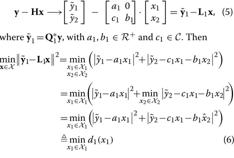
Other ‘punctured’ structures are also possible for a 4×4 system as illustrated in Figure 2. They differ in 1) the num-ber of layers over which symbols are enumerated ( enumer-ation set), 2) the submatrix structure used to propagate these enumerated symbols and cancel their interference effect from the remaining layers (interference cancellation set), and 3) the number of layers in which the minimum distance and associated symbol can be obtained by slicing after interference cancellation (slicer set). LetEdenote the size of the enumeration set,Sthe size of the slicer set, and
(a) (b) (c) (d) (e)
Figure 2(1, 3×1, 3)(a),(2, 2×2, 2)(b), and(3, 1×3, 1)(c) punctured structures.
S×Ethe size of the interference cancellation set. We refer to this structure using the triplet(E,S×E,S). For example, in Figure 2a, we enumerate overE=1 layer only, cancel interference from this layer to the three other layers using a 3×1 structure, and slice overS=3 layers. In the struc-ture in Figure 2b, we enumerate overE=2 layers, cancel interference using a 2×2 structure, and slice overS=2 layers.
LLR values are generated for bits in symbols included in the enumeration set only. Complementary structures that enumerate symbols on other layers are required to gen-erate their respective LLRs. For example, the(1, 3×1, 3) structure requires three other similar structures to gener-ate LLRs for layers 2 to 4 (see Figure 1c,d,e). The(2, 2×2, 2) structure of Figure 2b on the other hand requires only one identical structure to generate LLRs for both layers 3 and 4, while Figure 2c requires one non-identical(1, 3×1, 3) structure to handle layer 4.
4.1 Preliminaries
LetH= [h1h2 · · · hN], and assumeHhas full column rank. For simplicity, we assumeN=Min the remainder of this work. We seek a matrixW=[w1w2 · · · wN]∈CN×N that transformsHinto apuncturedLTML=[lij]∈CN×N withlii∈R+, such that:
W∗H=L. (12)
The aim is to induce a specific pattern of zeros below the main diagonal ofLby appropriately choosing the columns of W. Setting W = (H∗H)−1H∗ to be the left Moore-Penrose pseudo-inverse ofHwould obviously zero-out all entries inLbelow the main diagonal, resulting inL=IN. On the other hand, choosing W to be an orthonormal basis of the column space ofH, would transformHinto a regular (i.e., unpunctured) LTM, withWbeing unitary.
In general, if Lis punctured, then W is non-unitary. However, we impose the condition on the column vectors ofWto have unit length, i.e.,w∗nwn=1 forn=1,· · ·,N, or
diagW∗W=[ 1 1 · · · 1]T1×N. (13)
This guarantees that, whenyis left-multiplied byW∗, the transformed noise vector W∗n has an unaltered covariance matrix E[W∗nn∗W] = σn2IN. Note also that non-zero off-diagonal entries of the Gram matrixW∗W
correspond to pairs of column vectors in W that are non-orthogonal.
4.2 Proposed WL decomposition scheme
LetP=H(H∗H)−1H∗be the orthogonal projection onto the column space ofH, andP⊥=I−H(H∗H)−1H∗be the orthogonal projection onto the left nullspace ofH. LetHI
be the submatrix formed by the columns ofHwhose index nbelongs to setI. For example, ifH=[h1h2h3h4] and
I={1, 2}, thenHI=[h1h2].
LetInbe column index set of the entries in thenth row ofHto be zeroed out. Define thenth column vectorwn= P⊥Inhn, where
P⊥In =IN−HIn
H∗InHIn−1H∗In (14)
andHIn={hm|m∈In}. To satisfy (13), first note that
w∗nwn=h∗n
P⊥In
∗
P⊥Inhn=h∗nPI⊥nhn=w∗nhn,
where the second equality follows sinceP⊥Inis a projection
matrix, and henceP⊥In
∗
=P⊥InandP⊥InP⊥In=P⊥In. Hence the normalized vectorwn, defined as
wn=
wn
wn ,
withwn=
h∗nP⊥Inhn, has unit length. We have the following main result:
Theorem 1(WL decomposition).LetIn,n=1,· · ·,N, be the column index sets where puncturing is desired in each row n ofH. Form the submatricesHInand their pro-jection matrices P⊥In as noted above. Let D =[dn]∈ R+ be a diagonal matrix whose entries are given by dn =
1
W∗=D
when right multiplied byH, zeros out the entries in the rows ofHat column positions given inIn, for all n, and satisfies condition (13). nulls thenth row ofHonly at the column indices given in In.
Example 1.For a4×4MIMO system, choosing the punc-turing sets asI1 = {2, 3, 4},I2= {3, 4},I3= {2, 4},I4= results in the form of Figure 2b, while the choice I1 = {2, 3, 4},I2= {1, 3, 4},I3= {1, 2, 4},I4= {∅}results in the form of Figure 2c.
TheW,Lpair in (12) that puncturesHinto a given lower triangular structure is not unique sinceWis non-unitary. But any other pair that generates the same structure is related to W,Lby a matrix transformation as the next lemma shows.
Lemma 1 (Similar WL decompositions).Let W1,W2
be two distinct matrices that transform Hinto two dis-tinct but identically punctured LTMsL1andL2. Then the orthonormal bases of the column space ofW1andW2are both identical to that ofH, and
L1=R∗1R∗2−1L2, W1=R1R−21W2 (16)
5 Reduced-complexity WL decomposition using QLD
A brute force approach for computingWinvolves exten-sive matrix inversion, which is computationally expenexten-sive and prone to numerical error when executed on DSP or dedicated hardware with finite precision. We develop next an efficient scheme to determineW using the modified Gram-Schmidt orthogonalization procedure [49-51] fol-lowed by elementary matrix operations. From Lemma 1, any otherWthat produces an identical structure is related by (16).
Assume that H is decomposed into a unitary matrix
Q1=[q1q2 · · · qN] and a lower triangular matrixL1= [lij]N×Nwith real and positive diagonal elements. We then haveQ∗1H = L1. Obviously,q1∗q1=1 andq∗1hm=0 for
puncture the required entry and update the columns of
Q1accordingly. These operations are repeated for all other column entriesm<nto be punctured in rown. Finally,qn is normalized to have unit length, and the non-zero entries in rownofL1are updated:
The operations in (17)-(18) followed by the normal-ization steps (19)-(20) are repeated for all rowsnwhere puncturing is required. The resultingQ1isW, andL1is the desired punctured LTML.
In matrix form, we can write (17)-(18) using elementary matricesEm=[enj], 1≤m≤N, which differ fromIN by a single elementary row operation, and defined as follows:
enj=
The product of these elementary matrices forms the unscaled matrices L2 = (En· · ·E1)L1 and Q∗2 =
The scaling operations (19)-(20) can be written using the diagonal matrix D = [dn] ∈ R+, where dn = 1Q∗2Q2nn and [·]nn denotes thenth diagonal ele-ment. The desired (scaled) matrices are given byW∗ = DQ∗2andL=DL2.
For detection, the product W∗y must be formed as well. This can simply be handled by first left-augmenting
y to H, and then performing QLD on the augmented matrix to form QL = y|H. When carrying out the orthogonalization procedure, the same operations applied to the columns of H are applied to the aug-mented column. This results in Q = [0N×1|Q] and L = y|L, where QL = H and y = Q∗y, with y
essentially generated as a by-product of the decomposi-tion. Next, when carrying out operations (17)-(18) fol-lowed (19)-(20) to puncture a given entry, these operations are also applied on the leftmost column of L which containsy.
Algorithm 1 summarizes the steps of the proposed WLD scheme. Step 1 performs augmented QLD, while Step 2 performs nulling and normalization.
5.1 Complexity
We next analyze the complexity in terms of floating-point operations (flops) based on real multiplication (RMUL)
Algorithm 1:Optimized WL decomposition algorithm
L=WLD(H,y,I)
Input: ChannelH,y, and puncturing setsI={I2,· · ·,IN} Output: TransformedL=W∗y|W∗H
# Note: col indices below account for augmented col inQand
L
# Step 1: perform augmented QL decomposition
Q←y|H,L←0N×(N+1)
forn=N+1 :−1 : 2do # loop over cols ofH L(n−1,n)← qn
qn←qn/L(n−1,n)
form=n−1 :−1 : 1do # loop over cols left ofhn L(n−1,m)←q∗nqm
qm←qm−L(n−1,m)qn end
end
# Step 2: puncture using elementary row operations
forn=2 :Ndo # loop over rows ofLthat need puncturing
form=1 :n−1,m∈Indo # loop over cols to be
punctured
α←L(n,m+1)/L(m,m+1)
qn+1←qn+1−α∗qm+1
L(n, 1 :m+1)←L(n, 1 :m+1)−αL(m, 1 :m+1)
end
L(n, 1 :n+1)←L(n, 1 :n+1)/qn+1
qn+1←qn+1/qn+1# included only for completeness
end
and addition (RADD). We assume that real division and square-root operations are equivalent to a RMUL. Also, complex multiplication requires 4 RMUL and 2 RADD, while complex addition requires2 RADDoperations. Aug-mented QLD requires
θ1=(4N3−N2−N)RADD+(4N3+3N2)RMUL (22)
flops, while puncturing requires
θ2=2 3(8N
3−15N2+4N−12)RADD
16 3N
3−7N2+8 3N−20
RMUL
(23)
flops, assuming a(1,(N−1)×1,N−1)structure. In com-parison, [48] requires (16N4−4N3)RMUL and(16N4− 4N3)RADD.
6 Optimized detection algorithm
We next present a detection algorithm based on the pro-posed WLD scheme. We decomposeHintoTpunctured LTMs havingidenticalstructure(E,S×E,S) whereT = N/Eas follows. TheNstreams are decoupledEat a time inTsteps by cyclically shifting the columns ofHusing the permutation
πt(i)=mod(i+(t−1)E−1,N)+1, i=1,· · ·,N, (24)
for t = 1,· · ·,T. Each permuted H is then WL-decomposed into W(t),L(t), wherein the E leftmost columns of L(t) correspond to E distinct decoupled streams. For example, to decouple all four streams of a 4×4 MIMO system using the (2, 2×2, 2) structure of Figure 2b,T =2 such decompositions are required, one on [h1 h2h3 h4] to decouple streams 1 and 2 and one on [h3h4h1 h2] to decouple streams 3 and 4. To allow decoupled subsets to overlap, the permutation is altered to place a stream with low reliability in several detec-tion sets. For example, to decompose the four streams in the previous example into overlapping (2, 2×2, 2) structures, four decompositions are needed based on [h1 h2 h3 h4], [h2 h3 h4 h1], [h3 h4 h1 h2], and [h4h3h2h1]. For simplicity, we assume identical constel-lationsXn=Oon all layers.
One simple approach to low-complexity MIMO detec-tion is zero-forcing. Left-multiplying y by W(t)∗ to get W(t)∗y = y(t) = L(t)x + W(t)∗n results in E decoupled streams corresponding to columns
h1,· · ·,hE. These streams can be detected separately by slicing the layers individually to find their closest symbols.
Figure 3Block diagram of the proposed WL detection algorithm.
populating the Euclidean distance of the resulting symbol vectors along the way. First partitiony(t),L(t), andxas
y(t)=
! y(1t)
y(2t)
"
, L(t)=
A(t) 0 B(t) C(t)
, x=
x1
x2
,
(25)
wherey(1t)∈CE×1,y(2t)∈CS×1,A(t)∈RE×E,B(t)∈RS×E,
C(t)∈RS×S,x1∈OE, andx2∈OS. Then the symbol vector with minimum distance for the partitioned structuretis given by
xWLt arg min x∈X
y(t)−L(t)x2
=arg min x1∈OE
y(1t)−A(t)x1 2
+y(2t)−B(t)x1−C(t)#x2 2
(26)
#x2= $
y(2t)−B(t)x1
/C(t)
%
OS (27)
Note that the first argument of the slicing operator in (27) is a vector of lengthSsinceC(t)is a diagonal matrix. Here slicing is applied to the individual elements of the vector over the constellationO. The symbols in the vector xWLt are rearranged back to their normal order using (24),
and the permuted vector is denoted asxWLt :
xWLt =πt−1xWLt .
The minimum distance dWLt itself is computed as the Euclidean distance ofyfromHxWLt (rather than the dis-tance ofy(t)fromL(t)xWLt ):
dtWL=y−H(t)xWLt 2=y(t)−L(t)xWLt 2. (28)
To compute the LLRs, we expand distances similar to (26) when taking arg min to determine the symbol vector
uWLn,k,t=arg min
The LLR values are then computed as
WL
n,k,t=y−HuWLn,k,t
2
−y−HvWLn,k,t2, (31)
forn=1,· · ·,N,k=1· · ·, log2|O|, andt=1,· · ·,T. Finally, one simple way to approximate the ML distance and LLRs is by selecting the minimum over allt in (28) and (31), respectively:
Tighter LLRs can be produced by tracking global min-imum distances rather than just minimizing over the per stream LLRs. Specifically, when using (26)-(27) for every stream t, t = 1,· · ·,T, instead of just retaining the minimum distance and its corresponding arg min symbol vector, a list of allOEdistances and their corresponding symbol vectors is populated. TheseT lists are then used to compute the LLR values by selecting the minimum dis-tances for symbol vectors from these lists having 0 or 1 in the desired bit position where the LLR value is to be computed.
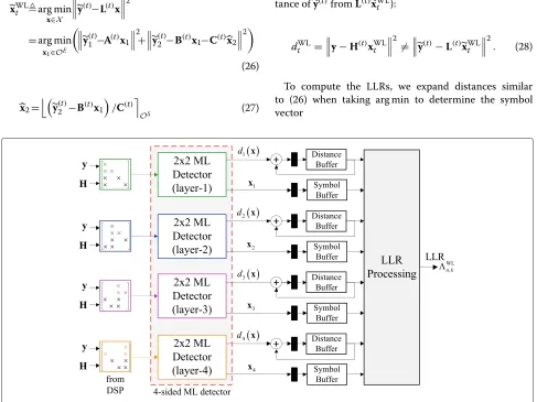
The pseudo-code in Algorithm 2 summarizes the steps of the proposed WLD detection algorithm. It produces tight LLRs according to the previous discussion, using the equations marked with (). Figure 3 shows a block dia-gram describing the dataflow of the algorithm. ForN=2 layers, the algorithm is optimal and reduces to that in [45] since theWs are unitary in this case. WhenE=1 and dis-tances in (28) are computed based onLinstead ofH, the algorithm reduces to that in [48].
Algorithm 2:Optimized detection algorithm
=WDetector(H,y)
Input: Channel matrixH∈CN×N; received vector
y∈CN×1
Output: LLR values∈Rq×1
Data:Tpunctured matricesLof structure (E,S×E,S); puncturing setI; distance
Depending on the target throughput and the number of antennasNin the MIMO systems, multiple 2×2 detector cores can be configured to construct anN-stream MIMO detector. Figure 4 shows a four-sided fully parallel 4×4 MIMO detector that uses four cores to process the four streams. Here distance buffering and accumulation are needed before LLR processing in order to adjust the indi-vidual LLRs according to earlier discussion. It is assumed that an external digital signal processor (DSP) must supply the WLD matrix inputs for all four streams according to the decompositions in (25). If chip area is the constraining factor, a MIMO detector can be built using a single core that is time-multiplexed among the four streams.
7 Performance simulation results
simulations of a MIMO system employing four transmit and four receive antennas. The channel encoder is based on the LTE turbo encoder specification [52] with inter-leaver length 1,024, using 16-QAM and 64-QAM mod-ulation constellations. The channel entries are assumed to be independent and identically distributed (i.i.d.) com-plex Gaussian random variables. At the receiver end, we assume perfect channel knowledge. The turbo decoder implements the trueA Posteriori Probability algorithm, and performs four (full) decoding iterations.
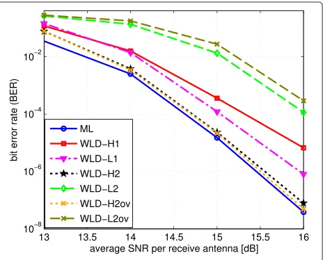
Figure 5 compares the BER versus SNR per receive antenna of the proposed WLD scheme with E = 1 and 2 structures, versus ML, ZF, the approach of [48], and the sphere decoder with radius clipping [30], for 16-QAM. Both overlapping and non-overlapping subsets are considered. Furthermore, two scenarios for distance com-putations in (28) are followed; one based onHand one onL. The curve labeledWLD-H1corresponds to the pro-posed WLD detection scheme withE = 1 and distance computations based onHin (28), while the curve labeled
WLD-L1corresponds to the proposed scheme withE=1 but with distance computations based onLin (28). Simi-larly for the curves labeledWLD-H2andWLD-L2, but with E = 2 and non-overlapping decomposition sets. Finally the curve labeledWLD-H2ovcorresponds toE = 2 but with four overlapping(2, 2×2, 2)structures.
As shown in the figure, the plots demonstrate that the proposed WLD algorithm with E = 2 using H dis-tances with overlapping subsets performs virtually as ML and is less than 0.1 dB away from ML with no overlap-ping subsets. Furthermore, theWLD-L2scheme performs much worse thanWLD-H2. For decompositions with sin-gle streams,Ldistances perform better thanHdistances; theWLD-H1scheme exhibits an error floor. Compared to
Figure 5BER vs. SNR plots for 16-QAM constellation.
the well-known sphere decoding algorithm with radius-clipping [30], the proposed WLD-based schemes achieve better performance especially withE=2 structures.
Figure 6 compares the BER performance of the WLD schemes using 64-QAM constellations. The plots demon-strate again that the WLD scheme withE = 2 usingH
distances and overlapping subsets performs very close to ML. It is worth mentioning thatWLD-H2again performs very close toWLD-H2ov(and hence to ML), which has sig-nificant hardware saving implications. Note here that the
WLD-L2ovscheme usingL-distances withE =2 overlap-ping decompositions performs the worst among the WLD schemes.
Finally, another important advantage of the proposed schemes is the significant reduction in simulation time observed when generating the BER plots. On a typical multi-core server machine, one simulation point takes in the order of few hours to complete, while the sphere decoder and ML approaches require few days. This is very valuable for designers when doing rapid evaluations and tradeoff analyses of various MIMO system features.
8 Conclusions
A low-complexity MIMO subspace detection algorithm has been presented. By decomposing the channel matrix of anM-stream MIMO system into a generalized elemen-tary matrix structure, the detection problem becomes a generalization of that of a two-stream detection problem, which admits a simple architecture suitable for high-speed implementation. Multiple two-stream detector cores can be employed in parallel to improve detection throughput. The channel decomposition scheme is cast in terms of the standard Gram-Schmidt QL decomposition, which is supported in most modern DSPs.
Competing interests
The author declares that he has no competing interests.
Received: 24 October 2014 Accepted: 9 February 2015
References
1. A Paulraj, R Nabar, D Gore,Introduction to Space-Time Wireless Communications. (Cambridge Univ. Press, Cambridge, U.K, 2003) 2. E Viterbo, J Boutros, A universal lattice code decoder for fading channels.
IEEE Trans. Inf. Theory.45(5), 1639–1642 (1999)
3. O Damen, A Chkeif, J-C Belfiore, Lattice code decoder for space-time codes. IEEE Commun. Lett.4(5), 161–163 (2000)
4. E Agrell, T Eriksson, A Vardy, K Zeger, Closest point search in lattices. IEEE Trans. Inf. Theory.48(8), 2201–2214 (2002)
5. GJ Foschini, Layered space-time architecture for wireless communication in a fading environment when using multi-element antennas. Bell Labs Tech. J.1(2), 41–59 (1996)
6. Y Jiang, J Li, WW Hager, Joint transceiver design for MIMO communications using geometric mean decomposition. IEEE Trans. Signal Process.53(10), 3791–3803 (2005)
7. Y Jiang, J Li, WW Hager, Uniform channel decomposition for MIMO communications. IEEE Trans. Signal Process.53(11), 4283–4294 (2005) 8. SL Ariyavisitakul, J Zheng, E Ojard, J Kim, Subspace beamforming for
near-capacity MIMO performance. IEEE Trans. Signal Process.56(11), 5729–5733 (2008)
9. Y Chen, ST Brink, inProc. IEEE Int. Symp. Personal Indoor and Mobile Radio Commun. (PIMRC). Near-capacity MIMO subspace detection (Toronto, Canada, 2011), pp. 1733–1737
10. E Biglieri, R Calderbank, A Constantinides, A Goldsmith, A Paulraj, HV Poor, MIMO Wireless Communications. (Cambridge Univ. Press, Cambridge, U.K, 2007)
11. B Hassibi, inProc. IEEE Int. Conf. Acoustics, Speech, and Signal, Process. (ICASSP). An efficient square-root algorithm for BLAST (Istanbul, Turkey, 2000), pp. 5–9
12. GD Golden, JG Foschini, RA Valenzuela, PW Wolniansky, Detection algorithm and initial laboratory results using V-BLAST space-time communication architecture. IEE Electron. Lett.35(1), 14–15 (1999) 13. D Wübben, R Böhnke, V Kühn, K Kammeyer, inProc. IEEE Vehicular Technol.
Conf. (VTC). MMSE extension of V-BLAST based on sorted QR decomposition (Orlando, Florida, 2003), pp. 508–512
14. C Studer, S Fateh, D Seethaler, ASIC implementation of soft-input soft-output MIMO detection using MMSE parallel interference cancellation. IEEE Trans. Syst. Sci. Cybern.47(7), 1754–1765 (2011) 15. E Viterbo, E Biglieri, in14ème Colloque GRETSI. A universal decoding
algorithm for lattice codes (Juan-Les-Pins, France, 1993), pp. 611–614 16. B Hochwald, S ten Brink, Achieving near-capacity on a multiple-antenna
channel. IEEE Trans. Commun.51(3), 389–399 (2003) 17. B Hassibi, H Vikalo, On sphere decoding algorithm. I. Expected
complexity. IEEE Trans. Signal Process.53(8), 2806–2818 (2005) 18. J Jaldén, B Ottersten, On the complexity of sphere decoding in digital
communications. IEEE Trans. Signal Process.53(4), 1474–1484 (2005) 19. D Seethaler, J Jaldén, C Studer, H Bölcskei, On the complexity distribution
of sphere decoding. IEEE Trans. Inf. Theory.57(9), 5754–5768 (2011) 20. K-W Wong, C-Y Tsui, RS-K Cheng, W-H Mow, inProc. IEEE Int. Symp. on
Circuits and Systems (ISCAS). A VLSI architecture of aK-best lattice decoding algorithm for MIMO channels, vol. 3 (Scottsdale, Arizona, 2002), pp. 273–276
21. M Wenk, M Zellweger, A Burg, N Felber, W Fichtner, inProc. IEEE Int. Symp. on Circuits and Systems (ISCAS). K-best MIMO detection VLSI architectures achieving up to 424Mbps (Island of Kos, Greece, 2006), pp. 1151–1154 22. S Mondal, A Eltawil, C-A Shen, K Salama, Design and implementation of a
sort freeK-best sphere decoder. IEEE Trans. VLSI Syst.18(10), 1497–1501 (2010)
23. L Liu, F Ye, X Ma, T Zhang, J Ren, A 1.1-Gb/s 115-pJ/bit configurable MIMO detector using 0.13μm CMOS technology. IEEE Trans. Circuits Syst. II. 57(9), 701–705 (2010)
24. C-A Shen, A Eltawil, K Salama, Evaluation framework forK-best sphere decoders. J. Circuits Syst. Comput.19(5), 975–995 (2010)
25. M Shabany, P Gulak, A 675 Mbps,4×464-QAM K-Best MIMO detector in 0.13μm CMOS. IEEE Trans. VLSI Syst.20(1), 135–147 (2012)
26. M Mahdavi, M Shabany, Novel MIMO detection algorithm for high-order constellations in the complex domain. IEEE Trans. VLSI Syst.21(5), 834–847 (2013)
27. D Garrett, L Davis, S ten Brink, B Hochwald, G Knagge, Silicon complexity for maximum likelihood MIMO detection using spherical decoding. IEEE J. Solid-State Circuits.39(9), 1544–1552 (2004)
28. Z Guo, P Nilsson, inProc. IEEE CAS Symp. Emerging Technologies. A VLSI architecture of the Schnorr-Euchner decoder for MIMO systems, vol. 1 (Shanghai, China, 2004), pp. 65–68
29. A Burg, M Borgmann, M Wenk, M Zellweger, W Fichtner, H Bölcskei, VLSI implementation of MIMO detection using the sphere decoding algorithm. IEEE J. Solid-State Circuits.40(7), 1566–1577 (2005)
30. C Studer, A Burg, H Bölcskei, Soft-output sphere decoder: algorithms and VLSI implementation. IEEE J. Sel. Areas Commun.26(2), 290–300 (2008) 31. C-H Yang, D Markovic, A flexible DSP architecture for MIMO sphere
decoding. IEEE Trans. Circuits Syst. I.56(10), 2301–2314 (2009) 32. C-H Yang, D Markovic, inEuropean Solid-State Circuits Conf. (ESSCIRC). A
2.89 mW 50 GOPS16×1616-core MIMO sphere decoder in 90 nm CMOS (Athens, Greece, 2009), pp. 344–347
33. F Borlenghi, EM Witte, G Ascheid, H Meyr, A Burg, inIEEE Asian Solid State Circutis Conf. (A-SSCC). A 772 Mbit/s 8.81 bit/nJ 90 nm CMOS soft-input soft-output sphere decoder (Jeju, Korea, 2011), pp. 297–300 34. L Liu, J Lofgren, P Nilsson, Area-efficient configurable high-throughput
signal detector supporting multiple MIMO modes. IEEE Trans. Circuits Syst. I.59(9), 2085–2096 (2012)
35. Y Sun, JR Cavallaro, Trellis-search based soft-input soft-output MIMO detector: algorithm and VLSI architecture. IEEE Trans. Signal Process. 60(5), 2617–2627 (2012)
36. X Chen, G He, J Ma, VLSI implementation of a high-throughput iterative fixed-complexity sphere decoder. IEEE Trans. Circuits Syst. II.60(5), 272–276 (2013)
37. MM Mansour, S Alex, MA Jalloul, Reduced complexity soft-output MIMO sphere detectors – Part I Algorithmic optimizations. IEEE Trans. Signal Process.62(21), 5505–5520 (2014)
38. MM Mansour, S Alex, MA Jalloul, Reduced complexity soft-output MIMO sphere detectors – Part II Architecutral optimizations. IEEE Trans. Signal Process.62(21), 5521–5535 (2014)
39. M-Y Huang, P-Y Tsai, Toward multi-gigabit wireless: design of high-throughput MIMO detectors with hardware-efficient architecture. IEEE Trans. Circuits Syst. I.61(2), 613–624 (2014)
40. J Choi, A Singer, J Lee, N-I Cho, Improved linear soft-input soft-output detection via soft feedback successive interference cancellation. IEEE Trans. Commun.58(3), 986–996 (2010)
41. RC de Lamare, R Sampaio-Neto, Adaptive reduced-rank equalization algorithms based on alternating optimization design techniques for MIMO systems. IEEE Trans. Veh. Technol.60(6), 2482–2494 (2011) 42. T Hwang, Y Kim, H Park, Energy spreading transform approach to achieve
full diversity and full rate for MIMO systems. IEEE Trans. Signal Process. 60(12), 6547–6560 (2012)
43. D Persson, J Kron, M Skoglund, EG Larsson, Joint source-channel coding for the MIMO broadcast channel. IEEE Trans. Signal Process.60(4), 2085–2090 (2012)
44. RC de Lamare, Adaptive and iterative multi-branch MMSE decision feedback detection algorithms for multi-antenna systems. IEEE Trans. Wireless Commun.12(10), 5294–5308 (2013)
45. M Siti, MP Fitz, inProc. IEEE Int. Conf. Commun. (ICC). A novel soft-output layered orthogonal lattice detector for multiple antenna
communications, vol. 4 (Istanbul, Turkey, 2006), pp. 1686–1691 46. M Siti, MP Fitz, inProc. IEEE Wireless Commun. and Netw. Conf. (WCNC). On
layer ordering techniques for near-optimal MIMO detectors (Hong Kong, 2007), pp. 1199–1204
47. MS Yee, inProc. IEEE Int. Conf. Acoustics, Speech, and Signal, Process. (ICASSP). Max-log-MAP sphere decoder, vol. 3 (Philadelphia, PA, 2005), pp. 1013–1016
49. GH Golub, CFV Loan,Matrix Computations, 3rd edn. (Johns Hopkins Univ. Press, Baltimore, MD, 1996)
50. RC-H Chang, C-H Lin, K-H Lin, C-L Huang, F-C Chen, Iterative QR decomposition architecture using the modified Gram-Schmidt algorithm for MIMO systems. IEEE Trans. Circuits Syst. I.57(5), 1095–1102 (2010) 51. D Wübben, R Böhnke, J Rinas, V Kühn, K Kammeyer, Efficient algorithm for
decoding layered space-time codes. IEE Electron. Lett.37(22), 1348–1350 (2001)
52. Evolved Universal Terrestrial Radio Access (E-UTRA); Physical Channels and Modulation. TS 36.211 3GPP. http://www.3gpp.org
Submit your manuscript to a
journal and benefi t from:
7Convenient online submission
7Rigorous peer review
7Immediate publication on acceptance
7Open access: articles freely available online
7High visibility within the fi eld
7Retaining the copyright to your article
![Figure 2b, T = 2 such decompositions are required, oneon [ h1 h2 h3 h4] to decouple streams 1 and 2 and oneon [ h3 h4 h1 h2] to decouple streams 3 and 4](https://thumb-us.123doks.com/thumbv2/123dok_us/950683.1116149/6.595.56.290.422.731/figure-decompositions-required-oneon-decouple-streams-decouple-streams.webp)