University of South Carolina
Scholar Commons
Theses and Dissertations
1-1-2013
Predicting the Crack Response for a Pipe with a
Complex Crack
Robert George Lukess University of South Carolina
Follow this and additional works at:https://scholarcommons.sc.edu/etd Part of theNuclear Engineering Commons
This Open Access Dissertation is brought to you by Scholar Commons. It has been accepted for inclusion in Theses and Dissertations by an authorized administrator of Scholar Commons. For more information, please [email protected].
Recommended Citation
PREDICTING THE CRACK RESPONSE FOR A PIPE WITH A COMPLEX CRACK
By
Robert G. Lukes
Bachelor of Science
University of Wisconsin – Madison, 2003
Master of Engineering Johns Hopkins University, 2006
_______________________________________________
Submitted in Partial Fulfillment of the Requirements
For the Degree of Doctor of Philosophy in
Nuclear Engineering
College of Engineering and Computing
University of South Carolina
2013
Accepted by:
Travis W. Knight, Major Professor
Sarah Baxter, Committee Member
Michael Sutton, Committee Member
Elwyn Roberts, Committee Member
David Rudland, Committee Member
ii
iii DEDICATION
This work is dedicated to my family and all the people who assisted in the
iv
ACKNOWLEDGMENT
I would like to acknowledge the tremendous support provided by the NRC in the
completion of this research. I would also like personally thank NRC staff members Dr.
Dave Rudland, Dr. Aladar Csontos, Jim Beardsley, Joelle Starefos, John Lubinski, Dr.
David Esh, Dr. Timothy McCartin, and Christopher Hunter. All of whom contributed
directly to the completion of my educational goals at one point in time.
Thanks to Battelle for providing a significant amount of information used as the
basis for this research. In addition, I would like to thank the Battelle staff for providing
me support when analyzing the data and performing the analysis. This project would not
have been possible without their support.
I would also like to thank Dr. Knight and the rest of the engineering faculty at
University of South Carolina for the time and effort they spend educating the next
generation of engineers and researchers. During my time at the university I was
continually amazed by the intelligence and creativity of the faculty.
Finally I would like thank my family for their support and motivation. Their
tireless work maintaining our household allowed me the freedom to pursue my personal
education goals. Thank you Kim, Reagan, Zoe, Agi, Tammie, and Mom for everything
v ABSTRACT
Traditional flaw evaluation in the nuclear field uses conservative methods to
predict maximum load carrying capacity for flaws in a given pipe. There is a need in the
nuclear industry for more accurate estimates of the load carrying capacity of nuclear
piping such that probabilistic tools can be used to predict the time to failure for various
types of cracks. These more accurate estimates will allow the nuclear industry to repair
flaws at a more appropriate time considering external factors such as costs and man-rem
planning along with the flaw repair. Analysis of the maximum load carrying capacity of
a pipe with a complex crack (CC) has gained increased importance due to the recent
identification of long CC’s that have appeared in dissimilar metal (DM) welds thought to
be caused by primary water stress corrosion cracking (PWSCC).
A numerical solution for a single material with a weld was developed that gives
an accurate maximum load and crack driving force prediction for a pipe with a through
wall crack (TWC), called LBBEng. To support the analysis of a CC, traditionally, an
assumption is used that the CC performs similar to that of a TWC of a reduced thickness
(TWCr). This modification gives a conservative prediction of the maximum load
carrying capacity for a CC in a single material but was never verified for a CC in a DM
weld. The research performed in this work demonstrates that the crack response of a CC
can be predicted by a TWC model when modifications are made to the reduced thickness
vi
TABLE OF CONTENTS
DEDICATION ... iii
ACKNOWLEDGEMENT ... iv
ABSTRACT ... v
LIST OF TABLES ... viii
LIST OF FIGURES ... ix
LIST OF SYMBOLS ... xiii
LIST OF ABBREVIATIONS ... xv
1. INTRODUCTION ... 1
1.1 HISTORY OF DISSIMILAR METAL WELD CRACKING ... 1
1.2 LBB AND PWSCC ... 6
1.3 STATEMENT OF THE PROBLEM ... 7
1.4 RESEARCH HYPOTHESIS ... 8
1.5 SIGNIFICANCE OF RESEARCH ... 9
2. REVIEW OF LITERATURE ... 10
2.1 INTRODUCTION ... 10
2.2 FRACTURE IN NUCLEAR PIPING ... 10
2.3 PAST RESEARCH IN NUCLEAR PIPING FRACTURE MECHANICS ... 13
2.4 J-ESTIMATION SCHEMES ... 27
vii
3.1 METHODOLOGY ... 35
3.2 DESIGN OF EXPERIMENT ... 35
3.3 TEST PLAN ... 45
3.4 CURRENT SOLUTIONS TO COMPLEX CRACKS ... 48
3.5 DEVELOPMENT OF A NEW REDUCED THICKNESS METHOD ... 51
4. RESULTS ... 57
4.1 EXPERIMENT ANALYSIS ... 57
4.2 GENERAL MODEL PARAMETERS ... 59
4.3 COMPLEX CRACK RESPONSE PREDICTION ... 66
5. DISCUSSION OF RESULTS ... 77
6. FUTURE RESEARCH ... 85
7. CONCLUSIONS ... 87
REFERENCES ... 88
APPENDIX A-EXPERIMENT DATA ... 92
APPENDIX B-MATERIAL PROPERTIES ... 96
APPENDIX C-DETAILED JVERSUS MOMENT PLOTS ... 99
viii LIST OF TABLES
Table 3.1. Material properties for carbon and stainless steel ...42
Table 3.2. Test matrix of dissimilar metal weld pipe experiments ...46
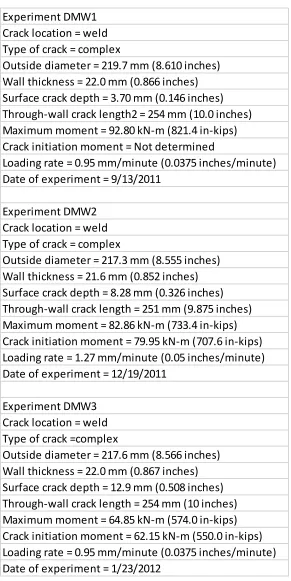
Table 4.1. Applicable data from the DMW 1, 2, and 3 experiments ...64
Table 4.2. 4 point bend model dimensions. ...65
Table A.1. DMW1 CC - SC 16.9% 37% TWC ...93
Table A.2. DMW 2 CC- SC 38.3% 37% TWC ...94
Table A.3. DMW3 CC – SC 58.6%, 37% TWC...95
Table B.1. Carbon Steel ...96
Table B.2. Inconel 182/82 ...97
ix
LIST OF FIGURES
Figure 1.1. Illustrated example of a DM weld showing the different material regions ...1
Figure 1.2. Typical welds for a VHP ...2
Figure 2.1. Test matrix from full scale pipe fracture experiments showing the number of experiments by diameter and crack geometry ...14
Figure 2.2. Test matrix from the full scale pipe fracture experiments showing the number of experiments by diameter and loading type ...15
Figure 2.3. Test matrix from the full scale pipe fracture experiments showing the number of experiments by diameter and material type. ...15
Figure 2.4. Ratio of J from CC experiments to J of the TWC experiments as a function of d/t ...17
Figure 2.5. Weld metal and fusion line J-R curve data ...21
Figure 2.6. Comparison of leak rates for PICEP and SQUIRT for the Wolf Creek Flaw...26
Figure 2.7. Surface crack idealized shapes ...32
Figure 2.8. Complex crack shape from Duane Arnold nuclear plant ...32
Figure 2.9. Crack shape modification for current estimation schemes ...33
Figure 3.1. Test specimen with arrows annotating the unload marks ...36
Figure 3.2. 500 kip MTS servo-hydraulically controlled test frame in Battelle’s Fatigue and Structures Laboratory ...37
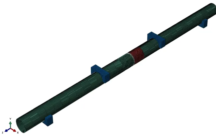
Figure 3.3. Strongback and saddle design to be used in DMW pipe fracture experiments ...37
x
Figure 3.5. Video still from DMW 4 pipe test ...40
Figure 3.6. Picture of clip gage used for the CMOD measurements ...40
Figure 3.7. Blades used in machining the internal surface crack ...43
Figure 3.8. EDM cutter being used to create a simulated crack in the pipe ...44
Figure 3.9. Picture of electrode used in EDM process with electrode design feature used to reduce taper circled ...44
Figure 3.10. Image recorded from DMW 4 experiment illustrating crack growth and the crack tip. ...47
Figure 3.11. Estimation scheme selections in NRCPipe software package ...49
Figure 3.12. Illustration of complex crack treating using LBB.ENG2 and other estimation solutions. The images are complex crack, TWC, and the theoretical TWC with reduced thickness respectively ...50
Figure 3.13. Image of DMW1 illustrating crack growth direction ...51
Figure 3.14. Illustration showing the conservative behavior of the reduced thickness assumption ...52
Figure 3.15. Illustration showing the conservative behavior of the reduced thickness assumption ...53
Figure 3.16. Illustration showing the conservative behavior of the reduced thickness assumption ...54
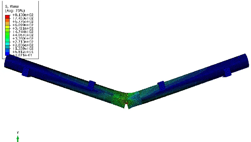
Figure 3.17. 4-point bend model illustration prior to modeling ...55
Figure 3.18. 4-point bend model after load application ...55
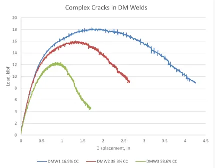
Figure 4.1. Plot of raw data from the DMW1, 2, and 3 CC experiments. ...58
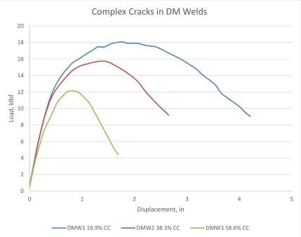
Figure 4.2. Plot of reduced data from DMW 1, 2, and 3 CC experiments. ...59
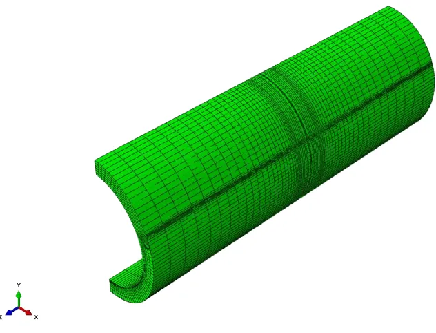
Figure 4.3. Isometric view of CC and TWC model mesh used for the analysis. ...60
xi
Figure 4.5. Illustration of the 4 point bend model created to verify the new model
technique ...63
Figure 4.6. 4 point bend model validation. ...66
Figure 4.7. Results recorded from the DMW 1 experiment. ...67
Figure 4.8. Results recorded from the DMW 2 experiment. ...68
Figure 4.9. Results recorded from the DMW 3 experiment. ...69
Figure 4.10. Illustration of the DMW1 FE models. Comparing the driving force for crack growth of the RT, FT, and MRT models to the CC FE model. ...70
Figure 4.11. Illustration of the DMW2 FE models. Comparing the driving force for crack growth of the RT, FT, and MRT models to the CC FE model. ...72
Figure 4.12. Illustration of the DMW3 FE models. Comparing the driving force for crack growth of the RT, FT, and MRT models to the CC FE model. ...73
Figure 4.13. Illustration of the FE models using the MRT and RT as compared to the test data. ...74
Figure 4.14. Illustration of the FE models using the MRT and RT as compared to the test data. ...75
Figure 4.15. Illustration of the FE model using the MRT and RT as compared to the test data. ...76
Figure 5.1. Isometric view of DMW 2 5c CC model, moment applied ...79
Figure 5.2. Side view (YZ) of DMW 2 5c CC model, moment applied ...79
Figure 5.3. Side view (YZ) of DMW 2 5c modified TWCr model moment applied ...80
Figure 5.4. Illustration of the DMW2 (5c) FE models. Comparing the driving force for crack growth of the RT, FT, and MRT models to the CC FE model. ...80
Figure 5.5. Graphical illustration of the correlation between the SC depth and the MRT. ...82
Figure 5.6. J versus moment curves for the new reduced thickness models ...83
xii
Figure C.1. Illustration of the DMW 2 FE models. Comparing the driving force for crack growth of all the performed TWC models to the CC FE model. ...99
Figure C.2. Illustration of the DMW 2 FE models. Comparing the driving force for crack growth of all the performed TWC models to the CC FE model. ...100
Figure C.3. Illustration of the DMW 2 (5c) FE models. Comparing the driving force for crack growth of all the performed TWC models to the CC FE model. ...101
xiii
LIST OF SYMBOLS
a Crack Length
𝛼 Ramberg-Osgood parameter
∆a Increment of Crack Growth
𝐸 Elastic modulus
εo Ramberg-Osgood reference strain
ε Engineering strain
J Measure of Elastic-Plastic Energy
JCC J of the complex crack
JTWC J of the through wall crack
Ji Elastic-Plastic Energy at Crack Initiation
Jic Fracture toughness
Je Elastic component of J
JP Plastic component of J
JR Crack growth resistance
J-R J-resistance curve
JD-R J-resistance curve based on deformation theory
JM-R J-resistance curve based on Modified J
𝐾𝐼𝑐 Plane strain fracture toughness
xiv
𝑀 Moment
𝑀𝑂 The limit moment of a through wall cracked pipe under pure bending
𝑛 Ramberg-Osgood strain hardening exponent
𝜂 − 𝑓𝑎𝑐𝑡𝑜𝑟 Method for estimating the fracture toughness of a pipe experiment from experimental moment rotation relationship
𝜎 Stress
𝜎𝑓 Flow stress
𝜎𝑂 Ramberg-Osgood reference stress
σy Yield stress
𝑅𝑚 Mean radius
𝑡 Wall thickness
xv
LIST OF ABBREVIATIONS
ABAQUS ... Finite element analysis computer software
ASME ... American Society of Mechanical Engineers
ASTM ... American Society for Testing and Materials
AXIALCK... Axial crack database
BINP ... Battelle integrity of nuclear piping program
BWR ...Boiling water reactor
CC ... Complex Crack
CGR ... Crack growth rate
CIRCUMCK ... Circumferential crack database
COD ... Crack opening displacement
CRDM ... Control rod drive mechanism
DM ... Dissimilar metal
DMW ... Dissimilar metal weld
EMC2... Engineering Mechanics Corporation of Columbus, Columbus, Ohio,
EPFM ... Elastic-plastic fracture mechanics
EPRI ... Electric Power Research Institute
FE ...Finite element
FEA ... Finite element analysis
xvi
GE ... General Electric
IPIRG ... International Piping Integrity Research Group
IPIRG 2 ... International Piping Integrity Research Group
IGSCC ... Intergranular Stress Corrosion Cracking
LBB ... Leak-before-break
LEFM ... Linear elastic fracture mechanics
MRP ... EPRI materials reliability program
MRT ... Modified reduced thickness
MRTF ... Modified reduced thickness factor
NIST ... National Institute of Standards and Technology
NRC ... Nuclear Regulatory Commission
NRCpipe ... NRC sponsored fracture computer software
NSC ... Net section collapse
PICEP ... Pipe Crack Evaluation Program
PIFRAC... NRC/Battelle pipe fracture database
PWR ... Pressurized water reactor
PWSCC ... Primary Water Stress Corrosion Cracking
PVP ... Pressure vessel piping
RT ... Reduced thickness
SAW ... Submerged arc weld
SC ... Surface crack
SMAW ... Shielded metal arc weld
xvii
TWC ... Through wall crack
TWCr ... Through wall crack of reduced thickness
VHP... Vessel head penetration
1 CHAPTER 1
INTRODUCTION
1.1HISTORY OF DISSIMILAR METAL WELD CRACKING
Primary Water Stress Corrosion Cracking (PWSCC) has been a known problem
in the nuclear industry since the early 1980s. PWSCC is known to occur in susceptible
materials that are in a challenging environment, both temperature and chemically, and are
under high residual stresses. These conditions exist in pressurized water reactors (PWR)
for welds that join ferritic and stainless steels, referred to as dissimilar metal (DM) welds,
specifically welds that use nickel-chromium-iron Alloy 600/82/182. As an example, DM
welds were used for control rod drive mechanism (CRDM) to vessel welds, pressurizer
nozzles, and reactor coolant loop piping to branch piping and other locations where
carbon steel and stainless steel are required to be joined. Figure 1.1 illustrates the typical
material order for a DM weld.
2
For currently operating nuclear power plants, DM welds in vessel head
penetrations (VHP) are of the most concern because of the potential for a VHP ejection.
This would result in a small-to-medium loss of coolant accident which could affect the
safe shutdown of the reactor. A typical weld of a VHP is illustrated in Figure 1.2.
Beginning in 1986, leaks in DM welds have been identified in VHP’s of operating
nuclear power plants. However, these leaks were not viewed as having high safety
significance because examinations concluded that the cracks were axial and had low
growth rates.
3
In 1991 DM weld cracks were also found in VHP at the French PWR, Bugey 3.
Several other examinations were performed at plants in France, Belgium, Sweden,
Switzerland, Spain, and Japan. Additional cracks in VHP’s were detected during these
inspections. In 1991, two percent of the VHP’s contained short axial cracks [1]. After
these findings were discovered, plans were developed by the Nuclear Regulatory
Commission (NRC) and Electric Power Research Institute (EPRI) to further assess the
possibility of DMW cracking in VHP’s. Safety assessments were completed by each of
the PWR owners groups in 1993. The NRC reviewed those assessments and concluded
that PWSCC cracking was not an immediate safety concern. The basis was that the
cracks were axial in direction, would result in detectable leakage before failure, and the
leakage would be detectable during normal visual examinations. In addition, the cost of
the additional exposure to personnel during examination and repair was not justified by
the currently viewed risk.
The first U.S. inspection of VHP’s occurred in 1994 at Point Beach Nuclear
Generating Station. No cracks were detected in its 49 CRDM penetrations. Later in
1994 an inspection was done at Oconee Nuclear Generating Station and revealed 20
shallow cracks in one penetration. D.C. Cook Nuclear Generating Station was also
inspected that year and was found to have three clusters of cracks in one VHP. Several
utilities developed susceptibility models in an attempt to predict crack growth in VHP’s
and use it as a basis for inspection. There was disagreement between NRC and the
industry on the validity of these models [1], however, at the time the NRC agreed with
4
During 2000, cracks were discovered in Alloy 182 welds joining low-alloy steel
reactor vessel hot leg nozzles to stainless steel pipes at Ringhals 4 (Sweden) and VC
Summer (United States). At VC Summer, a through wall crack (TWC) was found in the
Alloy 82/182 weld between the low-alloy steel reactor vessel outlet nozzle and the
stainless steel primary coolant pipe. Although cracking was primarily axially oriented, at
VC Summer a short and shallow circumferential crack also was discovered in the inside
diameter (ID) region of the Alloy 182 weld clad beneath the low-alloy steel nozzle
material. This circumferential crack arrested when it reached the low-alloy steel base
material. The VC Summer circumferential flaw contradicted one of the initial
assumptions that flaws were primarily axial, thus elevating the concern regarding DM
welds due to the presence of the circumferential flaws.
Several other PWSCC cracks were identified after 2000, as a result of increased
inspections. VHP cracking at Oconee Nuclear Station Unit 1 (ONS1) in November 2000
and Arkansas Nuclear One Unit 1 (ANO1) in February 2001 was limited to axial
cracking. Discovery of large circumferential cracking identified in two VHP’s, one of
which was a leaking complex crack, at Oconee Nuclear Station Unit 3 (ONS3) and
Oconee Nuclear Station Unit 2 (ONS2) in 2001 raised concerns about the potential safety
implications and prevalence of cracking in VHP nozzles in PWRs. Again, these
observations contradicted the assumption that the PWSCC flaws are predominantly axial
[2]. In 2002 Davis-Besse Nuclear Power Station identified a football-sized cavity in the
unit’s reactor vessel head. The cavity was next to a leaking nozzle with a TWC and was
in an area of the vessel head that had been covered with boric acid deposits. In 2003, a
5
(Japan). This leak was from an axial crack in the butt weld between the low-alloy steel
nozzle and the stainless steel relief valve line. In 2005, Calvert Cliffs Nuclear Power
Plant identified indications in a hot leg drain nozzle dissimilar metal weld. There were
two axial indications contained entirely within the weld and butter closely associated with
the ID and there also was one circumferential indication extending approximately 100° in
circumference, with one end oriented near one of the axial indications.
The most significant occurrence of DM weld cracking occurred in 2006. Several
circumferential cracks were identified by ultrasonic testing in three of the pressurizer
nozzle DM welds at the Wolf Creek nuclear power plant. The discovered cracks were
relatively long circumferential defects in Alloy 82/182 DM welds and were attributed to
PWSCC. In one case, the flaw was sized at 43% of the pipe circumference in length and
26% of the wall thickness in depth [3]. A flaw evaluation was performed assuming
idealized flaw shapes which demonstrated that these flaws could potentially cause rupture
before leakage [3].
As a result of the Wolf Creek finding, the NRC and the industry has implemented
an initiative to develop a more robust probabilistic analysis to evaluate identified DM
weld flaws. The results from this research will feed into model validation for the
NRC/EPRI ongoing cooperative effort on developing a modular-based probabilistic
fracture mechanics code for determining the probability of rupture entitled Extremely
6 1.2LBB AND PWSCC
The industry has a major financial interest in the approval of the LBB
methodology. LBB [41] allows for the removal of protective hardware, such as
pipe-whip restraints and jet impingement shield barriers, the redesign of pipe connected
components, their supports, and their internals, and other related changes in operating
plants. The governing section of the regulations related to LBB is General Design
Criterion 4 in Appendix A of Part 50 of Title 10 of the Code of Federal Regulations, Ref.
2.1. GDC-4 states that [23]:
"Structures, systems, and components important to safety shall be designed to
accommodate the effects of and to be compatible with the environmental conditions
associated with normal operation, maintenance, testing, and postulated accidents,
including loss-of-coolant accidents. These structures, systems, and components shall be
appropriately protected against dynamic effects, including the effects of missiles, pipe
whipping, and discharging fluids, that may result from equipment failures and from
events and conditions outside the nuclear power unit. However, dynamic effects
associated with postulated pipe ruptures in nuclear power units may be excluded from the
design basis when analyses reviewed and approved by the Commission demonstrate that
the probability of fluid system piping rupture is extremely low under conditions
consistent with the design basis for the piping."
Of particular interest to the subject of LBB, is the stipulation in GDC-4 that
allows the use of "analyses reviewed and approved by the Commission" to eliminate
7
load prediction are critical to the implementation of LBB. LBB is generally applicable
with the following exceptions:
LBB cannot be applied to individual welded joints or other discrete locations.
LBB is applicable only to an entire piping system.
LBB is typically not applicable to piping susceptible to intergrannular stress
corrosion cracking (IGSCC) or primary water stress corrosion cracking
(PWSCC). However, if the applicant can demonstrate to the NRC through
analysis that effective mitigation measures are in place to counteract these
mechanisms.
Thus, there is an industry need for a predictive tool that can accurately evaluate complex
cracks, such as those associated with PWSCC.
1.3STATEMENT OF THE PROBLEM
Throughout the 1980’s and 1990’s, extensive research was conducted on the
stability of flaws in nuclear piping. All of these experiments and the developed
methodologies focused on idealized flaws in similar metals welds and their base metals.
However, with the occurrence of PWSCC in DM welds, i.e., a nickel based weld between
carbon steel and stainless steel base metals, the flaw stability characteristics are unknown.
In addition, PWSCC flaws shapes are irregular and may be complex in shape, i.e., a
combination of a surface breaking and through-wall defect. The differences between the
materials tested and the type of the flaw relative to the past experiments lead to
8
flaws may not be accurately predicted using the currently accepted methodologies and
procedures developed for similar metal welds.
1.4RESEARCH HYPOTHESIS
Traditional flaw evaluation uses conservative methods to predict maximum load
carrying capacity for flaws in a pipe. There is a need in the nuclear industry for a more
accurate estimate of the load carrying capacity of nuclear piping such that probabilistic
tools can be used to predict the time to failure for various types of cracks. These more
accurate estimates will allow the nuclear industry to repair flaws at a more appropriate
time considering external factors such as costs and man-rem planning along with the flaw
repair. Analysis of the maximum load carrying capacity of a pipe with a complex crack
(CC) has gained increased importance due to the recent identification of long CC’s that
have appeared in DM welds thought to be caused by PWSCC.
A numerical solution for a single material with a weld was developed that gives
an accurate maximum load and crack driving force prediction for a pipe with a through
wall crack (TWC), called LBBEng. To support the analysis of a CC, traditionally, an
assumption is used that the CC performs similar to that of a TWC of a reduced thickness
(TWCr). This modification gives a conservative prediction of the maximum load
carrying capacity for a CC in a single material but was never verified for a CC in a DM
weld. The research performed in this work demonstrates that the crack response of a CC
can be predicted by a TWC model when modifications are made to the reduced thickness
9 1.5SIGNIFICANCE OF RESEARCH
Currently, a deterministic assessment is made for LBB methodologies. The
existing process and procedures do not assess piping systems with active degradation
mechanisms. PWSCC is an active degradation method that is known to be occurring in
systems that have been granted LBB exemptions to remove pipe whip restraints and jet
impingement shields.
New methodologies or solutions are needed to accurately predict the crack
response to an applied load and the driving forces required to grow cracks [35]. A new
simplified methodology that can accurately predict the crack response can save
significant resources by not having to develop complex finite element models.
In addition, not only the nuclear industry, but also other industries using DM
welds will benefit from this research and the analysis of these experiments. The industry
may, using this new technique, be able to lengthen inspection frequencies or delay repairs
to a more financially suitable time, such as an outage. The industry may also be able to
perform analysis to demonstrate that certain flaws will not grow under certain plant
conditions, such as a reduced power operating condition. Many other international
researchers have also demonstrated the need for the data from this experiment but were
limited due to the cost of performing large scale pipe tests. Thus, it is likely that this
data, and this new modeling technique, will benefit these researchers when the research is
10 CHAPTER 2
REVIEW OF LITERATURE
2.1INTRODUCTION
This review of literature covers the area of fracture mechanics as it pertains to the
nuclear industry. Specific issues concerning analysis of DM weld fracture are examined
in detail. Large scale pipe tests require significant resources to perform, therefore, where
possible correlations are made to related experiments in lieu of performing actual fracture
experiments. The field of fracture mechanics relies heavily on finite element analysis
(FEA) to create solutions for fracture problems. Thus, the small amount of data available
from large scale pipe experiments, although not directly related to DM weld, is important
to the analysis of DM welds.
2.2FRACTURES IN NUCLEAR PIPING
The nuclear industry has invested a significant amount of resources in the
experimental research of nuclear piping fracture starting in the 1980s. The need for
fracture experiments was largely driven by intergranular stress corrosion cracking
(IGSCC) found at several BWR’s during the sixties and seventies. The first NRC pipe
crack study group went on to publish its concern of IGSCC in 1979. The concern over a
double ended guillotine break (DEGB) led to the development of the LBB concept. If the
11
shield and whip restraints wouldn’t be required. This led to a few key milestones for the
nuclear industry; the development of the American Society of Mechanical Engineers
(ASME) flaw evaluation code, and the LBB criterion. In addition, many standards that
are important to fracture mechanics were developed at this time such as; an American
Society for Testing and Materials (ASTM) standard fracture toughness (JIC), and an
ASTM standard for J resistance (J-R) curves.
2.2.1FIRST ISSUES IN NUCLEAR PIPING
In 1965, cracks were discovered in stainless steel recirculation loop bypass lines
of the Dresden I BWR. Additional cracks were found in six more BWRs from 1965 to
1974 [6]. The causes of all the cracks were attributed to IGSCC. During the 1970s,
IGSCC became a major concern to the industry, mainly because cracks caused by IGSCC
were being discovered in large diameter pipes such as; a crack in a 26 inch pipe weld at a
German BWR, a crack in a 12 inch line in a Japanese plant, and a crack in a 28 inch line
at the U.S. plant Nine Mile point [6]. The common factor in all the cracks was the use of
austenitic stainless steel which was found to be susceptible to stress corrosion cracking.
The next major concern for cracking in nuclear piping was the discovery of
cracking in the feed water piping system in the U.S. PWR plant, San Onofre. After this
finding, examinations were performed and cracks were found in the feed water piping in
15 of the 32 PWRS inspected [7]. At that time, thermal fatigue was thought to be the
cause of the cracks.
The result of the discovery of the cracks in both PWR and BWR plants led to an
12
committee was tasked with developing inspection and flaw evaluation standards for the
ASME Code.
2.2.2ASMEFLAW EVALUATION CODE
The standard for flaw evaluation in the nuclear industry is ASME Section XI [8].
The main failure mechanism in deriving the code was the net-section-collapse analysis
(NSC) [9, 38] or limit load solution. This method is used when the material toughness is
high enough so that the failure is controlled by the material’s strength and there is little
crack growth prior to reaching maximum load. This analysis assumes that fully plastic
conditions exist and collapse occurs at a unique flow stress. A key assumption for the
use of the NSC methodology is that the material reaches the flow stress. Most analysts
term the flow stress to be the average of the yield and ultimate stresses, although some
different definitions have been proposed (ex. Flow stress = 2.4Sm, 10ksi+σy).
Additionally, the crack geometry is idealized as either constant depth, elliptical, or
parabolic. In reality, actual flaws do not form in an idealized way. But, if the assumption
is that the crack is idealized to the maximum possible depth of the actual flaw, it is
considered sufficiently conservative for this approach.
The problem with any such limit-load analyses is that they have limited
applicability. One of the basic assumptions embodied in such analyses is that the cracked
pipe section reaches fully plastic conditions. This is only the case for smaller diameter
pipes and/or higher toughness materials. Another major limitation of the ASME NSC
13
2.2.3EARLY FRACTURE MECHANICS IN THE NUCLEAR INDUSTRY
Prior to 1970, early fracture mechanics primarily utilized concepts from linear
elastic fracture mechanics (LEFM). In 1968, Rice introduced the J-integral as an
elastic-plastic fracture mechanics (EPFM) methodology [10]. Since then, this parameter has
become the main method in characterizing elastic-plastic fracture in the nuclear industry.
In the late sixties, the U.S. Atomic Energy Commission, General Electric, and
Battelle funded several efforts to expand the knowledge base relating to fracture
mechanics. Some of the research included initiation, propagation, and arrest of axial
cracks in nuclear piping at light water reactors. About 100 pipe test experiments were
conducted with machined defects on pipes to validate the axially surface-cracked-pipe
limit-load criterion [37].
2.3PAST RESEARCH IN NUCLEAR PIPING FRACTURE MECHANICS
A significant amount of research has been performed for pipe fracture and crack
propagation. The oil and gas industry along with the nuclear industry have demonstrated
the most need in the past and are expected to have the most need in the future for research
associated with fracture mechanics. The expense incurred in repairing large diameter
piping associated with the monetary losses due to taking systems out of commission are
the primary driving force to develop realistic crack stability prediction techniques.
2.3.1DEGRADED PIPING PROGRAM
Prior to 1980, fracture mechanics data and methodology for nuclear piping was
14
objective being to verify and improve fracture mechanics analysis methods for nuclear
power plant piping [11]. Results of this program were the basis for the regulatory
decisions related to the application to LBB. The program was conducted in two phases,
with the first phase being completed in 1983. The second phase, termed Degraded Piping
Program Part II, was completed in 1989. The major difference between this program and
the others performed prior to this was that the experiments in this program were
performed at operating temperatures and pressures.
In total, 61 experiments were conducted with pipe sizes ranging from 4 to 42
inches. The material used for the experiments was surplus material obtained from
canceled nuclear power plants. Figures 2.1, 2.2, and 2.3 illustrate the different
combinations of material, type of crack, and loading conditions that were used for the
experiments.
15
Figure 2.2. Test matrix from the full scale pipe fracture experiments showing the number of experiments by diameter and loading type. [11]
16
The Degraded Piping Program laid the foundation for the research in fracture
mechanics for nuclear piping. In addition to greatly expanding the available material
property data, our understanding of complex crack behavior was improved. As seen in
Figure 2.4, experiment results suggest that the apparent toughness in the complex cracked
pipe will be significantly lower than that of an idealized TWC pipe. In this Figure, the
y-axis is the ratio of the J-R curve calculated for a pipe tests with a complex crack (Jcc)
divided by the J-R curve for a pipe test with a TWC (JTWC). The x-axis is the ratio of the
depth of the surface flaw to the pipe wall thickness (d/t) in the complex crack ligament.
The significance of this finding is that the failure loads may be below that calculated
using net-section collapse for a complex cracked pipe and would require an EPFM
17
Figure 2.4. Ratio of J from complex crack experiments to J of the TWC experiments as a function of d/t. [11]
In addition to the significant findings related to complex cracks, there were
several other beneficial outcomes that are directly relevant to the DM weld cracking issue
that exists today. Some of those outcomes are:
For welds, it is generally more conservative to use the base metal stress-strain
curve in the load predictions rather than the weld metal strength. Some
improvements could be made in developing an effective stress-strain curve,
18
Results from complex-cracked pipe experiments show that even a shallow surface
crack adjacent to a TWC can significantly lower the apparent fracture resistance
of the pipe.
The program results showed that high toughness is not enough to guarantee that
limit load will be reached.
EPFM is generally needed for large diameter pipes in lieu of limit load analysis.
Of the codes tested, LBB.ENG2 was found to be a reasonably accurate method of
predicting the maximum load. LBB.ENG2 is discussed in detail in section 2.5.2.
Using a power-law extrapolation of the JD-R curve, gave reasonable and slightly
conservative results when used with most pipe fracture estimation schemes.
Over 150 tensile tests and 175 fracture toughness tests (J-R curves) were
conducted in the program and were incorporated into the NRC piping material
property data base (PIFRAC) [11].
The program also outlined future needs, many of which still exist today and will be
accomplished through this research. Those needs include:
Generation of additional ferritic steel weld, bimetallic welds and fusion-line
toughness data, etc.,
Refinement of the complex crack analysis and assessment of the complex crack
effects on LBB predictions
2.3.2INTERNATIONAL PIPING INTEGRITY RESEARCH GROUP (IPIRG-1)
IPIRG-1 [12] was a NRC led large scale fracture program that was conducted
19
“1” was later added to denote it was the first of two programs, but at the time it was just
known as IPIRG. The revolutionary aspect of this program is that it was a joint program
between the regulatory agency and the industry that involved members from nine
different countries. The objective of the program was to evaluate the mechanical behavior
of nuclear piping flaws. Both small (6 inch) and large (16 inch) diameter pipes were
evaluated under high rate cyclic loading under PWR conditions, 550F and 2250psi.
The program provided a significant amount of information to the field of fracture
mechanics for large scale pipe experiments. The program also verified the predictive
capability of several analytical codes. One conclusion of the program stated, “DEGB is
not likely to occur during a single loading cycle during a seismic event unless a very long
surface crack exists” [12]. This statement is the major driving concern for PWSCC
research due to the fact that PWSCC can result in long cracks in a relatively short period
of time.
2.3.3SHORT CRACKS PROGRAM
The Short Cracks in Piping and Piping Welds Program was initiated to continue
the work done in the Degraded Piping Program [13]. The program was conducted from
1990 to 1995 with the main objective being to further expand the fracture mechanics
knowledge base for use in the nuclear arena. Some of the key advancements include:
Two computer codes were developed, NRCpipe and NRCpipes, which are still
used for flaw evaluation by the NRC as of 2012. The codes integrated several of
20
interface which allowed users to analyze flaws without having to have knowledge
of a programming language.
Demonstration that the fusion line of bimetallic welds between Inconel 182 weld
metal and carbon steel piping has toughness comparable to the carbon steel base
metal.
The PIFRAC database was expanded to contain material property on over 800
tensile specimens and over 800 fracture toughness specimens. Pipe fracture
databases for circumferentially cracked straight pipe (CIRCUMCK) and axially
cracked pipe (AXIALCK) were also created. The databases contain results from
800 and 300 experiments respectively.
Another interesting outcome from the short cracks programs was the examination
of why cracks would turn and move along the weld fusion line. It was found that the
fusion line J-R curve reached a steady state value and the weld metal had a
continually increasing J-R curve. It was postulated, that to properly model the
resistance one could use the weld metal J-R curve up until the point that the fusion
line J-R curve was reached then use that curve to model the rest of the behavior, as
21
Figure 2.5. Weld metal and fusion line J-R curve data. [14]
2.3.4INTERNATIONAL PIPING INTEGRITY RESEARCH GROUP (IPIRG-2)
IPIRG-2 was the second international piping research group and was primarily
focused on cracked pipe under seismic loading [15]. This research program was
expanded to include the NRC, EPRI, as well as 15 other countries. The experiments
included carbon and stainless steel pipe with and without welds. Data from this program
was used to further develop J-estimation schemes and expand the piping databases.
Some of the key conclusions from the program were [15]:
A relationship was developed between yield/ultimate strength ratio versus
toughness under dynamic and cyclic loading relative to the toughness under
quasi-static monotonic loading. This type of relationship is important since most
of the typical pipe material fracture toughness data in the world are developed
22
It was shown that cyclic plastic loading prior to crack initiation and during ductile
crack growth causes a toughness degradation effect which is a function of a
number of complicated parameters, but could be simplified for bounding cases.
A simplified methodology was developed to predict axial and circumferential
surface-cracked elbow fracture loads that looks promising as a modifiable
method. This uses a simple geometric multiplier times the straight pipe solutions
to predict the cracked elbow loads at the start of ductile tearing and at maximum
load.
It was demonstrated that the existing circumferential through-wall-cracked pipe
analyses for short cracks, as used in LBB analyses for large diameter pipe, was
valid in a pipe-system experiment.
It was shown that for a girth weld surface crack at a pipe-to-elbow weld, that the
elbow ovalization did not affect the fracture loads.
For LBB analyses, factors that affect the COD for normal operating stresses were
found to be more important for the conditional failure probabilities than the
magnitude of the seismic loads, i.e., weld residual stresses, pipe-system boundary
conditions that restrain the COD from pressure stresses, problems with the
friction factor equations with tight cracks in the leak-rate codes, etc. are most
important.
2.3.5INTERNATIONAL AND MISCELLANEOUS PROGRAMS
Many other programs that were not of the same magnitude as those discussed,
23
contributed to the fracture mechanics knowledge base. Some of the most significant
programs and their associated outcomes are listed below.
2.3.5.1BATTELLE INTEGRITY OF NUCLEAR PIPING (BINP)
At the end of the Second IPIRG program, Battelle was charged with the
responsibility of identifying any holes remaining in the technology that may still need to
be addressed in the area of pipe fracture technology. The BINP program was developed
to address the most pressing of those topics. The BINP program [16] had several
outcomes that are important to fracture mechanics. One outcome, task 8b of the program,
was focused on PWSCC. Some of the conclusions of this task were that are applicable to
this research are:
Circumferential PWSCC is dominated by service loads
Axial crack growth is dominated by residual stresses
Circumferential PWSCC cracks tend to grow very long prior to breaking through
wall. This could lead to very long complex cracks that could go undetected for a
long period of time.
2.3.5.2JAPANESE CARBON STEEL PIPING PROGRAM
In the 1990s, the Japanese completed a program on carbon steel pipe fracture [17,
18]. These tests were quasi-statically loaded pipe tests on 6, 16, and 30 inch diameter
pipe. Experiments were conducted on Japanese carbon steel pipe under pressure and
24
toughness pipes tend to fail at limit load conditions and added to the material property
databases.
2.3.5.3NRC/HDR/BATTELLE DYNAMIC PIPE ANALYSIS
The objective of this program was to have Battelle independently analyze the
results from a pipe test performed at the HDR facility in Germany [19]. Battelle used the
methodologies developed from IPIRG-1 to analyze a water hammer induced dynamic
load and its effects on fracture. The major outcomes of this program were improvements
to the Battelle crack pipe element methodology. Improvements from this program were
later incorporated into the NRCpipe Code. Additionally, data from two more large scale
pipe tests were incorporated into the material databases.
2.3.5.4MRP115 AND 216
In response to the concern of PWSCC by federal regulators, EPRI commissioned
research projects called Materials Reliability Program Crack Growth Rates for Evaluating
PWSCC of Alloy 82, 182, and 132 welds (MRP 115) and Materials Reliability Program
Advanced FEA Evaluation of Growth of Postulated Circumferential PWSCC Flaws in
Pressurizer Nozzle DMWs (MRP 216) published in 2002 and 2007 respectively [20, 21].
MRP 115 had a primary objective to develop a crack growth rate (CGR) model for alloys
82/182/132, the materials of concern for PWSCC. An expert panel was formed to lead
this task and collected CGR laboratory test data from all known sources and subsequently
developed a deterministic CGR model. Additionally, the study focused on the parameters
25
hydrogen, effects of welding conditions, and the effects of other impurities in the
materials. MRP 115 extends the work previously completed under MRP 55 [36].
After the large surface crack was found at Wolf Creek nuclear power plant, the
NRC with its contractors Battelle and EMC2, completed a technical review [22] that
analyzed the CC to determine if it was plausible that the crack could have ruptured before
evidence of leak occurred. The conclusion of the extensive technical review was that
rupture was possible. The financial implications of that conclusion, if found to be a basis
for changing the regulations, could have been significant to licensees by requiring fuel
outage times to be shortened, have mid-cycle outages, increase inspection frequency, or
eliminate the LBB relief for PWSCC vulnerable systems. Upon publishing the findings,
EPRI commenced an independent study of the issue, MRP 216.
The stated objective of MRP 216 was “to evaluate the viability of detection of
leakage from a through-wall flaw in an operating plant to preclude the potential for
rupture of pressurizer nozzle DM weld, given the potential concern about growing
circumferential stress corrosion cracks” [21] As part of this evaluation, EPRI staff
utilized a newly revised computer package FEAcrack. FEAcrack is specifically designed
for fracture analysis of pipes and plates utilizing either WARP3D or ABAQUS for FEA.
The code was improved to allow for growth of cracks having a custom profile. This was
an important advancement, because nuclear industry staff made the claim that idealized
crack shapes resulted in a large overestimation of the crack area and thus a large
underestimation in the crack stability which led to accelerated crack growth which was
believed to be overly conservative. The NRC performed a confirmatory analysis with
26
In all, the study included 119 cases to address the weld-specific geometry and
load input parameters. 109 of the cases in the main study showed either stable crack
arrest or leakage. In most cases, there was a large amount of time for either the crack to
become stable or for leakage to occur. Ten cases were added with multiple flaws which
also resulted in stable crack arrest or leakage. An additional finding of the study was that
a number of cases showed that stable crack arrest occurred prior to through-wall
penetration. The deterministic crack growth model generated in MRP 115 was used for
crack growth in the FEA model. Additionally, a comparison was made between the EPRI
code Pipe Crack Evaluation Program (PICEP) and the NRC code Seepage Quantification
of Upsets in Reactor Tubes (SQUIRT). From the study, it was found that SQUIRT had a
slightly higher leak rate in most cases but generally both codes were in good agreement
[21] as shown in Figure 2.6.
27 2.4FRACTURE ANALYSIS METHODS
There are two principal methods that are commonly used fracture analysis for
predicting failure for circumferentially cracked pipe. These two methods are finite
element analyses and J-estimation schemes. The finite element analyses of a
circumferentially cracked pipe, although in principle quite simple, involves a great deal
of computational effort to model the 3-dimensional geometry of the crack under load and
also requires a model to be created for each specific case. In contrast, the J estimation
schemes make various simplifying assumptions and often rely upon curve fitting of
previously developed finite element solutions to generate approximate solutions for
critical fracture parameters. The level of effort associated with conducting a J-estimation
analysis is significantly less than that for conducting the finite element analyses and
J-estimation solution are more readily incorporated as modules into other codes, as will be
done for xLPR.
Estimation methods are used to predict crack initiation loads, maximum loads,
and load line displacement from a J-R curve. In a typical J-estimation analysis the load
point rotation due to the presence of a crack, Φc, and the relevant driving force admit
additive decomposition of elastic and plastic components given by:
𝐽 = 𝐽𝑒+ 𝐽𝑝
𝜙𝑐 = 𝜙 𝑒𝑐+ 𝜙𝑝𝑐
The symbol 𝜙𝑐 is the load-point rotation and 𝐽 is the crack driving force. The subscripts
“e” and “p” refer to the elastic and plastic contributions. In the following, some general
28
These J-estimation schemes were validated by experiments conducted at Battelle
[37]. These experiments were of pipes with TWCs in base metals and similar metal
welds. The data illustrates that the GE/EPRI method is conservative and the LBB.ENG2
method resulted in the closest estimation of the load carrying capacity from the
experiments. In addition, the validation suggests that for similar metal welds with
circumferential cracks, the weld metal toughness and the base metal strength properties
should be used for accurate load-carrying capacity predictions.
2.4.1ORIGINAL GE/EPRIMETHOD
This method is based on a compilation of finite element solutions for TWC pipes
using deformation theory of plasticity. J is calculated as:
𝐽𝑒 = 𝑓1(𝜃 𝜋,
𝑅𝑚
𝑡 ) 𝑀2
𝐸
𝐽𝑝= 𝛼𝜎𝑂𝜖𝑂𝑅𝑚𝜃 (1 −𝜃 𝜋) ℎ1(
𝜃 𝜋, 𝑅𝑚 𝑡 , 𝑛) ( 𝑀 𝑀𝑂) 𝑛+1 Where
𝛼 is the Ramberg-Osgood parameter
𝜎𝑂 is the Ramberg-Osgood reference stress
𝜖𝑂 is the Ramberg-Osgood reference strain
𝑅𝑚is the mean radius
𝜃 is the half crack angle
𝑛 is the Ramberg-Osgood strain hardening exponent
𝑡 is the wall thickness
29
𝐸 is the elastic modulus
𝑀𝑂 is the limit moment of a through wall cracked pipe under pure bending
The expressions f1 and h1 are influence functions calculated from finite element
results that are tabulated in reference 24 and 25.
2.4.2LBB.ENG2METHOD
The LBB.ENG2 method involves an equivalence criterion incorporating a
reduced thickness analogy for simulating system compliance due to the presence of a
crack in pipe. The elastic component, Je, is the Sanders solutions. The plastic
component, 𝐽𝑝, is:
𝐽𝑝 =
𝛼 𝐸𝜎0𝑛−1
𝜋𝑅𝑚
2(𝑛 + 1)𝐻𝐵(𝑛, 𝜃)𝐿𝐵(𝑛, 𝜃)𝐼𝐵( 𝑀 𝜋𝑅𝑚2𝑡
)
𝑛+1
𝐼𝐵 is a compliance function and HB(n,θ) and LB(n,θ) are functions with explicit forms
available in references 26, 27, and 28
The LBB.ENG2 method was also extended to account for a crack in a weld [29].
This method is called LBB.ENG3 and the plastic solution is given by:
𝐽𝑝 =
𝛼1
𝐸1𝜎01 𝑛1−1
𝜋𝑅𝑚
2(𝑛1+ 1)
𝐻𝐵(𝑛1, 𝑛2, 𝜃)𝐿𝐵(𝑛1, 𝑛2, 𝜃)𝐼𝐵(
𝑀 𝜋𝑅𝑚2𝑡
)
𝑛1+1
The additional subscripts on the variables E, σ0, α, and n represent base and weld metal
30
2.4.3TADA-PARIS METHOD
For this method [30] J is obtained by an η-factor method using an interpolation
between the linear-elastic and full plastic limit-load solutions. Thus, J calculated by this
method only depends on the pipe geometry and flow stress.
For linear elastic and fully plastic conditions in TWC pipes, the J-rotation
relationship is well known. This method interpolates between these two known solutions
by artificially increasing the crack size using a plastic zone correction and substituting the
artificially increased crack size into the elastic solution to obtain the moment-rotation
relationship in the elastic-plastic regime. From LEFM, the moment and elastic rotation
due to the crack (𝜙𝑒𝑐) are related by:
𝑀 =𝐸𝜋𝑅𝑚
2𝑡
𝐼𝐵
𝜙𝑒𝑐
Applying the correction factor to get an effective crack size (θe) and total rotation (𝜙𝑐) in
place of (θ) and (𝜙𝑒𝑐), the equations for Je and Jp using this method are:
𝐽𝑒 = 𝐾𝐼
2
𝐸 , 𝐾𝐼 = 𝑀
𝜋𝑅𝑚2 𝐹𝐵√𝜋𝑅𝑚𝜃
𝐽𝑝 =
𝜎𝑓𝑅𝑚[sin (𝜃2) + 𝑐𝑜𝑠𝜃]
𝑀𝑅𝑃
∫ 𝑀𝑑𝜙𝑝𝑐 𝜙𝑝𝑐
0
In this solution, σf is the flow stress and MRP is the rigid-plastic moment from a limit load
31
2.4.4NRC.LBB
The LBB.NRC method for TWC pipes [31] is similar to that of the Paris/Tada
method. The difference is that the elastic component of rotation is increased by the Irwin
plastic-zone correction, written as:
𝜙𝑝𝑐 = 𝛼 (𝜎
𝜎𝑓)
𝑛−1
𝜙𝑒𝑐
The plastic component of rotation is increased or decreased depending on the current
applied stress level. Thus, the effects of strain-hardening are incorporated in the
evaluation of the J-integral. All other symbols not defined in this section are defined in
2.4.1.
2.4.5LIMITATIONS OF CURRENT METHODS
When performing a flaw analysis, it is appropriate using the current standards to
assume an idealized flaw shape [32, 33]. The current estimation schemes that are utilized
by the nuclear industry require the flaw to be ideal, either constant depth or
semi-elliptical as shown in Figure 2.7. However, recent analyses have shown that PWSCC
cracks are not ideal, as shown in Figure 2.8. These cracks can grow as very long surface
cracks before breaking through the surface and becoming complex cracks of irregular
32 Figure 2.7. Surface crack idealized shapes. [5]
Figure 2.8. Complex crack shape from Duane Arnold nuclear plant. [5]
For high toughness base metal cracks, the data is inconclusive because historical
experiments have demonstrated failure under both limit load at EPFM. For nuclear
piping with a DM weld, experimental data does not exist for CC’s or TWCs to make an
evaluation of the failure mode. In addition, two recent independent technical reviews of
the crack found in a DM weld at Wolf Creek nuclear power plant, performed by the NRC
and EPRI [22], indicated different failure modes for the same crack. The NRC technical
review, in particular, was significant because it showed that the crack would rupture prior
33
Existing estimation schemes also require the modification of the input data to
account for complex cracks. The method for accounting for complex cracks is to create a
TWC with a reduced thickness (TWCr), as seen in Figure 2.9. This method was verified
for certain base metal cracks and showed good agreement for maximum load, although
slightly conservative. However, the method has not been tested for high toughness DM
weld cracks. Additionally, the method does not account for the plastic deformation and
additional constraint that has occurred along the surface crack portion of the complex
crack.
Figure 2.9. Crack shape modification for current estimation schemes. [34]
All but one of the current estimation schemes are designed for single materials.
LBB.ENG3 was developed so that two materials can be evaluated, a base metal and a
weld metal. A method was proposed [35] to modify the material data for the current
34
averaging the base metal properties to create an equivalent material. The method shows
good accuracy for TWC but not for complex cracks when verified by FEA. The method
35 CHAPTER 3
METHODS AND PROCEDURES
3.1METHODOLOGY
The method used for fracture analysis is that of generating a numerical solution
that can accurately predict the experimental fracture behavior. The primary data gained
from fracture experiments are load versus displacement curves and crack growth. Using
this data, estimation schemes are generated to accurately predict the experimental load
displacement curves, or moment-rotation, which can then be scaled to account for
different geometrical configurations.
3.2EXPERIMENT DESIGN
The pipe fracture experiment was conducted in a 4-point bending test without
internal pipe pressure while the pipe was maintained at a temperature of 600F. Loading
was at a quasi-static loading rate. The test specimen was unloaded several times after
maximum load is reached which heat tinted the fracture surface for crack growth
determination, as seen in Figure 3.1. The specimen was then cooled, reloaded until
completely broken, and the crack length increment ws measured optically from the
unload marks. The nominal dimensions of the pipes used for this experiment are a
36
Figure 3.1. Test specimen with arrows annotating the unload marks.
3.2.1TEST SET UP
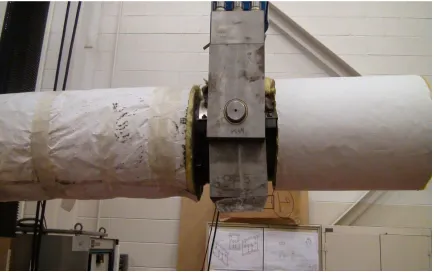
The pipe tests were conducted in Battelle’s Fatigue and Structures Laboratory
using the 500 kip MTS fatigue machine as a load frame seen in Figure 3.2. The test was
performed on an unpressurized pipe at 315C (600F). The inner span for the 4-point bend
loading is 1.32 m (52 inches). The outer span is 3.15 m (124 inches). For the load frame
shown in Figure 3.3, the inner two rams pulled down on the pipe, putting the bottom half
of the pipe in tension. The crack is located on the bottom of the pipe centered laterally
37
Figure 3.2. 500 kip MTS servo-hydraulically controlled test frame in Battelle’s Fatigue and Structures Laboratory.
38
During some initial load testing it was found that the outer saddle, Figure 3.4,
could slide in some instances making the data more difficult to analyze. Thus, going
forward, slide limiters were welded on to the pipe to prevent the saddles from moving
while the pipe is loaded.
Figure 3.4. Outer saddle.
A large amount of data was collected during this test. Video data of crack growth
was recorded during the entire test recording the crack growth as seen in Figure 3.5. The
instrumentation plan for the complex cracks and through wall cracks are the same. The
data collected during the cracked pipe experiments included the following:
The applied load at each of the 4 load points.
39
The displacement at the crack plane with respect to the load frame, made with a
string potentiometer.
Rotations (using inclinometers) of each of the 4 load points.
Crack mouth opening displacements (CMOD) at the crack centerline and both of
the initial through-wall crack tips. Clip gages will be used to measure the CMOD
data. Figure 3.6 is a photo of the clip gage that is used in this experiment.
Crack initiation using electrical potential.
Electric potential probes is applied across the crack at the crack centerline and
both of the initial through-wall crack tip locations on the outside pipe surface. In
addition, there will be a location where the base metal electric potential data will
be measured.
Pipe rotation data using inclinometers mounted on the top of the pipe on either
side of the test weld will be measured.
40 Figure 3.5. Video still from DMW 4 pipe test.
41
3.2.2SPECIMEN PARAMETERS
The pipe specifications for this experiment are similar to that used in common
reactor applications. However, some variance is expected because the pipe was not
necessarily manufactured at the same facility as the pipe that is used in reactor
applications. The potential slight difference in materials is believed to have minimal
impact on the correlations and estimation solutions that are developed as a result of the
experiment. Some of the important pipe parameters for this test are:
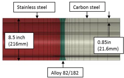
• 8 inch diameter Schedule 160 pipe nominally 8.625 inches OD with a wall
thickness of 0.85 inches (Normally 8 inch Schedule 160 pipe is 0.906 inches
thick but for this experiment the ID has been machined to yield a uniform wall
thickness)
• The weld OD and ID have also been machined to remove the weld crown and
any burn through on the ID
• Welds join sections of a high strength A106C carbon steel pipe to Type 316
stainless steel pipe; this particular A106C pipe has strength properties at
temperature (600 F) that approach those of A508 Grade 2 material
• Butter applied using SMAW Inconel 182 stick
• Buttered carbon steel pipe post-weld heat treated
• Main weld made using GTAW Inconel 82 weld wire
Property tests were performed on the material used in this experiment to obtain
material/test specific properties. Ramberg-Osgood parameters were also determined
42
Table 3.1. Material properties for carbon and stainless steel.
3.2.3SPECIMEN FABRICATION
This experiment required the fabrication of thirteen different pipes with DM
welds. Of the 13 fabricated pipes, seven were machined with CCs, one with a pure SC,
and five with TWCs. The cracks in each experiment are located either in the main weld,
the butter, or along the fusion line between the carbon steel pipe material and the inconel
butter. The CCs were machined with different SC depths; a shallow crack (20% of the
wall thickness), an intermediate crack (40% of the wall thickness) and a deep crack (60%
of the wall thickness). DMW 13 was cycled to create a sharp crack tip, while the other
experiments were not and are not considered to have a sharp crack tip. For the CCs and
the TWC experiments, the fraction of circumference that was machined as a TWC was
20% for one pipe and 37% for the other TWCs and CCs. The choice of a 37% TWC and
the depth of SCs were selected because they are similar to many of the previous
experiments that were performed by Battelle and also to limit the load application
requirements for the experimental setup. Thus, this will simplify the comparison of
results to previously performed single metal fracture experiments.
SS side of specimen CS side of specimen Inconnel (82, 182)
σy(psi) 22600 42000 46400
σu(psi) 68700 89200 81300
E(psi) 2.50E+07 2.80E+07 2.95E+07
σ0 22600 42000 46400
ϵo 0.000904 0.0015 0.001573
α 3.35 4.22 4.45
n 10.1 2.16 6.31
43
For the CC specimens the internal SC was machined first. This SC was machined
using a vertical machining cutter using a tapered blade, see Figure 3.7.
Figure 3.7. Blades used in machining the internal SC.
After the SC was machined, the bulk of the TWC was introduced using a wire cut
electro-discharge-machining (EDM) process. The tips of the TWC were sharpened using
a plunge EDM process with a tapered electrode as shown in Figure 3.8 and Figure 3.9.
The shape of the electrode was designed to eliminate the sharp corner at the interface of
44
Figure 3.8. EDM cutter being used to create a TWC in the pipe.
Figure 3.9. Picture of electrode used in EDM process with electrode design feature used to reduce taper circled.
Following the completion of the machining process of the test pipe section, the
45
required to obtain the data listed in 3.2.1. Next, the moment arms were welded onto the
test specimens then the pipe was placed into the strongback and saddles and the exterior
of the pipe instrumented. Finally the instrumentation was hooked up to the data
acquisition system.
3.3TEST PLAN
Table 3.2 lists the number and combination of experiments that were performed
based on the three key variables; type of crack, location, and size of crack. The
combination of different variables were developed using the lessons learned from past
base metal complex crack-shaped experiments. In addition, companion laboratory-sized
46
Table 3.2. Test matrix of DM weld pipe experiments.
Experiment Number Type of Crack Crack Location Surface Crack a/t Surface Crack θ/π TWC θ/π
DMW-0 Uncracked N/A N/A N/A N/A
DMW-1 Complex Crack
Weld 0.2 1.0 0.37
DMW-2 Complex Crack
Weld 0.4 1.0 0.37
DMW-3 Complex Crack
Weld 0.6 1.0 0.37
DMW-4 Complex Crack
Butter 0.2 1.0 0.37
DMW-5 Complex Crack
Butter 0.4 1.0 0.37
DMW-6 TWC Weld N/A N/A 0.20
DMW-7 Complex Crack
Fusion Line
0.2 1.0 0.37
DMW-8 Complex Crack
Fusion Line
0.4 1.0 0.37
DMW-9 TWC Butter N/A N/A 0.37
DMW-10 TWC Weld N/A N/A 0.37
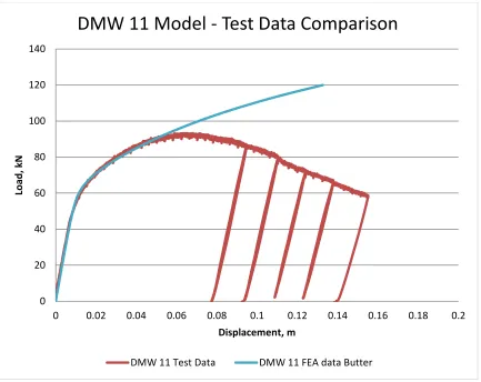
DMW-11 TWC Weld N/A N/A 0.37
DMW-12 Surface Crack
Weld 0.6 1.0 N/A
DMW-13 TWC
(fatigue precracked)
Weld N/A N/A 0.37
The test matrix includes 13 cracked pipe fracture experiments plus one uncracked
experiment. The uncracked experiment was performed to ensure that the experimental
facility functions as expected, primarily establishing that the data acquisition system is
functioning properly. The calibration of all instrumentation is traceable back to the
National Institute of Standards and Technology (NIST). In addition all tests were:
![Figure 1.2. A typical weld for a VHP. [37]](https://thumb-us.123doks.com/thumbv2/123dok_us/8453701.1389229/20.612.105.494.317.647/figure-typical-weld-vhp.webp)