A comparative Performance Analysis of 4x4
MIMO-OFDM system using Spatial
Multiplexing under various Wireless Channels
Kishore Kumar Mali
M.Tech. Scholar, Department of ECE, College of Technology and Engineering, Udaipur, Rajasthan, India
Abstract— Multiple Input Multiple Output (MIMO) technology refers to wireless communication systems employing multiple antennas at either the transmitter end or the receiver end or both. In recent times, use of multiple transmit and receive antenna for enhancing spectral efficiency in a wireless system has established much interest in research field. The solution to obtain superior data rates and better range performance at the same time is OFDM integrated with MIMO technique which is based on IEEE 802.11n standard. The main trouble in front of the wireless multipath propagation is the interference between information symbols transmitted through neighbouring channels also called as Inter Symbol Interference (ISI). This could be avoided if we use OFDM technology. Thus MIMO combined with OFDM has got significant importance in future wireless communication system. The major properties of MIMO system involve Spatial Diversity and Spatial Multiplexing which are the main factors to discuss and matter of concern to achieve reliability and high speed data rate. In this paper, we study the performance gain of MIMO-OFDM systems. The main investigation carried out in the following paper is to deal with various Wireless channel models in Spatial Multiplexing (SM) mode. The paper deals with MIMO-OFDM system analysis in various Wireless channel models (Rayleigh, Rician, Nakagami and 3GPP channel Environment) focusing on error rate performance, throughput and Spectral gain in 4x4 MIMO scheme under OFDM system. Evaluation of Bit Error Rate and throughput with respect to varying Eb/No for 4x4 MIMO-OFDM in Spatial Multiplexing mode, employing 16 QAM modulation with N=128 OFDM subcarriers employing MMSE detection, is the baseline of this paper.
Keywords— 3GPP, MIMO, MMSE, OFDM, QAM, SM, Eb/No
I. INTRODUCTION
Next generation wireless communication system will demand purely high speed communication links, high quality multimedia and data services with high efficiency
and reliability. In order to achieve high bit data rate services such as online gaming, video conferencing or web browsing, the next generation wireless communication systems would have to improve their range, quality of service (QoS), bandwidth, throughput and power efficiency [1]. MIMO has been standardized for 3G, 4G wireless LANs and is now in far flung commercial use. Multiple Input Multiple Output technology has achieved widespread attention in recent years as a promising wireless technology. Such systems offer the dual benefits of wireless channel fading mitigation through diversity reception and link throughput enhancement through Spatial Multiplexing [2]. The SM is typically well suited to users with good channel conditions that is, to users near the cell centre with a high signal-to-noise ratio [3]. One of the most key feature of wireless channels is Multipath propagation. The faster the data rate, the higher the probability that multipath propagation will cause Inter Symbol Interference (ISI) [2]. Due to the multipath propagation, signal suffers rapid and severe fluctuations in amplitude and phase. The solution to obtain noteworthy superior data rates and enhanced range performance at the same time is MIMO-OFDM which is based on 802.11n standard. This increases the link capacity by concurrently transmitting multiple data streams using multiple transmit and receive antennas. OFDM is the technique which is used to mitigate the multipath propagation problem and MIMO is useful for the efficient usage of spectral bandwidth thus combining these techniques results in wireless system that has best spectral coverage, reliable transmission in highly obstructive wireless environment. By multiplying spectral efficiency, MIMO-OFDM opens the door to a range of new applications and enables more cost-effective implementation for existing applications [4].
II. OVERVIEW OF SPATIAL MULTIPLEXING MODE (SM)
Spatial multiplexing obeys space-time diversity technique whose foundation design is to transmit independent information links from each transmit antenna. Spatial multiplexing can offer an increase in the transmission rate and spectral efficiency, because each spatial channel carries independent data, thereby escalating the data rate of the system. To achieve this goal, we may opt to place different portions of the information on different spatial paths, providing improved data rate of the system. spatial multiplexing, if the scattering by the environment is well enough, multiple independent spatial links are formed in the same allocated bandwidth. Thus the multiplexing gain, also referred as number of deg freedom, comes at no extra cost on bandwidth or power. Multiplexing gain or degrees of freedom in a MIMO configuration is equal to min (m,n) where m is the number of transmit antennas and n is the number of receive antennas [5].
Fig. 2 displays a simple spatial multiplexing system using a 2x2 MIMO system. In this study, the first information symbol, s0, is transmitted from the transmit antenna Tx0, and the second information symbol, s1, is transmitted from transmit antenna, Tx1. During the first symb the propagation of these two data symbols occurs concurrently. The data symbols s2 and s3 are concurrently transmitted during the next symbol time. In this action, alternate symbols are sent from each antenna and each symbol is only transmitted once, providing doubled data rate. Compared to STC, this technique is entirely different as no information symbols are repeated over two symbol times across the two antennas. Here, it is assumed that antennas are properly placed so that fading coefficients are different. A complex wireless fading coefficient h00 exist between Tx0 to Rx0. A complex wireless fading coefficient h10 exist between Tx0 to Rx1
analogous relationship between Tx1 and the remaining two receive antennas resulting four non-identical complex fading coefficients h00, h01, h10 and h11 [6].
After transmitting all the data symbols through the channel using spatial multiplexing, the receiver receive the signal r0, at antenna Rx0, as an addition of the s s1 information symbols, corrupted with complex fading coefficients H00 and H01 respectively. Concurrently, the Rx1 receives s0 and s1 affected with complex fading coefficients, H10 and H11 respectively. Here, we are neglecting the effect of noise. Therefore received signal at each received antenna can be modeled as
… 1 … 2
OVERVIEW OF SPATIAL MULTIPLEXING MODE (SM)
time diversity technique whose foundation design is to transmit independent information links from each transmit antenna. Spatial ransmission rate each spatial channel , thereby escalating the data rate of the system. To achieve this goal, we may opt to place on different spatial viding improved data rate of the system. In spatial multiplexing, if the scattering by the environment is well enough, multiple independent spatial links are formed in the same allocated bandwidth. Thus the multiplexing gain, also referred as number of degree of freedom, comes at no extra cost on bandwidth or power. Multiplexing gain or degrees of freedom in a MIMO configuration is equal to min (m,n) where m is the number of transmit antennas and n is the number of
mple spatial multiplexing system using a 2x2 MIMO system. In this study, the first information symbol, s0, is transmitted from the transmit antenna Tx0, and the second information symbol, s1, is transmitted from transmit antenna, Tx1. During the first symbol time the propagation of these two data symbols occurs concurrently. The data symbols s2 and s3 are concurrently transmitted during the next symbol time. In this action, alternate symbols are sent from each antenna and each e, providing doubled data Compared to STC, this technique is entirely different as no information symbols are repeated over two symbol Here, it is assumed that antennas are properly placed so that fading coefficients are different. A complex wireless fading coefficient h00 A complex wireless fading coefficient h10 exist between Tx0 to Rx1. There is an relationship between Tx1 and the remaining identical complex fading coefficients h00, h01, h10 and h11 [6].
After transmitting all the data symbols through the channel using spatial multiplexing, the receiver receives the signal r0, at antenna Rx0, as an addition of the s0 and information symbols, corrupted with complex fading respectively. Concurrently, the affected with complex fading respectively. Here, we are Therefore received signal at
The spatial signatures of the two signals, r0 and r1 are separated under favourable
section, having knowledge of the channel state, can easily recover symbols s0 and s1by further signal processing. If there are m transmit antenna a
equation can be rewritten in the following matrix form,
... .
…
... . ....
…
In order to recover the information from the received signals, the channel coefficient matrix [H] needs to be inverted. The matrix inversion becomes difficult if the channel coefficients in [H] are highly correlated [6].
Fig. 1: 2x2 MIMO systems employing Spatial Multiplexing
III. MIMO WITH ORTHOGONAL FREQUENCY DIVISION
The motivation behind the MIMO system is to achieve higher throughput and the motivation behind the OFDM system is to convert frequency selective into set of parallel flat fading channels. OFDM compensates for Inter symbol Interference (ISI),
for its diversity/multiplexing benefits. So we couple the ability of both the system to achieve high throughput as well as simplified processing at the receiver that is converting the frequency selective channel into the set of parallel flat fading channels. Hence, MIMO
combination MIMO communication with OFDM. Similar to OFDM, MIMO-OFDM converts a frequency selective MIMO channel into multiple parallel flat fading channels. From the theory of OFDM, in a MIMO
IDFT and IFFT operation has to be performed at each transmit antenna. Multiple Transmit antennas are used to transmit data modulated by OFDM in a MIMO
system. At the receiver, after OFDM demodulation, the signal are detected back by decoding every sub
from all the transmit antennas [7].
The spatial signatures of the two signals, r0 and r1 are favourable conditions. The receiver section, having knowledge of the channel state, can easily recover symbols s0 and s1by further signal processing. If there are m transmit antenna and n receive antenna then equation can be rewritten in the following matrix form,
...
. .... .... … 3
In order to recover the information from the received e channel coefficient matrix [H] needs to be inverted. The matrix inversion becomes difficult if the channel coefficients in [H] are highly correlated [6].
Fig. 1: 2x2 MIMO systems employing Spatial Multiplexing
MIMO WITH ORTHOGONAL FREQUENCY DIVISION MULTIPLEXING
3.1 MIMO-OFDM Operations 3.1.1 Transmitter Section
S/P Demux for Transmit Antennas: Serial to parallel Demultiplexing of the data bits for the transmit antennas.
16-QAM Modulator: It converts the data into a sequence of modulated symbols in complex format. S/P Demux: On each transmit antenna, symbols are again demultiplexed for further IFFT operation. N pt IFFT: On Each block of symbol, N point IFFT is
performed. IFFT operation is used to shift the signal from time domain to frequency domain. It takes N input symbols at one time where N is the number of subcarriers in the system.
P/S: After N point IFFT, symbols are multiplexed by parallel to serial convertor.
CP: The symbols are added with cyclic prefix.
Fig. 2: OFDM signal with cyclic prefix
By this manner, each symbol is processed and transmitted to tth antennas.
3.1.2 Receiver Section
In the similar fashion corresponding receiver operations are performed in MIMO-OFDM.
CP: Added Cyclic prefix are removed from the symbols.
Fig. 3: Removal of cyclic prefix from OFDM signal 16-QAM Demodulator: It converts modulated data into a sequence of demodulated symbols.
S/P Demux: On each receive antenna, symbols are demultiplexed for further FFT operation.
N pt FFT: On Each block of symbol, N point FFT is performed. FFT block is employed to shift the received time-domain signal into frequency
MIMO Detection: On each OFDM sub MIMO detection is performed. Appropriate technique is employed on each OFDM subcarriers. P/S Mux: After MIMO detection, symbols are multiplexed by parallel to serial convertor. Corresponding symbol blocks are decoded at P/S Demultiplexer.
S/P Demux for Transmit Antennas: Serial to parallel Demultiplexing of the data bits for the transmit
QAM Modulator: It converts the data into a ence of modulated symbols in complex format. S/P Demux: On each transmit antenna, symbols are again demultiplexed for further IFFT operation. N pt IFFT: On Each block of symbol, N point IFFT is
performed. IFFT operation is used to shift the signal e domain to frequency domain. It takes N input symbols at one time where N is the number of
P/S: After N point IFFT, symbols are multiplexed by
CP: The symbols are added with cyclic prefix.
OFDM signal with cyclic prefix
By this manner, each symbol is processed and transmitted
In the similar fashion corresponding receiver operations
CP: Added Cyclic prefix are removed from the
cyclic prefix from OFDM signal QAM Demodulator: It converts modulated data into a sequence of demodulated symbols.
S/P Demux: On each receive antenna, symbols are for further FFT operation.
N pt FFT: On Each block of symbol, N point FFT is performed. FFT block is employed to shift the domain signal into frequency-domain. MIMO Detection: On each OFDM sub-channel MIMO detection is performed. Appropriate detection technique is employed on each OFDM subcarriers. P/S Mux: After MIMO detection, symbols are multiplexed by parallel to serial convertor. Corresponding symbol blocks are decoded at P/S
IV. FLOW CHART OF THE PROPOSED
Fig. 4: Algorithm flowchart
Transmitter
Section
OFDM symbols corrupted by channel H
and AWGN noise
Generate channel coefficients
Append cyclic prefix
IFFT operation
Generate Transmit signal vectors for
Transmit Antennas
Create Modulation Object
Generate Random Stream for channel
Define QAM Modulation order
Specify Bit Energy to Noise Ratio
Specify Number of Subcarriers
Input the Number of Transmit and Receive
Antennas
Receiver
Section
BER and Throughput Calculation
MIMO-MMSE Detection
FFT operation
Create Demodulation Object
Remove cyclic prefix
FLOW CHART OF THE PROPOSED WORK
Algorithm flowchart
Transmitter
Section
OFDM symbols corrupted by channel H
and AWGN noise
Generate channel coefficients
Append cyclic prefix
IFFT operation
Generate Transmit signal vectors for
Transmit Antennas
Create Modulation Object
Generate Random Stream for channel
Define QAM Modulation order
Specify Bit Energy to Noise Ratio
Specify Number of Subcarriers
Input the Number of Transmit and Receive
Antennas
Receiver
Section
BER and Throughput Calculation
MMSE Detection
FFT operation
V. SIMULATION PARAMETERS AND RESULTS
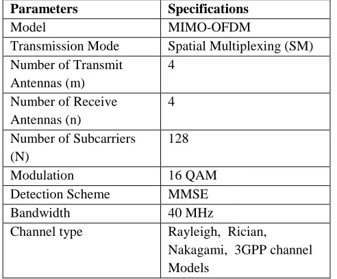
In the following analysis, a 4x4 configuration for MIMO OFDM is incorporated i.e. m=4 transmit antennas and n=4 receive antennas. This simulation analysis integrates baseband transmission with MIMO-OFDM using 40MHz bandwidth. The Eb/No assessments are divided into three categories i.e. low Eb/No (1-5) dB, medium Eb/No (5 dB and high Eb/No (>10) dB. Table 1 enlists the simulation parameters and their corresponding specifications.
Table 1: Simulation parameters
Parameters Specifications
Model MIMO-OFDM
Transmission Mode Spatial Multiplexing (SM) Number of Transmit
Antennas (m)
4
Number of Receive Antennas (n)
4
Number of Subcarriers (N)
128
Modulation 16 QAM
Detection Scheme MMSE
Bandwidth 40 MHz
Channel type Rayleigh, Rician,
Nakagami, 3GPP channel Models
5.1 Comparative analysis of BER vs Eb/No under various Wireless channels in a
MIMO-with m=n=4 in SM Mode MIMO-with N=128 Subcarriers
Fig. 5: Comparative analysis of BER vs Eb/No for MIMO-OFDM-SM system under various Wireless
channel Environment
In the following observation, the comparative analysis of BER vs Eb/No for various Wireless channels for a
SIMULATION PARAMETERS AND
In the following analysis, a 4x4 configuration for MIMO-OFDM is incorporated i.e. m=4 transmit antennas and
analysis integrates OFDM using 40MHz bandwidth. The Eb/No assessments are divided into three 5) dB, medium Eb/No (5-10) dB and high Eb/No (>10) dB. Table 1 enlists the heir corresponding
Table 1: Simulation parameters
Specifications
OFDM
Spatial Multiplexing (SM)
Rayleigh, Rician,
Nakagami, 3GPP channel
5.1 Comparative analysis of BER vs Eb/No under -OFDM system Subcarriers
Fig. 5: Comparative analysis of BER vs Eb/No for SM system under various Wireless
In the following observation, the comparative analysis of BER vs Eb/No for various Wireless channels for a
MIMO-OFDM system with carried out with N=128 subcarriers.
An alluring observation in this fig. 5 is that simulation result with respect to BER in Rician fading channel is better than Rayleigh, Nakagami, Sub-Urban Macrocell, Urban Macrocell and Urban Microcell channel Environment respectively.
A very significant amount of performance improvement in terms of BER is observed in Rayleigh and Rician fading channels, when the system embedded with N=128 subcarriers is utilized in low Eb/No region (1
conditions deteriorates or in a scenario where the signal component is bound to experience distortion and deep fading.
It is noteworthy to observe that in Nakagami, Sub Urban Macrocell, Urban Macrocell and Urban Microcell channel Environment, system e
N=128 subcarriers provides significant reduction in BER in medium Eb/No region (5
It is observed that Rician fading Environment achieved BER of 10-4
Rayleigh fading Environment achieved BER of 10 at 4.5 dB. For Nakagami, Sub
Urban Macrocell and Urban Microcell channel Environment BER of 10
dB, 7.2 dB and 9 dB respectively.
Another appealing observation in this fig. 5 is that in Rician fading channel BER of 10
dB which provides best result. In Nakagami fading channel BER of 10-4 is achieved at 6.5 dB which provides moderate result and Urban Microcell channel Environment achieved BER of 10
which provides poorest result among all channel environments. Table 2 enlists the required Eb/No to reach a target BER of 10
Table 2: Comparative analysis of required Eb/No to reach a target BER of 10
channel
Channel Environment
EB/No (dB)
Rician 3.3
Nakagami 6.5 Urban Microcell 9
5.2 Comparative analysis of Throughput vs Eb/No under various Wireless channels in a MIMO
system with m=n=4 in SM mode with N=128 Subcarriers
The following observation illustrates the comparative analysis of Throughput vs Eb/No for various Wireless OFDM system with m=n=4 in SM Mode is carried out with N=128 subcarriers.
An alluring observation in this fig. 5 is that simulation result with respect to BER in Rician fading channel is better than Rayleigh, Nakagami, Urban Macrocell, Urban Macrocell and Urban
ll channel Environment respectively.
A very significant amount of performance improvement in terms of BER is observed in Rayleigh and Rician fading channels, when the system embedded with N=128 subcarriers is utilized in low Eb/No region (1-5) dB where channel conditions deteriorates or in a scenario where the signal component is bound to experience distortion
It is noteworthy to observe that in Nakagami, Sub-Urban Macrocell, Sub-Urban Macrocell and Sub-Urban Microcell channel Environment, system enabled with N=128 subcarriers provides significant reduction in BER in medium Eb/No region (5-10) dB.
It is observed that Rician fading Environment at nearly 3.3 dB whereas Rayleigh fading Environment achieved BER of 10-4
r Nakagami, Sub-Urban Macrocell, Urban Macrocell and Urban Microcell channel Environment BER of 10-4 is achieved at 6.5 dB, 7 dB, 7.2 dB and 9 dB respectively.
Another appealing observation in this fig. 5 is that in Rician fading channel BER of 10-4 is achieved at 3.3 dB which provides best result. In Nakagami fading is achieved at 6.5 dB which provides moderate result and Urban Microcell channel Environment achieved BER of 10-4 at 9 dB which provides poorest result among all channel ironments. Table 2 enlists the required Eb/No to reach a target BER of 10-4 among all channels.
Table 2: Comparative analysis of required Eb/No to reach a target BER of 10-4 under different Wireless
channel
EB/No (dB) Performance
Best Moderate Worst
5.2 Comparative analysis of Throughput vs Eb/No under various Wireless channels in a MIMO-OFDM system with m=n=4 in SM mode with N=128
channels in a MIMO-OFDM system with m=n=4 in SM mode with N=128 subcarriers.
It can be clearly seen from the fig. 6 that the simulation result of throughput in Rician fading channel is better than Rayleigh, Nakagami, Sub Urban Macrocell, Urban Macrocell and Urban Microcell channel Environment respectively.
As it can be observed that in Rician fading channel, maximum throughput is achieved at 4 dB wher Rayleigh fading channel maximum throughput is achieved at 6 dB. For Nakagami, Sub Macrocell, Urban Macrocell and Urban Microcell channel Environment maximum throughput is achieved at 8 dB, 8 dB, 9 dB and 10 dB respectively.
Fig. 6: Comparative analysis of Throughput vs Eb/No for MIMO-OFDM-SM system under various Wireless
channel
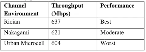
An enthralling observation in this fig. 6 is that Rician fading channel achieves maximum throughput at lowest Eb/No of 4 dB, providing best result. In Nakagami and Sub-Urban Macrocell Environment, maximum throughput is achieved at 8 dB. Urban Microcell channel Environment achieves maximum throughput at Eb/No of 10 dB which is greatest from all channels, providing worst result.
Table 3: Comparative analysis of variation of minimum throughput among different channel Environment
Channel Environment
Throughput (Mbps)
Performance
Rician 637 Best
Nakagami 621 Moderate
Urban Microcell 604 Worst
OFDM system with m=n=4 in SM
It can be clearly seen from the fig. 6 that the oughput in Rician fading channel is better than Rayleigh, Nakagami, Sub- Urban Macrocell, Urban Macrocell and Urban Microcell channel Environment respectively.
As it can be observed that in Rician fading channel, maximum throughput is achieved at 4 dB whereas in Rayleigh fading channel maximum throughput is achieved at 6 dB. For Nakagami, Sub-Urban Macrocell, Urban Macrocell and Urban Microcell channel Environment maximum throughput is achieved at 8 dB, 8 dB, 9 dB and 10 dB respectively.
ive analysis of Throughput vs Eb/No for SM system under various Wireless
An enthralling observation in this fig. 6 is that Rician fading channel achieves maximum throughput at lowest Eb/No of 4 dB, providing best result. In Urban Macrocell Environment, maximum throughput is achieved at 8 dB. Urban Microcell channel Environment achieves maximum throughput at Eb/No of 10 dB which is greatest from
tion of minimum throughput among different channel Environment
Performance
Best
Moderate
Worst
VI. CONCLUSION
In this paper, the Performance analysis in terms of BER and Throughput in MIMO Spatial Multiplexing integrated with OFDM system for various Wireless channel models has been addressed. In SM mode, when number of subcarriers (N=128) was employed then Rician fading Environment achieved BER of 10
provides best result. In Nakagami fading Environment BER of 10-4 is achieved at 6.5 dB which provides moderate result and Urban Microcell channel Environment achieved BER of 10
provides poorest result among all channel environments. A very significant amount of performance improvement in terms of BER is observed in Rayleigh and Rician fading channels, when the system embedded with N=128 subcarriers is utilized in low Eb/No region (1
channel conditions deteriorates or in a scenario wh signal component is bound to experience distortion and deep fading. In Nakagami, Sub
Macrocell and Urban Microcell channel Environment, system enabled with N=128 subcarriers provides significant reduction in BER in medium Eb/
10) dB. It was also found that the minimum throughput offered by the system changes with variation in the channel environment in SM mode. It was observed that by increasing the number of subcarriers (N), Eb/No decreases at the same Bit Error
REFERENCES
[1] K. Volker. “Wireless Communications over MIMO Channels Application to CDMA and Multiple Antenna Systems”, Rostock University, Germany, John Wiley and Sons Ltd.
[2] E. Biglieri, R. Calderbank, A. Constantinides, A. Goldsmith, A. Paulraj and H
Communications”. Published in the United States of America by Cambridge University Press, New York. [3] R. Suthar, P.C. Bapna and S. Joshi. “A Comparative
Performance Analysis of Spatial Multiplexing and Transmit Diversity Approaches for
Correlation based Channel”. In: Proceedings of International Journal of Computer Applications (0975 – 8887), 2014.
[4] M. Gulzar, R. Nawaz and D. Thapa. “Implementation of MIMO
WiMAX”. Master’s Thesis, Linnaus University, Kalmar, 2011.
[5] L. Zheng and D. Tse. “Diversity and Multiplexing: A Fundamental Tradeoff in Multiple
Channels”. In: Proceedings of IEEE transactions on Information Theory, Vol. 49, No. 5, May 2003.
CONCLUSION
In this paper, the Performance analysis in terms of BER Throughput in MIMO Spatial Multiplexing integrated with OFDM system for various Wireless channel models has been addressed. In SM mode, when number of subcarriers (N=128) was employed then Rician fading Environment achieved BER of 10-4 at 3.3 dB which ides best result. In Nakagami fading Environment is achieved at 6.5 dB which provides moderate result and Urban Microcell channel Environment achieved BER of 10-4 at 9 dB which provides poorest result among all channel environments.
ificant amount of performance improvement in terms of BER is observed in Rayleigh and Rician fading channels, when the system embedded with N=128 subcarriers is utilized in low Eb/No region (1-5) dB where channel conditions deteriorates or in a scenario where the signal component is bound to experience distortion and deep fading. In Nakagami, Sub-Urban Macrocell, Urban Macrocell and Urban Microcell channel Environment, system enabled with N=128 subcarriers provides significant reduction in BER in medium Eb/No region (5-10) dB. It was also found that the minimum throughput offered by the system changes with variation in the channel environment in SM mode. It was observed that by increasing the number of subcarriers (N), Eb/No decreases at the same Bit Error Rate.
REFERENCES
K. Volker. “Wireless Communications over MIMO Channels Application to CDMA and Multiple Antenna Systems”, Rostock University, Germany, John Wiley and Sons Ltd.
E. Biglieri, R. Calderbank, A. Constantinides, A. Goldsmith, A. Paulraj and H. Poor. “MIMO Wireless Communications”. Published in the United States of America by Cambridge University Press, New York. R. Suthar, P.C. Bapna and S. Joshi. “A Comparative Performance Analysis of Spatial Multiplexing and Transmit Diversity Approaches for 2X2 LTE Correlation based Channel”. In: Proceedings of nternational Journal of Computer Applications
M. Gulzar, R. Nawaz and D. Thapa. “Implementation of MIMO-OFDM System for WiMAX”. Master’s Thesis, Linnaus University,
[6] Agilent Technologies, Inc. 2010. “Agilent MIMO Channel Modeling and Emulation Test Challenges” Printed in USA, January 22, 2010, 5989-8973EN [7] Y. Cho, J. Kim, W. Yang and C. Kang.