A Novel PSO-Based Transfer Efficiency Optimization Algorithm
for Wireless Power Transfer
Meng Wang1, Jing Feng1, Yanyan Shi1, *, Minghui Shen2, and Jianwei Jing1
Abstract—To improve the power transfer efficiency in a magnetically-coupled resonant wireless power transfer (MCR-WPT) system, an efficient particle swarm optimization (PSO) algorithm based on the change of particle swarm scale is proposed. The transfer efficiency and frequency are used as the fitness function and particle position, respectively. Therefore, the optimal frequency can be obtained by adjusting the position of particle. Five types of optimizing process are presented and compared with the traditional PSO algorithm. It is found that the proposed method has faster convergence speed than the traditional PSO algorithm. Additionally, the proposed five types of optimizing process with different regulation parameters are investigated. The results indicate that Type 2 with n = 3 is the best alternative in finding the optimal frequency with the fastest speed of convergence. Experimental prototypes have been set up for validation.
1. INTRODUCTION
Magnetically-coupled resonant wireless power transfer (MCR-WPT) makes it possible to transmit electrical energy in the mid-range without direct wire connection [1–4]. It has been indicated that MCR-WPT can be widely applied in consumer electronics, biomedical applications and portable devices in the near future [5–7]. There have been extensive reports on the theoretical analysis for MCR-WPT system using the coupled mode theory, finite element analysis method and circuit theory [8, 9]. It is well known that MCR-WPT operating at a fixed frequency suffers from dramatic variation of power transfer efficiency when the distance between transmitting coil (Tx) and receiving coil (Rx) varies [10]. The optimal transfer efficiency is obtained at the original resonant frequency when the transfer distance is larger than a critical distance [11–13]. In other case, the transfer efficiency is maximal at two different frequencies where frequency splitting occurs. The influence of transfer efficiency is analyzed in [14], and it is found that transfer performance can be improved by using different frequencies according to the transfer distance. In addition, a tunable impedance matching network is helpful to eliminate the frequency splitting in the over-coupled region [15–19]. However, both of the approaches are realized by adjusting complex circuit which makes it inconvenient for many applications. Changing the coil configuration is another method for higher transfer efficiency [20]. However, the efficiency in the long distance is decreased due to the weak coupling in the under-coupled region.
It has been revealed that the transmission efficiency of the MCR-WPT is merely dependent on the operating frequency once the parameters of the coils are determined, and the transfer distance is fixed. The relationship between them can be expressed as a function with one or two extreme points. In particle swarm optimization (PSO) algorithm, the value of fitness function is only affected by the particle position [21]. As a result, the transfer efficiency and operating frequency can be used as the
Received 20 April 2018, Accepted 25 June 2018, Scheduled 6 July 2018
* Corresponding author: Yanyan Shi ([email protected]).
fitness function and particle position, respectively. By searching for the optimal position of the particle, the frequency where the efficiency is maximal can be calculated.
In the traditional PSO algorithm, the problems of premature convergence or transient stagnation appear due to a large particle swarm scale, which results in redundant calculation or failing to find the optimal value in the global scope [22, 23]. In this paper, a novel PSO algorithm is proposed to solve the issue above. It is based on the change of the particle swarm scale by adjusting the particle number for a faster acquirement of the optimal results. At the beginning, the equivalent circuit model of MCR-WPT system is presented, and the power transfer efficiency and mutual inductance are calculated. After that, a novel PSO algorithm is presented, and the particle swarm scale, fitness function, and termination condition of the proposed algorithm are also studied for the MRC-WPT system with a fixed configuration of coils under different transfer distances. Then, the searching for optimal frequency in the MCR-WPT systems with or without frequency splitting is simulated. The theoretical analysis is experimentally validated. Finally, concluding remarks are drawn.
2. EQUIVALENT CIRCUIT MODEL FOR MRC-WPT
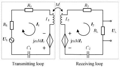
The equivalent circuit of MCR-WPT model is shown in Fig. 1. Both Tx and Rx can be described as self-inductance (L1, L2), capacitance (C1,C2) and resistance of the resonant coils (R1, R2) connected in series. US and RS indicate the voltage and internal resistance of the power source. RL is the load resistance andUL the voltage across the load. The mutual inductance M is introduced to describe the magnetic coupling between Tx and Rx.
Figure 1. Equivalent circuit model of MCR-WPT system.
For the WPT-MRC system shown in Fig. 1, the circuit equations of the system can be expressed
as
US =Z1I1−jωMI2 Z2I2−jωMI1 = 0 ,
(1)
where Z1 = RS+R1+j(ωL1 −1/ωC1), Z2 =RL+R2+j(ωL2−1/ωC2). I1 and I2 are the currents flowing in the transmitting loop and receiving loop respectively, andω is the operating frequency of the system.
Due to the identical configurations of Tx and Rx, it can be assumed that
R1 =R2 =R
C1 =C2 =C
L1=L2 =L ,
(2)
Additionally, RL is the same as RS (RS = RL = Z0) in this paper. According to Eq. (1) and Eq. (2), the transmission coefficient S21 can be calculated by [10, 24]:
S21= 2jωZ0M
(ωM)2+{(Z0+R) + j (ωL−1/ωC)}2. (3)
The transfer efficiencyη of the system can be expressed as [24]:
where|S21|is the magnitude of S21.
According to Eq. (3) and Eq. (4), the transfer efficiency is only dependent on operating frequency and mutual inductance when Tx and Rx are fixed.
For circular coils, the mutual inductance can be expressed as [24, 25]:
M = n1n2μ0π(r1r2) 2
2r12+d2
3/2 , (5)
where r1 and r2 are the radii of Tx and Rx, respectively; n1 and n2 are the numbers of turns for Tx and Rx;d is the axial distance between Tx and Rx.
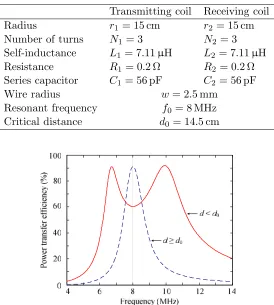
The parameters of the WPT-MRC system are listed in Table 1. Combining Eqs. (3), (4) and (5), the power transfer efficiency versus the operating frequency of the system is shown in Fig. 3. It should be noted that the resonant frequency of the MCR-WPT system is set to 8 MHz considering the stable operation of the power amplifier in this work.
Table 1. Parameters of MRC-WPT system.
Transmitting coil Receiving coil
Radius r1 = 15 cm r2 = 15 cm
Number of turns N1= 3 N2 = 3
Self-inductance L1= 7.11µH L2 = 7.11µH
Resistance R1 = 0.2 Ω R2 = 0.2 Ω
Series capacitor C1 = 56 pF C2 = 56 pF
Wire radius w= 2.5 mm
Resonant frequency f0= 8 MHz
Critical distance d0 = 14.5 cm
Figure 2. Power transfer efficiency versus operating frequency of system.
As shown in Fig. 2, it is obvious that frequency splitting appears when the transfer distance is smaller than the critical distance (d < d0). However, when the transfer distance is equal to or larger than the critical distance (d≥d0), the highest efficiency is achieved at the resonant frequency. Thus, the frequency of the system should be adjusted according to the transfer distance for a better performance.
3. A NOVEL PSO ALGORITHM
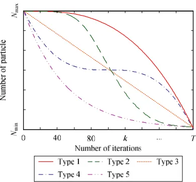
Figure 3. Particle number versus the number of iterations for five types of optimizing process.
and with slow convergence rate in the late process of the traditional PSO algorithm. Besides, the scale of particle swarm is uncertain for different objects, and there are no specific rules to obtain the exact particle number. A large particle number results in redundant computational cost while the optimal result cannot be acquired with a small particle number. In order to solve the problems of premature convergence or transient stagnation, a novel PSO algorithm is proposed to search for the optimal frequency of MCR-WPT based on the variation of particle swarm scale.
3.1. Analysis of Particle Swarm Scale
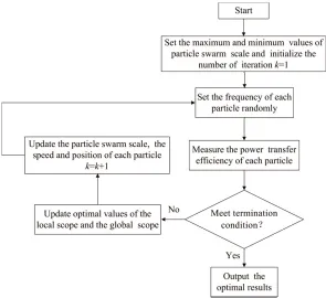
In the novel PSO algorithm, the maximum and minimum values of particle swarm scale are expressed as Nmaxand Nmin, respectively. In the algorithm, the particle numberN is randomly varied fromNmaxto Nmin as the number of iterationskincreases. Due to the large particle swarm scale in the early process, global scope is realized with the proposed algorithm. The particle swarm scale decreases randomly during the search process, which reduces the number of iterations and achieves a quick convergence.
In the process of optimization, particle swarm scale varies, and five types of particle swarm scale are investigated and expressed as:
⎧ ⎪ ⎪ ⎪ ⎪ ⎪ ⎪ ⎪ ⎪ ⎪ ⎨ ⎪ ⎪ ⎪ ⎪ ⎪ ⎪ ⎪ ⎪ ⎪ ⎩
N1= Nmax
12 (−(nk)/100) 3
+ Nmax
N2=Nmaxexp (−(1.13k/T)n) N3=Nmax−(Nmax−Nmin)nk/T
N4= Nmax
12 (−(nk−T/2)/100)
3+
Nmax
N5=Nmax(exp (−k/T))n
, (6)
whereNi(i= 1, 2, 3 ,4, 5) is the particle number of theith optimizing processes;kandT are the current number of iterations and the maximum value of iterations respectively; n is the regulation parameter used to control the change rate ofNi.
Different types of variation have a great effect on the optimization process. The particle number versus the number of iterations for five types of optimizing process is shown in Fig. 3.
3.2. Calculation of Fitness Function
In the study, the power transfer efficiency shown in Eq. (4) is used as fitness function in the proposed PSO algorithm. The fitness function is only dependent on the frequency of the power source when the transfer distance is fixed. Besides, the fitness function can be adjusted by substituting Eq. (5) to Eqs. (3) and (4) when transfer distance changes.
3.3. Analysis of Termination Strategy
Two kinds of termination strategy for the proposed PSO algorithm are presented:
(1) The maximum number of iterations Nmax is used as the condition of termination.
(2) The sum of variances σ2 is applied as the condition of termination. The value of σ2 can be calculated by:
σ2 = N
i
((fi−fa)/a)2, (7)
wherefi is the fitness of the current particle population, andfa is the average value of fi. In addition, if (fi−fa)>1,a= max(fi−fa). Otherwise,a= 1.
During the iterative process, the algorithm terminates whenσ2= 1∗10∧(−6) ork=Nmax. Then, the optimal frequency is obtained.
A flowchart of the algorithm is shown in Fig. 4.
Figure 4. Flow chat of the proposed algorithm.
4. NUMERICAL SIMULATION
is also studied, and the particle swarm scale is set to 30 according to the experience, training speed and accuracy. The internal resistance of the power sourceRS is 50 Ω, and the load resistanceRLis also set to 50 Ω. Transmitting coil and receiving coil are identical, and both of them are copper wire with wire radius w = 2.5 mm. The number of turns n1 = n2 = 3 and the radius r1 = r2 = 15 cm. Besides, the two coils are connected with capacitors in series for resonance.
4.1. Search for Optimal Frequency in System without Frequency Splitting
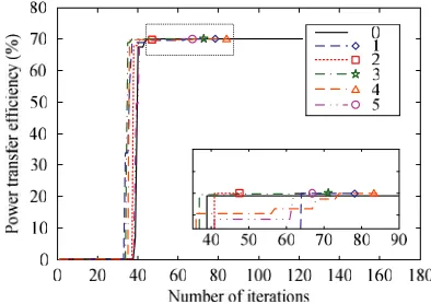
According to Eqs. (3), (4) and (5), the critical distance of the system is 14.5 cm. When the transfer distance d is set to 18 cm, the relationship between transfer efficiency and frequency can be expressed as the function with one extreme point. The power transfer efficiency versus the number of iterations is presented in Fig. 5. Number 0 represents the traditional PSO algorithm, and numbers 1, 2, 3, 4 and 5 represent five types of optimizing process proposed in this paper. In addition, different markers in the lines represent the end of algorithms.
Figure 5. Power transfer efficiency versus the number of iterations ford= 18 cm.
As shown in Fig. 5, identical results are obtained for different kinds of algorithms. The optimal frequency and the maximum value of power transfer efficiency are 8 MHz and 70.01%, respectively. For the traditional PSO algorithm, the optimal frequency is obtained when the number of iterations k is 122. However, k is far smaller than 122 in the proposed algorithm by using five types of optimizing process.
In addition, the convergence rate is different affected by the parameter n. For different n, the variation of power transfer efficiency against the number of iterations is shown in Fig. 6(a)–Fig. 6(e), and the variation of particle number against the number of iterations is shown in Fig. 6(f)–Fig. 6(j).
It can be seen from Fig. 6(a) and Fig. 6(f), the particle number changes slowly in the early process but changes dramatically in the late process for Type 1. Compared with n= 3 and n= 4, the particle number slowly decreases for n = 1 and n= 2. Besides, the optimal results for n= 1 and n = 2 have been obtained before the particle number decreases to the minimum. When n is set to 2, the number of iterations k is the smallest, and thus the optimal results can be achieved firstly. For Type 2 shown in Fig. 6(b) and Fig. 6(g), the rate of particle number change is small in the early and late processes but is large in the middle process. The number of iterations k is the smallest when n= 3. For Type 3 illustrated in Fig. 6(c) and Fig. 6(h), the optimal results can be firstly acquired when n is set to 2, and the number of iterations kis 56. For Type 4 shown in Fig. 6(d) and Fig. 6(i) and Type 5 shown in Fig. 6(e) and Fig. 6(j), the optimal results are obtained at the same nwhose value is 3. For five types of optimizing process, the numbers of iterations kare shown in Table 2.
(a)
(b)
(c)
(d)
(e)
(f)
(g)
(h)
(i)
(g)
Figure 6. Power transfer efficiency and particle number versus the number of iterations for different n.
Table 2. Number of iterations for five types of optimizing process.
Type 1 Type 2 Type 3 Type 4 Type 5
n= 1 99 120 70 180 82
n= 2 75 78 56 103 71
n= 3 127 42 83 90 59
n= 4 185 83 132 193 92
4.2. Search for Optimal Frequency in System with Frequency Splitting
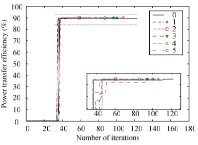
To investigate the performance of MCR-WPT system in the case of frequency splitting, the transfer distance is set to 10 cm, and then the relationship between power transfer efficiency and frequency can be expressed as the function with two extreme points. However, there is only one optimal frequency which corresponds to the maximum transfer efficiency as shown in Fig. 2. The transfer efficiency versus the number of iterations is shown in Fig. 7.
P
o
w
er tran
sfer e
ffi
ci
en
cy
(
%
)
Figure 7. Power transfer efficiency versus the number of iterations ford= 10 cm.
As shown in Fig. 7, identical results are obtained for different kinds of algorithms. The optimal frequency and maximum value of power transfer efficiency are 10.11 MHz and 93.75%, respectively. For the traditional PSO algorithm, the number of iterations k is 122. However, the convergence speed of five types of optimizing processes is faster than that of the traditional PSO algorithm.
For differentn, the variation of power transfer efficiency against the number of iterations is shown in Fig. 8(a)–Fig. 8(e), and the variation of particle number against the number of iterations is shown in Fig. 8(f)–Fig. 8(j).
It can be seen from Fig. 8(a) and Fig. 8(f), for Type 1, the optimal results can be obtained fastest when n is set to 2. Besides, for the case of n = 3 andn= 4 in Type 1, the particle number has been reduced to less than Nmin before the results could be obtained. For Type 2 illustrated in Fig. 8(b) and Fig. 8(g), the optimal results can be firstly achieved when nis set to 3, and the number of iterationsk is 47. For Type 3 shown in Fig. 8(c) and Fig. 8(h), the optimal results can be firstly obtained when n is set to 3, and the number of iterations kis 71. For Type 4 shown in Fig. 8(d) and Fig. 8(i) and Type 5 shown in Fig. 8(e) and Fig. 8(j), the optimal results are obtained first at the samen.
For five types of optimizing process in terms of frequency splitting, the number of iterations k is shown in Table 3.
As shown in Table 3, the number of iterations varies for five types of optimizing process and changes for the same type with differentn. Similar to the system without frequency splitting, Type 2 withn= 3 is also the best choice in all types of optimizing process to obtain the optimal results quickly.
Number of iterations Number of iterations
0 50 100
0 20 40 60 80 100
150 200 250 00 50 100 150 200 250
5 10 15 20 25 30
Number of iterations
0 50 100 150
0 20 40 50 80 100
0 50 100 150
0 5 10 15 20 25 30
Number of iterations 0 20 40 60 80 100
Number of iterations 0 5 10 15 20 25 30 n=1 n=2 n=3 n=4 n=1 n=2 n=3 n=4 60 100 n=1 n=2 n=3 n=4 n=1 n=2 n=3 n=4
40 80 120
n=1 n=2 n=3 n=4 n=1 n=2 n=3 n=4
40 80 120
Number of iterations
0 40 80 120 160 0 40 80 120 160
Nu mber of part ic le N um be r o f pa rti cle Po
wer transfer effi
ci en cy (% ) Po w er tr an sf er e ffi ciency (% ) (a) (b) (c) (d) (e) (f) (g) (h) (i) (g)
Figure 8. Power transfer efficiency and particle number versus the number of iterations for different n.
5. EXPERIMENTAL VALIDATION
Table 3. Number of iterations for five types of optimizing process.
Type 1 Type 2 Type 3 Type 4 Type 5
n= 1 103 105 103 115 108
n= 2 99 101 82 105 85
n= 3 116 47 71 79 73
n= 4 123 121 120 118 96
According to the transfer distance, the output frequency of the function generator is calculated by the proposed PSO algorithm operated with the upper computer. The experimental parameters of the resonant coils are the same as those listed in Table 1.
Figure 9. Photograph of experimental setup.
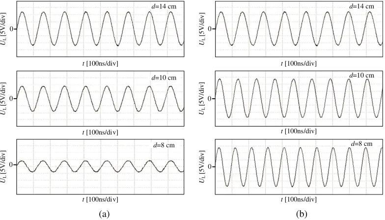
In the under-coupled region when dis larger than 14.5 cm, the resonant frequency is optimal for efficient wireless power transfer. As a result, Fig 10 only compares the variations of measured voltage at three different transfer distances in the over-coupled region when using the fixed resonant frequency and the proposed optimized PSO algorithm.
d=10 cm
d=14 cm
0
UL
[5V
/div]
t [100ns/div]
0
UL
[5
V/di
v
]
0
UL
[5V/
di
v
]
0
UL
[5V/
di
v
]
0
UL
[5V/
di
v
]
0
UL
[5
V/di
v
]
t[100ns/div]
t [100ns/div]
t [100ns/div]
t [100ns/div]
t [100ns/div]
d=8 cm
d=14 cm
d=10 cm
d=8 cm
(a) (b)
As shown in Fig. 10(a), the peak of voltage across load drops sharply from 12 V to 4.2 V as the transfer distance decreases from 14 cm to 8 cm. However, the voltage remains at a higher value in the MCR-WPT system using the proposed PSO algorithm when transfer distance changes. Especially in the near region, the peak of voltage increases to 14 V as shown in Fig. 10(b). This is because frequency splitting exists where the transfer efficiency occurs not at the original resonant frequency. In contrast, the optimal frequency at each transfer distance can be obtained with the proposed PSO algorithm eliminating the effect of frequency splitting.
Figure 11 shows the variation of transfer efficiency against the transfer distance for MCR-WPT system with the fixed frequency and MCR-WPT system with the proposed optimized PSO algorithm.
Figure 11. Power transfer efficiency versus transfer distance for MCR-WPT systems with the fixed resonant frequency and with the proposed optimized PSO algorithm.
As depicted in Fig. 11, the system efficiency gradually decreases when the transfer distance is larger than the critical distance for both of the systems. The MCR-WPT system with the proposed PSO algorithm has a much higher efficiency in the over-coupled region and is generally higher than 85%.
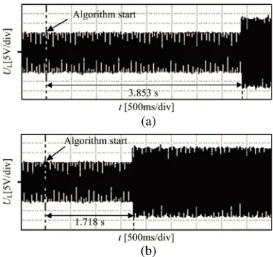
Figure 12 compares the variation of measured voltage across load at the transfer distance of 10 cm when using the traditional PSO algorithm and the proposed optimized PSO algorithm.
As shown in Fig. 12, the output voltage of the two MCR-WPT systems is 14 V at the optimal
(a)
(b)
frequency of 10.11 MHz which is larger than that using the fixed resonant frequency. Compared with the traditional PSO algorithm where the time searching for the optimal frequency is 3.853 s, the convergence of the proposed PSO algorithm is faster with the time-consuming only 1.718 s.
6. CONCLUSION
To address the problem of low transfer efficiency in the over-coupled region of the MCR-WPT system, a novel PSO algorithm based on the change of particle swarm scale is proposed in this paper. Analytical calculation, numerical simulation, and experiment have been conducted. Five types of optimizing process with different regulation parameters n are compared in the proposed algorithm. It has been found that Type 2 with n = 3 is the best alternative in all types of optimizing process. Compared with the system operating at a fixed frequency, the transfer efficiency for the system using the proposed optimized PSO algorithm is more uniform in the over-coupled region with a value generally higher than 85%. Besides, the time searching for the optimal frequency is shorter when using the proposed PSO algorithm. Therefore, the MCR-WPT system with the novel PSO algorithm is effective in improving the performance of wireless power transfer.
ACKNOWLEDGMENT
This work was supported by the Key Science and Technology Project of Henan Province of China under Grant No. 182102210080 and the Foundation for University Key Young Teacher by Henan Province of China under Grant No. 2017GGJS040.
REFERENCES
1. Lee, G., B. H. Waters, Y. G. Shin, J. R. Smith, and W. S. Park, “A reconfigurable resonant coil for range adaptation wireless power transfer,” IEEE Trans. Microw. Theory Tech., Vol. 64, No. 2, 624–632, 2016.
2. Liu, X. C. and, G. F. Wang, “A novel wireless power transfer system with double intermediate resonant coils,”IEEE Trans. Ind. Electron., Vol. 63, No. 4, 2174–2180, 2016.
3. Sample, A., D. Meyer, and J. Smith, “Analysis, experimental results, and range adaptation of magnetically coupled resonators for wireless power transfer,”IEEE Trans. Ind. Electron., Vol. 58, No. 2, 544–554, 2011.
4. Fu, M., T. Zhang, C. Ma, and X. Zhu, “Efficiency and optimal loads analysis for multiple-receiver wireless power transfer systems,” IEEE Trans. Microw. Theory Techn., Vol. 63, No. 3, 801–812, 2015.
5. Na, K., H. Jang, H. Ma, and F. Bien, “Tracking optimal efficiency of magnetic resonance wireless power transfer system for biomedical capsule endoscopy,” IEEE Trans. Microw. Theory Tech., Vol. 63, No. 1, 295–304, 2015.
6. Mi, C. C., G. Buja, Y. C. Su, and C. T. Rim, “Modern advances in wireless power transfer systems for roadway powered electric vehicles,” IEEE Trans. Ind. Electron., Vol. 63, No. 10, 6533–6545, 2016.
7. Talla, V. and J. Smith, “An experimental technique for design of practical wireless power transfer systems,”IEEE Int. Circuits Syst. Symp., 2041–2044, 2014.
8. Johari, R., J. V. Krogmeier, and D. J. Love, “Analysis and practical considerations in implementing multiple transmitters for wireless power transfer via coupled magnetic resonance,” IEEE Trans. Ind. Electron., Vol. 64, No. 4, 1774–1783, 2014.
10. Lyu, Y. L., F. Y. Meng, G. H. Yang, B. J. Che, Q. Wu, L. Sun, D. Erni, and J. L.-W. Lee, “A method of using nonidentical resonant coils for frequency splitting elimination in wireless power transfer,”IEEE Trans. Power Electron., Vol. 30, No. 11, 6097–6107, 2015.
11. Zhang, Y. M. and Z. M. Zhao, “Frequency splitting analysis of two-coil resonant wireless power transfer,”IEEE Ant. Wireless Propag. Lett., Vol. 13, No. 4, 400–402, 2014.
12. Zhang, Y. M., Z. M. Zhao, and K. Chen, “Frequency splitting analysis of four-coil resonant wireless power transfer,”IEEE Trans. Ind. Appl., Vol. 50, No. 4, 2436–2445, 2014.
13. Lan, J., H. Tang, and G. Xin, “Frequency splitting analysis of wireless power transfer system based on T-type transformer model,” Electron. Electrical Eng., Vol. 19, No. 10, 109–113, 2013.
14. Sample, A. P., D. A. Meyer, and J. R. Smith, “Analysis, experimental results, and range adaptation of magnetically coupled resonators for wireless power transfer,”IEEE Trans. Ind. Electron., Vol. 58, No. 2, 544–554, 2011.
15. Kim, J., D. H. Kim, and Y. J. Park, “Analysis of capacitive impedance matching networks for simultaneous wireless power transfer to multiple devices,” IEEE Trans. Ind. Electron., Vol. 62, No. 5, 2807–2813, 2015.
16. Fu, M., H. Yin, X. Zhu, and C. Ma, “Analysis and tracking of optimal load in wireless power transfer systems,”IEEE Trans. Power Electron., Vol. 30, No. 7, 3952–3963, 2015.
17. Vasilev, I., J. Lindstrand, V. Plicanic, and H. Sjoland, “Experimental investigation of adaptive impedance matching for a MIMO terminal with CMOS-SOI tuners,” IEEE Trans. Micro. Theory Tech., Vol. 64, No. 5, 1622–1622, 2016.
18. Koh, K. E., T. C. Beh, T. Imura, and Y. Hori, “Impedance matching and power division using impedance inverter for wireless power transfer via magnetic resonant coupling,” IEEE Trans. Ind. App., Vol. 50, No. 3, 2061–2070, 2014.
19. Heebl, J. D., E. M. Thomas, and R. P. Pennoand A. Grbic, “Comprehensive analysis and measurement of frequency-tuned and impedance-tuned wireless non-radiative power-transfer systems,”IEEE Antennas Propag. Mag., Vol. 56, No. 4, 44–60, 2014.
20. Lee, W. S., W. I. Son, K. S. Oh, and J. W. Yu, “Contactless energy transfer systems using antiparallel resonant loops,” IEEE Trans. Ind. Electron., Vol. 61, No. 1, 350–359, 2013.
21. Li, H., H. Zhang, C. Zhang, P. Li, and R. Cropp, “A novel unsupervised levy flight particle swarm optimization (ULPSO) method for multispectral remote-sensing image classification,”International Journal of Remote Sensing, Vol. 38, No. 23, 6970–6992, 2017.
22. Jabri, I., A. Bouallegue, and F. Ghodbane“Misalignment controller in wireless battery charger for electric vehicle based on MPPT method and metaheuristic algorithm,” Wireless Netw., Vol. 10, 1–22, 2017.
23. Schuetz, M., A. Georgiadis, A. Collado, and G Fischer“A particle swarm optimizer for tuning a software-defined, highly configurable wireless power transfer platform,” Wireless Power Transfer Conference, 1–24, 2015.
24. Hu, H. and S. V. Georgakopoulos, “Multiband and broadband wireless power transfer systems using the conformal strongly coupled magnetic resonance method,” IEEE Trans. Ind. Electron., Vol. 64, No. 5, 3595–3607, 2017.