Vol. 4, Issue 7, July 2015
Open Loop Analysis of H-Bridge Type Flying
Capacitor Multilevel Inverter
S.Devaraj
1, Dr.Anitha G S
2PG Student [EPE] , Dept. of Electrical and Electronics Engineering, RV College of Engineering, Bengaluru, India
Associate Professor, Dept. of Electrical and Electronics Engineering, RV College of Engineering, Bengaluru, India
ABSTRACT: Multilevel inverters play a key role in the areas of medium and high voltage applications. Among the three main commercial multilevel topologies used, the flying capacitor multilevel inverter(FCMLI) has an advantage with respect to voltage redundancies. This work proposes a switching pattern to improve the performance of chosen H-bridge type FCMLI over conventional FCMLI. The modulation technique employed in this work is Phase Opposition Disposition PWM(PODPWM). The performance of proposed H-bridge type FCMLI is verified through MATLAB-Simulink based simulation. It has been observed that the harmonic content is low in chosen FCMLI compared to conventional FCMLI.
KEYWORDS: Flying Capacitor Multilevel Inverter, Multilevel inverter, Phase Opposition Disposition –Pulse Width Modulation, Sinusoidal Pulse Width Modulation, Total Harmonic Distortion
INTRODUCTION
The Multilevel voltage source inverter topologies are the best suited for medium and high voltage applications in the industries
.
Mainly, there are three topologies of multilevel voltage source inverters [1–5]: neutral point clamped (NPC) ,flying capacitor (FC) and cascaded H-bridge (CHB). The flying capacitor topology[6] allows the conventional inverter to produce higher output voltages by using standard low-voltage switches available in the market, controlling the real and reactive power flow easily.For the modulation of multilevel inverters, carrier-based modulation techniques are usually employed. Carrier-based modulation techniques are mainly divided into two types [1,2]: phase-shifted carrier pulse width modulation (PSC-PWM) and level-shifted carrier PWM (LSC-(PSC-PWM). LSC-PWM, which is also called sub-harmonic PWM (SH-(PSC-PWM), can be categorized into the following three subgroups based on the phase disposition of the carriers: phase disposition (PD), phase opposite disposition (POD) and alternative POD[7,8]. All of these subgroups vary in the way the carriers are displaced.. The PSC-PWM is normally used for CHB inverters .The Total Harmonic Distortion(THD) of output current with the LSC-PWM is slightly better than that of the PSC-PWM, especially under low-modulation index (MI) regions. On the other hand, LSC-PWM methods are generally applied to the FC and NPC inverters, which are based on amplitude shifts between carriers. POD PWM technique has been used in this work.
MULTILEVELINVERTER
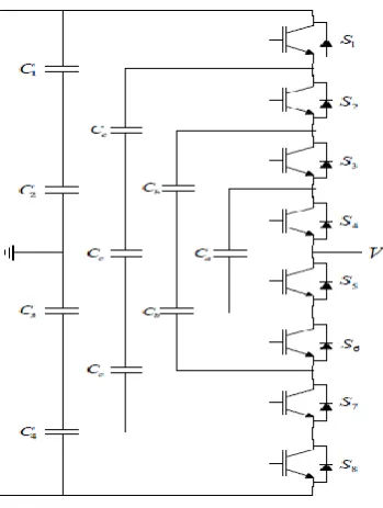
Figure 1 shows a conventional single phase five level FCMLI. One among the main benefits of FCMLI compared to NPC topology is that single capacitor substitutes two diodes which consequences in simplification of the circuit and reduction of overall losses. FCMLI provides enhanced voltage balancing across the clamping capacitors. To produce „n‟ levels of output voltage, FCMLI requires (n-1)*(n-2)/2 number of clamping capacitors per phase leg and (n-1) main dc bus capacitors. So, a conventional single phase five level FCMLI consists of 6 clamping capacitors and 4 dc bus capacitors.
Vol. 4, Issue 7, July 2015
Fig 1.Conventional single phase five level FCMLI
The chosen H-bridge type FCMLI is shown in fig 2 . In this paper, a single phase five level FCMLI uses a switching scheme in such a manner that the number of clamping capacitors is compact. We can note from figures 1 and 2 that the number of clamping capacitors is reduced to 2 from 6, which lessens the size, space and cost of the multilevel inverter. This topology assures low total harmonic distortion(THD). The table 1 shows the comparison of components used in conventional and chosen FCMLI.
Vol. 4, Issue 7, July 2015
Table-1 Comparison : Conventional and Chosen FCMLIs
Component Conventional FCMLI
Chosen FCMLI Main power
Devices 8 8
DC bus capacitors 4 2
Clamping capacitors
6 2
Number of legs 1 2
III.PHASE OPPOSITION DISPOSITION PWM TECHNIQUE
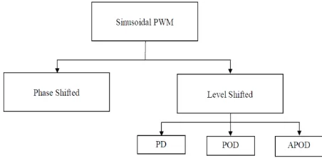
Fig 3 shows the classification of sinusoidal PWM, the sinusoidal PWM is classfied into phase-shifted PWM and level-shifted PWM. Level level-shifted PWM can be categorized into three sub-groups namely Phase Disposition PWM(PD PWM),Phase Opposition Disposition PWM(POD PWM) and Alternative Phase Opposition Disposition PWM(APOD PWM) . POD PWM technique has been employed in this work.
Fig 3. Classification of sinusoidal PWM technique
POD PWM:
In five level inverter, four carrier signals are used and the following points explain about POD PWM.
Vol. 4, Issue 7, July 2015
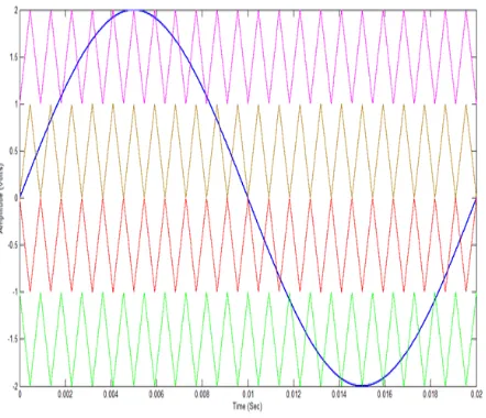
Fig 4 shows the POD-PWM generation pattern for the selected flying capacitor multilevel inverter where four triangular carrier signals and a sinusoidal reference signal. Based on the comparison, we get the resultant pulses. Those pulses are given to the gating signal of the switching devices. As there are complementary switches in the circuit, if one pulse is given to a switch, negative of that pulse is given to its complementary switch.
. Fig 5. The carrier signals and the modulating signals
The switching diagram is shown in fig 5. The sinusoidal reference signal and the triangular carrier signal is shown. As we can observe from the figure, the amplitude of each triangular signal is one-fourth of that of the sinusoidal signal. Here , peak-peak amplitude of the sinusoidal signal is taken as 2, so the amplitude of each triangular signal is 0.5. The comparison is done between the reference signal and the carrier signals and a pulse is generated if sinusoidal signal is greater than carrier signal.
Table 2. Simulation parameter values
Parameter Value
DC input voltage 220V
Flying capacitor 220uF
Carrier frequency 1100Hz
Load 100 Ohms
IV. OPEN LOOP SIMULATION
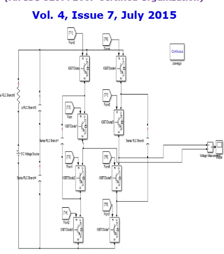
Using MATLAB , the open loop circuit has been modelled and simulated in Simulink. The values of the component parameters used in the simulation are as shown in table 2. The simulation diagram of the open loop Simulink model is shown in
Vol. 4, Issue 7, July 2015
Fig 6. Open loop Simulink model
The simulation results are shown in the following figures:
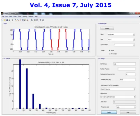
Fig 7 shows the output voltage of the open-loop conventional flying capacitor multilevel inverter using POD-PWM. We can observe from the figure that the voltage waveform is much distorted from the desired sinusoidal waveform. Hence, we use a H-bridge type FCMLI to reduce the harmonic content.
Fig 7. Output voltage of conventional CCMLI
Vol. 4, Issue 7, July 2015
Fig 8. THD of output voltage of conventional FCMLI
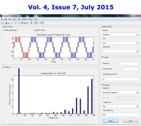
Fig 9 shows the output voltage waveform of the selected H-bridge type FCMLI. When compared to the voltage waveform of the conventional FCMLI, this waveform looks better sinusoidal and the harmonic content is reduced .
Fig 9. Output voltage of chosen H-bridge type FCMLI
Vol. 4, Issue 7, July 2015
Fig 10. THD of output voltage of of chosen H-bridge type FCMLI
From the figures (7) through (10), it can be observed that we get a better quality voltage waveform for H-bridge type FCMLI compared to conventional FCMLI. The Total Harmonic Distortion for the modified multilevel inverter system is 26.9% compared to 32% for conventional FCMLI.
V.FUTUREWORK
Using MATLAB Simulink tool, the closed loop control model of chosen FCMLI will be attained. The control loop will be simulated using Proportional Integral Derivative (POD) controller. Using the controller values , a code will be developed which will be embedded in the PIC controller in the hardware implementation.
REFERENCES
[1] Priyan, S.S., Ramani, K.: “Implementation of closed loop system for flying capacitor multilevel inverter with stand-alone photovoltaic input”. Proc. IEEE 2013 Int. Conf. Power, Energy and Control (ICPEC), February 2013, pp. 281–286
[2] Malinowski, M., Gopakumar, K., Rodriguez, J., Pérez, M.A : “A survey on cascaded multilevel inverters”, IEEE Trans. Ind. Electron., 2010, 57, (7), pp. 2197–2206
[3] Mahesh kumar.N., Mahesh kumar.V., Divya,.M.E.M.: “The new topology in flying capacitor multilevel inverter”. Proc. IEEE 2013 Computer Communication and Informatics (ICCCI), January 2013, pp. 1–6
[4] McGrath, B.P., Holmes, D.G.: “Multicarrier PWM strategies for multilevel inverters”, IEEE Trans. Ind. Electron., 2002, 49, (4), pp. 858–867 [5] Sneineh, A.A., Wang, M.-y., Tian, K.: “A new topology of capacitor-clamped cascaded multilevel converters”. Proc. IEEE 2006,Power
Electronics and Motion Control Conf., August 2006, pp. 1–5
[6] Lai, J.-S., Peng, F.Z.: “Multilevel converters – a new breed of power converters”. Proc. IEEE 1995 Industry Applications Conf., October 1995, pp. 2348–2356
[7] Palanivel, P., Dash, S.S.: “Analysis of THD and output voltage performance for cascaded multilevel inverter using carrier pulse width modulation techniques”, IET Power Electron., 2011, 4, (8), pp. 951–958