Rectangular Patch Antenna Array for
Wireless Application
Jhaman Das
M.Tech Student
Al-falah School of Engineering & Technology,Dhauj , Faridabad (Haryana), India Email: [email protected]
Tzeem Ahmed khan
Asst. Prof.
Al-falah School of Engineering & Technology,Dhauj , Faridabad (Haryana), India
Manoj Kumar Pal
Bharat Sanchar Nigam Ltd. Meerut, India Email: [email protected]
Abstract :
This paper presents design and implementation of Linear antenna array of size 1x4.The elemental base shape antenna utilizes rectangular patch feeded through microstrip feed to achieve higher gain, highly directional beam and also to counteract the effect of fading while signal propagates through various corrupted environments. . It is demonstrated that the proposed antenna works at 2.4 Ghz frequency suitable for WLAN application. The antenna is microstrip line feeded and is simulated on IE3D Zeland software. Performance parameter evaluated are also good, such as it has directivity upto 13.5 dBi Gain of about 5 dBi and Efficiency upto 80% with satisfactory radiation characteristics. The computer simulation results shows that the antenna having good impedance bandwidth (VSWR ≤2 & S11< -10 dBi) at the resonant frequency and measured results
matches with high degree of accuracy with simulated results.
Keywords –
M
icrostrip patch, Array optimization. WLAN, Interelement spacing , IE3D ,VNA.1. Introduction
The rapid development of various wireless communication systems has sparked the demand for compact microstrip antennas with high gain and directional properties to suit many wireless applications such as S-band or for 3rd generation mobile application for higher data rate transfer and longer range to provide quality services to the users. For current mobile communication, the diversity scheme has already been implemented to mitigate the fading effects of multipath scenario [1-2]. Microstrip patch antenna has advantages such as low profile, conformal, light weight, simple realization process and low manufacturing cost. However, the general microstrip patch antennas have some disadvantages such as narrow bandwidth of about (2% - 5%) and less gain etc [3-4]. However in array applications a microstrip line feed may often be more appropriate and a large no of research papers are available on the same [5-8]. Since the bandwidth of the antenna increases with an increase in the substrate thickness h or with a decrease in the dielectric constant εr. However, there is a practical limit on
increasing the h, and if increased beyond 0.1λ0, surface-wave propagation takes place, resulting in degradation in antenna performance [9].
An aperture coupled antenna has special advantages because of its simple structure, such as wider bandwidth, less conductor loss, and better isolation between the radiating element and feed network .It can also provide the merits of low profile, low cost, small size, easier integration with other circuits and conformability to a shaped surface. The placement of slots can may be coupled basis or tech of cross shaped. [10–12].
This article describes the design, analysis and simulation of linear array made up with elemental basic shape of dual layered structure having slot cut in intermediate ground plane surface and rectangular patch on upper patch while microstrip feed line on bottom surface as shown in fig. 2. We focused on the designing of antenna aspect of array system having two and four element microstrip patch configuration. The proposed single element and multi elements patch antenna array operates for recent wireless communication. Performance simulations of the antenna were carried out with IE3D software, which is based on the method of moments [13].
(2)
Using equation (2), to improved the value of L,
(3)
Where ∆ L i.e change in L due to fringing effect and effective dielectric constant εeff can be given as
(4)
= ( (5)
2.2. Designing of Linear Array
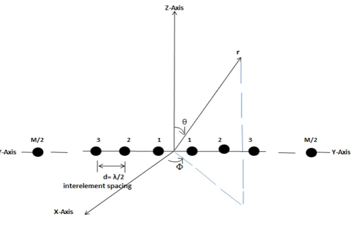
Following the design of the individual rectangular patch antenna, a linear array of two and four microstrip patches with interelement spacing of λ/2 (half wavelength), where λ is 125 mm (based on the resonance frequency of 2.4 GHz), is designed. Since the number of array elements affects the beamwidth of a radiation pattern. That is, when more elements are used in an array (larger size array) ,the narrower is the main beam. The array factor of a linear array of M (even) identical elements with uniform spacing positioned symmetrically along the y-axis, as shown in fig. 1, can be written as
(AF)M = W1e+j(1/2)ψ1+ W2e+j(3/2)ψ2+ ··· + WM/2e+j[(M−1)/2]ψM/2 + W1e−j(1/2)ψ1+ W2e−j(3/2)ψ2+ ··· +
WM/2e−j[(M−1)/2]ψM/2
(6)
Simplifying and normalizing equation no.6, the array factor for an even number of elements with uniform spacing along the y-axis reduces to
Fig. 1 Linear Array having its elements along Y-axis
In equation nos.7 and 8, Wn and
β
n represent, respectively, the amplitude and phase excitations of the individual elements..3 PROPOSED ANTENNA GEOMETRY
Before designing the antenna, the first step is to consider the specification of the base shape antenna on the basis of its application. The base shape has to be designed by considering resonance frequency as 2.4 Ghz for wireless application.
Table 1.0: Single Patch Antenna Design Specifications
Frequency 2.4 GHz
Substrate FR4
Dielectric Constant, (εr) 4.7
Loss Tangent 0.019
Substrate Height 1.6 mm
Conductor Thickness 35.0 um
Further the design of antenna as single patch is provided below along with its array application using four basic patches is also designed in the similar way. The basic patch have a patch of dimension 36.27 x27.9 mm on above substrate and the bottom layer of substrate have the finite ground.
(b)
Fig.2 Proposed Antenna geometry (a) Antenna with designed dimensions (b) Side view of proposed antenna structure
(b)
Fig.3 Designed Linear Antenna Array geometries having (a) Two element (b) Four elements
4. Simulated Results
The performance of this antenna was simulated and optimized by “IE3D” 14 version of Zeland. This was used to calculate the return loss, impedance bandwidth and radiation pattern alongwith directivity, gain and antenna efficiency etc for performance analysis of the antenna. In this regard the primary step is to measure the Return Loss parameter i.e (S11) and VSWR for proposed antenna as given below in fig. nos. 4 & 5.
Fig.4 Simulated return Loss curve for the array antenna geometry having Four element.
Fig.5 Simulated VSWR curve for the array antenna geometry having Four element.
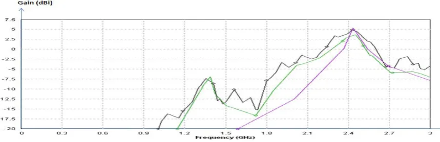
Other important parameters such as Directivity, Gain and Antenna efficiency are also evaluated /simulated for antenna. From fig 6.0, the curve is drawn in between Directivity and frequency and it is meaningful that value of directivity increases from 6 dBi to 13 dBi while approaching from single patch antenna to its array having four basic patches.
Fig.6 Comparison of Directivity for Single patch (Green ), Dual patch array (purple ), Array using Four basic patches (Black )
Fig. 8 Comparison of Antenna Efficiency for Single patch (Green ), Dual patch array (Purple ), Array using Four basic patches (Black )
The antenna parameters shown above are also discussed in tabular form for quntative analysis point of view for all the designed geometries is given below in table 2 for ready reference for the same.
Table-2.0 Antenna parameter comparison for Microstrip Feed Rectangular Patch Antenna
Antenna Type Resonance Freq.(Ghz)
Directivity (dBi)
Gain (dBi)
Antenna Efficiency (in %)
Basic Patch 2.4 7.5 5 75%
Array using two
basic patch 2.4 12 5 25%
Array using four
basic patch 2.4 14 5 15%
The table compares the values of Return Loss along-with directivity,gain and antenna efficiency for review of antenna performance parameters.
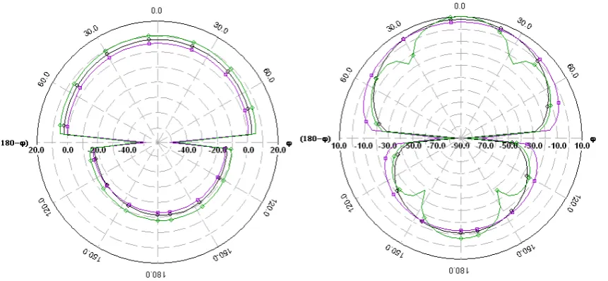
Apart from above shown parameters the proposed antenna has the promising radiation patterns in 2-dimensional plane in form of polar plots. The polar plots for E-plane (Φ = 00 deg. ) and H-plane (Φ = 90o deg.)- given below in fig. 9(a) and 9 (b) in which the curve drawn in purple colour is for basic elemental patch design and curves drawn in black and green colour are for array having two and four elements respectively.
Fig. 10 Prototype fabricated antenna under testing
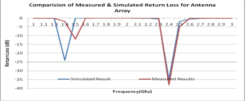
Fabricated antenna on Glass Epoxy material analyzed with Network analyzer (VNA) for finding out Return Loss (S 11 ) parameter in dB as shown in the Fig. 10 .
Fig.11 Comparison in between in b/w measured and simulated return loss curves for fabricated antenna
References
[1] K. Fujimoto and J.R. James, Mobile antenna system handbook, 2nd edition, Artech House Inc., 2001
[2] Gonca CAKIR,Levent SEVGI, “ Design, Simulation and Tests of a Low-cost Microstrip Patch Antenna Arrays for the Wireless Communication”, Turk J Elec. Engin, Vol. 13. No. 1 2005.
[3] C. A. Balanis, Antenna Theory - Analysis and Design, 3rd edition, Wiley, 2006 [4] R Garg, P. Bhatia,I.J. Bahl, Microstrip Antenna,DesignHandbook, Artech House, 2000
[5] Ely Levine, Gabi Malamud, David Treves “AStudy of Microstrip Array Antennas with theFeed Network” IEEE Transactions on Antennas and Propagation, Vol. 37, No.4,1989.
[6] Styeskal, H. and J. S. Herd, “Mutual coupling compensation in small array antennas,” IEEE Trans. AP, Vol. 38, No. 12, 1971–1975, Dec. 1990.
[7] Gijo Augustin, P. C. Bybi, V. P. Sarin, P. Mohanan, C. K. Aanandan, and K. Vasudevan, “A Compact Dual-Band Planar Antenna for DCS-1900/PCS/PHS, WCDMA/IMT-2000,and WLAN Applications”, IEEE Antennas WirelessPropag. Lett., vol. 7, pp. 108-111,2008 [8] Mailoux, R. J. and J. F. Mcilvenna, 1981. Microstriparray technology. IEEE Trans. Antennas and Propagation, AP: 29
[9] X. Gang,“On the resonant frequencies of microstrip antennas,”IEEE Trans Antennas Propagation, pp. 245-247, Feb. 1989. [10] D.M.Pozar,"Microstrip antenna aperture coupled to a microstrip line,” Electronic Lett., vol.21 no.2. pp [49-50],Jan. 1985
[11] Peter L. Sullivan and Daniel H. Schaubert, “Analysis of an aperture coupled microstrip antenna,” IEEE Trans. Antennas and Propagation, vol. AP-34, No.8, August 1986
[12] Ian Hua Yang and Lotfollah Shafai, “Characteristics of aperture coupled microstrip antennas with various radiating patches and coupling apertures,” IEEE Trans. Antennas and Propagation,vol. AP-43, No.1,January 1995.
[13] IE3D, Zeland Software. IE3D User’s Manual Release 9. Zeland Software Inc. Available online: http://www.zeland.com
[14] Y. Bah¸ ceci and T. M. Duman, “Combined Turbo Coding and Unitary Space-Time Modu-lation,” IEEE Trans. Commun., Vol. 50, No. 8, pp. 1244–1249, Aug. 2002.
[15] Y. Bah¸ ceci, “Trellis- and Turbo-Coded Modulation for Multiple Antennas Over Fading Channels,” MS Thesis, Arizona State University, Aug. 2001.
![Ring transformation of 1,3,4 oxadiazoles into novel [1,2,4]triazolo[3,4 b][1,3,4]thiadiazines and their antimicrobial and antioxidant properties](data:image/gif;base64,R0lGODlhAQABAIAAAP///wAAACH5BAEAAAAALAAAAAABAAEAAAICRAEAOw==)