e-ISSN: 2278-067X, p-ISSN: 2278-800X, www.ijerd.com
Volume 11, Issue 03 (March 2015), PP.27-33
Performance Optimization of Tie rod using FEA
Shripad Mungi
1, Prof. Ravindra Navthar
2M.E. Student, Dept. of Mechanical Engineering, PDVVP College of Engineering, Ahmednagar, India Savitribai Phule Pune University
Associate Professor, Dept. of Mechanical Engineering, PDVVP College of Engineering, Ahmednagar, India Savitribai Phule Pune University
Abstract:- Structural performance of any mechanical component is measured basically in terms of its natural frequency, deformation, stiffness, maximum stress level, fatigue life etc. In case of vehicle suspension system; however tie rod is mainly under compressive and fluctuating forces encounter from steering and bumping of vehicle. When steering acts to turn the vehicle, tie rod comes under compressive load. And when vehicle running on rough road condition, fluctuating forces.
When we design the tie rod we need to know the design space available. The prime objective is minimize weight and cost. In order to achieve these targets we have optimize the parameters that affects the structural performance of Tie rod. This paper emphasizes on optimistic way of designing the tie rod that ultimately yields the effective and efficient performance of Tie rod.
Keywords:- FEA, Modal FEA, Natural frequency, stiffness.
I.
INTRODUCTION
A tie rod is an important member in vehicle suspension system. It performs an important task of transferring the motion from steering system to suspension system. In a car‟s steering wheel is connected to the steering gear steering wheel turn the wheels. The steering gear is connected to the wheels via the tie rod ends. The job of the tie rod end is to ensure the wheels are aligned. It provides the adjustment for wheel alignment that keeps the tires from wearing out on the inner and outer edges. If they wear out, the wheels will lose alignment and you may find that the tires and steering wheels are shaking when you drive the car.
To evaluate the structural performance of tie rod, we need to consider the loads coming on tie rod. From various studies and practical observations, it is found that tie rod is primarily encounter under compressive loads and hence fails in buckling. Moreover due to suspension components fluctuating loads are also coming on tie rod due to random loads coming on suspension of vehicle.
A. Role of tie rod in suspension system
Failure of tie rod may occurs in terms of plastic (permanent) deformation or a fatigue failure. And it may cause the running vehicle in an unstable condition which may cause an accident. So it‟s important to validate the tie rod in every aspect of structural loading. The load coming on tie rod is mostly compressive. The efforts required where car is moving are comparatively less with stationary car. The working strength of the tie rod is that of the product of the allowable working stress and the minimum cross-sectional area.
Figure2: Location of tie rod in suspension system
Rods are often made thicker at the ends and to keep its strength high at tie rod ends. It is advisable that steering and suspension systems are checked regularly, at least once a year along with a complete wheel alignment. A worn tie rod can cause loss of grip of vehicle, drifting, erratic steering and also major tire wear. If a tie rod is replaced, then a wheel alignment will also be required. Because tie rod replacement will disturb the alignment setting. As the ratio of its length to the radius of gyration of its cross section is normally quite large, it would likely buckle under the action of compressive forces.
II.
PROBLEM
DEFINITION
Initially the theoretical study of Tie rod is done. The main task in this study is to find the critical buckling load for the existing design. Observe the deformation and stresses induced in the Tie rod. Set up the benchmark for the proposed design. Try to evaluate the possibility with different material combinations for optimized design. Target is to minimize the weight keeping the critical buckling load constant. The stress targets are also need to be achieved.
A. Aim and Objective
An objective of this project is to do the performance evaluation of an existing tie rod. This is done in terms of displacement, stress, and strain analysis. Enlist the parameters affecting the performance of tie rod under compressive loading. Evaluate the sensitivity of structure against different input parameters. Decide the optimization scope for weight reduction. Construct the design of new optimized model.
B. Linear buckling analysis:
In linear static analysis, a structure is normally considered to be in a state of stable equilibrium. As the applied load is removed, the structure is assumed to return to its original position. However, under certain combinations of loadings, the structure may become unstable. When this loading is reached, the structure continues to deflect without an increase in the magnitude of the loading. In this case, the structure has actually buckled or has become unstable; hence, the term “instability” is often used interchangeably with the term “buckling.”
C. Parameters affecting the critical buckling load of a structure.
We know that, critical buckling load is given by Pcr= (π^2 EI)/ (4L^2)
Here, π is constant.
E, I and L are variables which can control the critical load value. In order to get the higher Pcr value
„E‟ and „I‟ must be higher „L‟ should lower
Now, I = π [Do^4 - Di^4] / 64
So the value D value affects in quadratic.
Hence for design against the buckling loads, one should select the material having maximum E value, keeping length as minimum as possible, select maximum outer diameter in order to maximize the inertia value and lower the L/D ratio.
In case of tie rod we have carried out many such combinations / iterations that will give the maximum value of critical load with lowest invest of mass (optimized solution).
D. Sensitivity analysis:
In order to study the buckling performance of structure, each parameter affecting the buckling performance is studied. The inertia of structure is plotted for various diameters incrementally. The critical buckling load is also calculated for these diameters. When both the graphs plotted together, it is interesting to observe that, for small interesting to observe that, for small increase in inertia there is significant rise in the critical load. This signifies that, inertia is very sensitive to the critical buckling load. Hence it can be concluded that the structure should be selected such that it has maximum inertia value.
Further there can be other parameters also which are sensitive to the buckling performace of a strucutre. For circular cross sections inertial is quadratically dependent on the outer diameter. Hence if we change the outer diameter by small amount; there is significant change in the inertia value of structure.
Moreover the young‟s modulus of material is directly proportional to the critical load. Hence it is recommended to prefer the material having high value of young‟s modulus.
Figure 3: Critical buckling load (Pcr) Vs Inertia (I)
III.
PERFORMANCE
EVALUATION
OF
TIE
ROD
USING
FEA
Nastran Linear Statics Analysis User‟s Guide give the fundamental of linear buckling analysis. Finite element approach including the effect of the differential stiffness to the linear stiffness matrix. The differential stiffness results from including the higher-order terms of the strain-displacement relationships. Eigenvalue extraction method used in linear buckling are Inverse power, Enhanced inverse power, Lanczos method. Assumptions and limitations of linear buckling analysis need to be consider before analysis.
A. Existing and Proposed Tie rod FE analysis.
Table 1: Structural details of Tie rod
Sr. No. Quantity Unit Existing design Proposed design
1 Outer diameter mm 15.9 18.5
2 Inner diameter mm 10.6 15.5
3 Length mm 345 345
4 Thickness mm 2.65 1.5
5 Mass kg 0.503 0.422
6 Modulus of Elasticity N/mm2 210000 210000
B. Extraction of Natural frequency and mode shape:
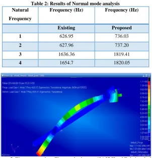
Table 2: Results of Normal mode analysis Natural
Frequency
Frequency (Hz) Frequency (Hz)
Existing Proposed
1 626.95 736.03
2 627.96 737.20
3 1636.36 1819.41
4 1654.7 1820.05
Figure 5. Eigenvector plot - First mode shape – 626.37 Hz of Existing design
C. Critical buckling load evaluation
Theoretical calculations (approximate) for critical buckling load Linear buckling of Euler column.
For clamped-free boundary conditions the critical load is: Pcr = (pi**2) EI/ (4(L**2))
Where, E=10.5E6, I=8.333-5, L=320 Pcr = 13158.0
D. Calculating critical buckling load with SOL 105
From f06 file we receive the first eigenvalue as shown below.
Here the Eigenvalue = 1.608350E+02 Applied load = 100 N
Critical buckling load (Pcr) = Eigenvalue * Applied load = 16083.5 N
IV.
RESULT SUMMARY AND INTERPRETATIONA. Summary of results
Result Table 5: - Buckling load – Theoretical (Approx.)
Sr. No. Quantity Unit Existing design Proposed design
1 Critical buckling load N 13158.27 14776.32
Result Table 6: - Linear buckling analysis – SOL 105
Sr. No. Quantity Unit Existing design Proposed design
1 Critical buckling load N 16083.01 17707.04
B. Result interpretation
We have carried out the theoretical calculations as well as the FEA linear buckling analysis for tie rod. From the above result tables, we can observe that, the critical buckling load calculated from the theoretical method is comparatively lower than the linear and non-linear buckling analysis. This is due to the fact that, in theoretical calculations the tie rod is assumed thoroughly hollow and of uniform section. The variations in cross sections cannot be accounted in theoretical procedure. This is the limitation of theoretical procedure and the reason why we do the finite element analysis. As the FEA can take care of all these issues which analytical method cannot consider.
From linear buckling analysis the critical buckling load value obtain is around 16kN for existing design and around 17.7kN in proposed design. The rise in the critical buckling load is attributed to the rise in inertia value of proposed design.
Looking at the displacement plot of the first natural frequency of both existing and proposed design; we can observe that the location of maximum displacement is at the centre of tie rod.
0 SUBCASE 2
R E A L E I G E N V A L U E S
V.
CONCLUSIONS
A research starts with study of various types of sections proposed for design of tie rod. An objective of this research is a weight optimization. Here we are proposing the optimized design of Tie rod that has a minimum weight and maximum critical buckling load carrying capacity.
From results of normal mode analysis, it is seen that the natural frequency of existing design is 626 Hz and proposed design is 736 Hz. So there is ~ 18% rise in natural frequency of proposed design. Further the second and onwards the frequencies of proposed design are increased compared to existing design. So overall the dynamic performance of tie rod is being improved.
The weight of existing tie rod is ~ 0.498 Kg and proposed design is ~ 0.421 Kg. So there is approximately around 14% weight reduction is achieved. Apart from weight savings, it is interesting to note that the critical buckling load of existing design is 16.08 kN against critical buckling load of 17.7 kN of proposed design. Hence there is 10% rise in load carrying capacity of tie rod, which is quiet significant.
VI.
FUTURE
SCOPE
1. In this research the tie rod has been evaluated under critical buckling load conditions. A linear buckling analysis have been carried out successfully. As we know the tie rod is a suspension component. Hence it is continuously exposed to fatigue loading condition. Hence the fatigue life estimation under full vehicle condition is recommended to be performed.
2. One can initially decide the expected fatigue life of tie rod component. Based on targeted life, an optimization can be performed to minimize the weight keeping the performance unaltered. This can be done with advanced tools line solver embedded fatigue.
3. Material having higher modulus of elasticity are suitable under buckling load conditions. Hence the composites or high carbon alloy steels having higher E value can be implemented.
4. Circular cross sections are most suitable under fatigue loading conditions. But other shapes of cross sections can also be tried e.g. elliptical shapes.
5. Completely hollow sections can be suitable for tie rod design. But for actual OEM, with the availability of good set up and for large scale manufacturing, full hollow shaft can be manufactured. Which can further reduce the weight.
REFERENCES
[1]. Pradeep Mahadevappa Chavan1 and M Patnaik (2014) “Performance evaluation of passenger car tie rod using numerical and theoretical approach with different materials” IJRET: International Journal of Research in Engineering and Technology, Volume: 03 Issue: 08 eISSN: 2319-1163 pISSN: 2321-7308. [2]. Raghavendra K and Ravi K (2014) “Buckling analysis of tractor tie rod subjected to compressive load”
International Journal of Mechanical and Industrial Technology, Vol. 2, Issue 1, pp: (125-129).
[3]. George Campbell, Wen Ting from Ford Motor and Peyman Aghssa and Claus C. Hoff from MSC Software (1994) “Buckling and Geometric Nonlinear Analysis of a Tie Rod in MSC/NASTRAN Version 68” World Users' Conference (pp.1-15). Lake Buena Vista, FL: MSC Software Corporation, (Acrobat 630KB) #1594
[4]. Manik A. Patil1 et al (2013) “FEA of Tie rod of steering system of car” International Journal of Application or Innovation in Engineering & Management (IJAIEM), Volume 2, Issue 5, May 2013 ISSN 2319 - 4847
[5]. Brandon H. Wegge engineer Lean Enterprise, The Boeing Company, Ridley Park, PA and Lance Proctor Sr. Technical Representative, MSC Software, Chambersburg, PA (2002) “A statistical method of identifying general buckling modes on the Chinook helicopter fuselage” Worldwide Aerospace Conference & Technology Showcase, Toulouse, France.
[6]. Sang H. Lee MSC.Software Corporation (2001) 2 MacArthur Place, Santa Ana, CA 92707, “Essential Considerations for Buckling Analysis” Worldwide Aerospace Conference and Technology Showcase, Toulouse, France
[7]. Ir. J.J. Wijker, Ir. F.M. Maitimo and Ing. C.J. de Haan of Fokker Space B.V. Dep. Engineering Mechanical Engineering, P.O. Box 32070, NL-2030 DB Leiden, The Netherlands. (1999) “Modal Analysis - An Elegant Solution” 1999 MSC Aerospace Users' Conference, #5299, 19 pgs
[8]. Klaus Otto Schwarzmeier, Eng. EMBRAER - Empresa Brasileira de Aeronáutica S/A Avenida Brigadeiro Faria Lima, 2170 – Putim 12227-901 - São José dos Campos – SP BRAZIL “DIAG-2 geometric nonlinear parameters calculation for diagonal tension simulation using MSC/Nastran” 1999 MSC Aerospace Users' Conference, 5399, 14 pgs
[10]. David F Bella, Senior Development Engineer, The MacNeal-Schwendler Corporation (1995) “DMAP Alters to add differential stiffness and follower force matrices to MSC/Nastran linear solutions” MSC 1995 World Users' Conference (Acrobat 341KB) #3395
[11]. M.H.Schneider, Jr. and R.J. Feldes from McDonnell Douglas Aerospace, Huntington Beach, California J.R. Halcomb and C.C.Hoff, from MSC Software (1995) “Stability analysis of perfect and imperfect cylinders using MSC Nastran Linear and nonlinear buckling” MSC 1995 World Users' Conference #2795