University of South Carolina
Scholar Commons
Theses and Dissertations
1-1-2013
Design and Synthesis of Polymer-Based Advanced
Nanomaterials Using Raft Polymerization and
Click Reaction
Junting Li
University of South Carolina
Follow this and additional works at:https://scholarcommons.sc.edu/etd
Part of theChemistry Commons
This Open Access Dissertation is brought to you by Scholar Commons. It has been accepted for inclusion in Theses and Dissertations by an authorized administrator of Scholar Commons. For more information, please [email protected].
Recommended Citation
by
Junting Li
Bachelor of Science
East China University of Science and Technology, 2006
Master of Science
East China University of Science and Technology, 2008
Submitted in Partial Fulfillment of the Requirements
For the Degree of Doctor of Philosophy in
Chemistry and Biochemistry
College of Arts and Sciences
University of South Carolina
2013
Accepted by:
Brian C. Benicewicz, Major Professor
Chuanbing Tang, Committee Member
Thomas Vogt, Committee Member
Harry Ploehn, Committee Member
First, I would like to thank my advisor Prof. Brian Benicewicz for giving me the
opportunities to achieve this intriguing and innovative research. His support and
encouragement for me had never changed even after many times of failures in my
experiments, and his insight and profound expertise served as the best guidance
throughout my Ph.D. studies. I also want to thank all my committee members: Prof.
Chuanbing Tang, Prof. Tomas Vogt and Prof. Harry Ploehn for their useful suggestions
regarding my proposal and my Ph.D. research.
I would like to acknowledge my collaborators – Prof. Linda Shadler and Dr.
Jianing Gao at Rensselaer Polytechnic Institute, Prof. Sanat Kumar and Dr. Yuping Xie at
Columbia University for their valuable contributions and advices to this work. The
experience working with these knowledgeable and helpful people in the interdisciplinary
projects let me have a higher version of the material science and learn more extensive
beyond chemistry.
Many thanks are due to the members of Benicewicz group past and present for
their constant assistance and suggestions. In particular, I want to thank Dr. Yu Li and Dr.
Cash Brandon for being the best mentors I could have had.
Last but not least, I want to express my greatest gratitude to my parents and my
fiancée – Di Song. This achievement could not have been possible without their love,
A
BSTRACTThis research focuses on exploring new synthetic approaches to prepare
polymer-based advanced nanomaterials using highly efficient chemical tools, such as reversible
addition-fragmentation chain transfer (RAFT) polymerization and click reactions.
In the first project, novel synthetic routes to produce fullerene-based polymers
were designed. First, mono-alkynyl functionalized fullerene was prepared starting with
pristine fullerene (C60). Methyl methacrylate and 6-azido hexyl methacrylate were then
randomly copolymerized via RAFT polymerization with well-controlled molecular
weights and copolymer compositions. Finally, the two moieties were covalently
assembled into a series of well-defined side-chain fullerene polymers (SFP’s) via the
copper-catalyzed click reaction. The TGA and UV-vis analyses demonstrated consistent
and high conversions for most of the samples. Furthermore, the SEM images of these
polymers showed the formation of various supramolecular nanoparticle assemblies and
crystalline-like clusters depending on the fullerene contents and polymer chain lengths.
Additionally, “tadpole-like” fullerene polymers (TFP) were generated from bi-alkynyl
functionalized fullerene, followed by a click reaction to anchor azido-capped polymers as
“tails”. The resultant polymers behaved as surfactants to significantly improve the
solubility of graphene. The UV-vis and FT-IR spectra indicated the strong π-π stacking
interactions between the TFP’s and graphene. TEM images also displayed different
(NP’s). A critical challenge in NP functionalization has been the preparation of
polymer-grafted asymmetric (Janus) NP’s (dia. <100 nm). After multiple trials using different
protection-deprotection methods and face-blocking moieties, such as wax beads and
planar silica wafers, we designed a robust and cyclic method to synthesize such NP’s
involving a reversible click reaction and a “grafting to” strategy. A novel
mechanochemical approach was introduced into the particle interactions to selectively
achieve the protection-deprotection of NP’s, which was combined with polymer
modification of the unprotected surfaces of the NP’s via a “grafting to” approach. The
azide-functionalized larger particles could be recycled as face-blocking moieties. Using
this pathway, we prepared 15 nm silica NP’s that were partially functionalized with
poly(methyl methacrylate). Additionally, the unique self-assembly behaviors of the
resultant Janus NP’s and their interactions with isotropic NP’s were investigated in
different solvents and concentrations by TEM and AFM analyses.
The dispersion of NP’s in polymer matrices is a critical factor in determining the
properties of the resulting nanocomposites. In the last part, we studied on NP’s
modification via surface-initiated RAFT polymerization using various functional
monomers, and the dispersion of the NP’s in different polymer matrices. Kinetic studies
were investigated for each polymerization to demonstrate the controlled nature of the
polymerization on the surface of the NP’s. In addition to the homopolymers, multi-layers
of block copolymer brushes were grafted on silica NP’s by sequential RAFT
polymerizations. Moreover, “pseudo” gradient copolymer brushes were also prepared by
blocks, which was established as an easy and straightforward method to synthesize
ACKNOWLEDGEMENTS ... iii
ABSTRACT ... iv
TABLE OF CONTENTS ... vii
LIST OF TABLES ... ix
LIST OF FIGURES ...x
LIST OF SCHEMES ... xiv
CHAPTER 1:INTRODUCTION ...1
1.1Reversible Addition-fragmentation Chain Transfer Polymerization ...1
1.2 Reversible Copper-mediate Click Reaction in Polymer Chemistry ...3
1.3 Synthesis of Fullerene Polymers ...7
1.4 Surface Modification of Nanoparticles ...11
1.5 Synthesis of Janus particles ...14
1.6 Motivation and outline ...16
1.7 References ...18
CHAPTER 2:SYNTHESIS OF FULLERENE POLYMERS VIA COMBINATION OF RAFT POLYMERIZATION AND CLICK REACTION ...23
2.1Introduction ...23
2.2Experimental Section ...26
2.3 Results and Discussion ...32
2.5 References ...61
CHAPTER 3:SYNTHESIS OF POLYMER-GRAFTED JANUS NANOPARTICLES VIA COMBINATION OF REVERSIBLE CLICK REACTION AND “GRAFT TO”STRATEGIES...64
3.1Introduction ...64
3.2Experimental Section ...66
3.3 Results and Discussion ...74
3.4 Conclusions ...91
3.5 References ...91
CHAPTER 4:SURFACE-INITIATED RAFTPOLYMERIZATION ON SILICA NANOPARTICLES WITH VARIOUS FUNCTIONAL MONOMERS ...94
4.1Introduction ...94
4.2Experimental Section ...97
4.3 Results and Discussion ...102
4.4 Conclusions ...117
4.5 References ...117
CONCLUSIONS ...120
FUTURE WORK ...122
Table 2.1 RAFT polymerization of AHMA and MMA in THF ...38
Table 2.2 Click conversion efficiency and fullerene loadings calculated by TGA and UV-vis analyses. ...41
Table 4.1 Samples of block copolymer grafted NP’s consisting of HMA and GMA ...108
L
IST OFF
IGURESFigure 1.1 Guidelines for selection of the ‘Z’ group of RAFT agents (ZC(=S)SR) for
various monomers ...3
Figure 1.2 Guidelines for selection of the ‘R’ group of RAFT agents (ZC(=S)SR) for various monomers ...3
Figure 1.3 Functional group interconversion for ATRP products ...6
Figure 1.4 Reversible formation and cleavage of 1,2,3-triazole ring embedded within a poly(methyl acrylate) chain ...7
Figure 1.5 The “grafting to” and “grafting from” strategies for grafting polymers on nanoparticles ...12
Figure 1.6 Schematic representation of the synthetic routes yielding Janus particles ...14
Figure 2.1MALDI-TOF-MS spectrum of compound 1 ...34
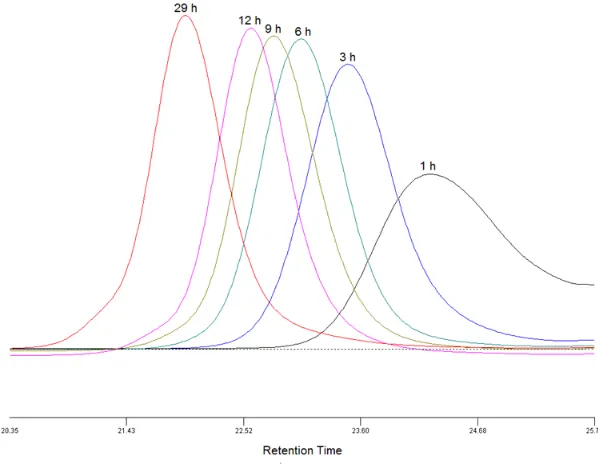
Figure 2.2 GPC traces of prepolymers for kinetics studies ...35
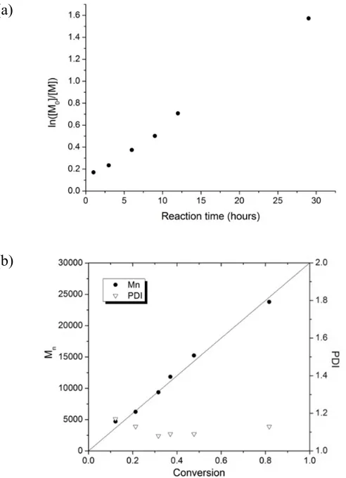
Figure 2.3 (a) Kinetics plot and (b) dependence of the molecular weight and polydispersity on the conversion for the RAFT polymerization of AHMA and MMA (1:20) ([monomer]: [CPDB]: [V-70] = 300:1:0.1, 40 °C). ...36
Figure 2.4 1H NMR spectrum of prepolymer 2 ...37
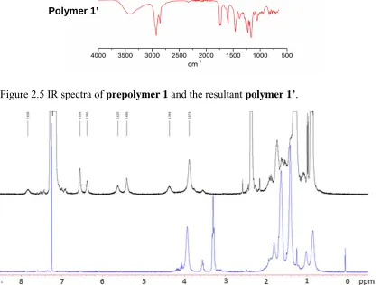
Figure 2.5 IR spectra of prepolymer 1 and the resultant polymer 1’ ...39
polymers with different loadings from 30 °C to 600 °C in nitrogen. ...40
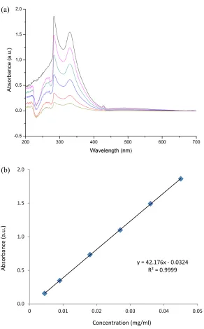
Figure 2.8 UV-vis spectra of pristine fullerene (0.0151 mg/mL), compound 1 (0.0181 mg/mL)and polymer 1’ (0.0376 mg/mL) in toluene ...42
Figure 2.9 (a) UV-vis spectra of compound 1 with various concentrations in toluene (from 0.0045 mg/ml to 0.045 mg/ml); (b) standard dependence of UV-vis absorption on concentration of compound 1 at 284 nm in toluene. ...43
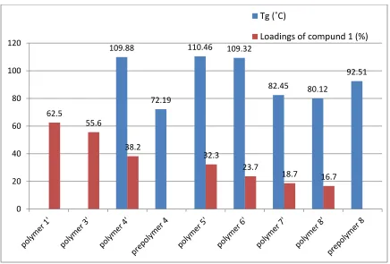
Figure 2.10 Chart of Tg and compound 1 loadings in different polymer samples ...45
Figure 2.11 GPC traces of side-chain fullerene polymer 1’, 3’, 4’ and 8’ recorded by refractive index detector ...46
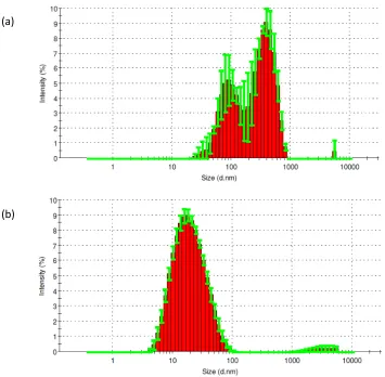
Figure 2.12 Statistical size distributions of (a) polymer 1’ and(b) polymer 4’ in toluene tested by DLS ...47
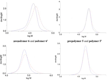
Figure 2.13 Molecular weight distributions of the SFP samples (red dash lines) and their prepolymers (blue solid lines) ...48
Figure 2.14 SEM images of polymer 1’ – 8’ ...50
Figure 2.15 GPC traces of three groups of polymers before (blue) and after (red) click reaction ...55
Figure 2.16 (a) Illustrative diagram of interactions between the TFP’s and graphene. (b) Images of graphene (0.2 mg) in toluene (left) and graphene (0.2 mg) mixed with TFP (Mn = 20,200, PDI = 1.21) in toluene (right) ...55
Figure 2.17 UV-vis spectra of (a) TFP (Mn = 20,200, PDI = 1.21) (red) and graphene (blue) in toluene; TFP solution in toluene with (b) gradual addition of graphene suspension; (c) gradual addition of TFP/graphene suspension; and (d) different concentrations. ...57
Figure 2.18 FT-IR spectra of graphene (black), TFP (Mn = 20,200, PDI = 1.21) (red) and TFP/graphene composites (blue) ...58
Figure 2.19 TEM images of the TFP (Mn = 20,200, PDI = 1.21) / graphene composites in diverse solvents: THF (top), toluene (middle) and DMF (bottom) ...59
Figure 3.1 Synthetic route of PEG-grafted Janus particles using silicon wafers as
Figure 3.2 SEM images of different sizes of silica particles immobilized on silicon wafers with different densities ...77
Figure 3.3 Phase images of different sizes of silica particles immobilized on silicon wafers with different densities captured by AFM ...77
Figure 3.4Contact angles of water on silicon wafers: (a) bare silicon wafer; (b) silicon wafer covered by silica NP’s (15 nm); (c) silicon wafer b treated with PEG-OH. ...78
Figure 3.5 Attachment of 15 nm NP’s on the surface of 500 nm particles by multiple hydrogen bonding (left) and click reaction (right) ...79
Figure 3.6 (a) Schematic illustration of the cyclic synthetic route for polymer-grafted Janus silica NP’s by combining reversible click reaction and “grafting to” strategies. (b) TEM image of azido-functionalized 500 nm particles. (c) TEM image of 500 nm particles with 15 nm NP’s attached. ...80
Figure 3.7 FT-IR spectra of azido-functionalized silica particles (500 nm) ...81
Figure 3.8 (a) C 1s and (b) Br 3d core level XPS spectra of bromo-functionalized 500 nm particles; (c) C 1s and (d) N 1s core level XPS spectra of azido-functionalized 500 nm particles. Binding energies are calibrated to aliphatic carbon at 285.0 eV. ...82
Figure 3.9 FT-IR spectra of activated5-hexynoic acidand alkynyl-functionalized silica NP’s (0.4 alkyne/nm2) ...83
Figure 3.10 FT-IR spectra of PMMA-grafted Janus silica NP’s ...85
Figure 3.11 TEM images of 500 nm particles with 15 nm NP’s attached before (left) and after (right) PMMA modification (PMMA: Mn = 13.3k, PDI = 1.11) ...86
Figure 3.12 TGA scans of alkyne-functionalized NP’s (black), PMMA-grafted Janus NP’s (red) and PMMA-grafted uniform NP’s (blue) ...87
Figure 3.13 TEM images of (a) PMMA-grafted Janus NP’s (15 nm) in THF (3.1 mg/mL); (b) PMMA-grafted Janus NP’s (15 nm) in THF (0.62 mg/mL). ...88
Figure 3.14 AFM studies on PMMA-grafted Janus NP’s ...89
Figure 3.15 TEM images showing the dispersion changes (a→d) of the PMMA-grafted Janus NP’s in DMF (0.3 mg/mL) with a gradual addition of
Figure 4.2 (a) Kinetics plot and (b) dependence of Mn and polydispersity on the
conversion for the RAFT polymerization of HMA on silica NP’s ...103
Figure 4.3 GPC traces of PHMA for kinetic studies ...104
Figure 4.4 Dependences of molecular weight and PDI on reaction time for the RAFT polymerization of (a) HMA (50 vol% in THF) at 60 °C with different ratios of CTA to monomer: 1/2000 (circle) and 1:30,000(triangle); and (b) GMA (50 vol% in THF) at 60 °C with AIBN as initiator (1.5 × 10⁻⁵ M) mediated with CTA anchored silica NP’s (1.5 × 10⁻⁴ M; 0.6 chains/nm2). ...106
Figure 4.5 (a) The precipitation of 20 kg/mol PHMA grafted NP’s with graft density of 0.6 chains/nm2 in epoxy resin. (b) TEM image of PGMA-SiO2/epoxy
nanocomposites (20 kg/mol PGMA, 0.6 chains/nm2). ...106
Figure 4.6 Designs of different rubbery interfaces on silica NP’s ...108
Figure 4.7 (a) TEM image of 1vol% PHMA-b-PGMA-SiO2 (20k20k, 0.6 chains/nm2) / epoxy nanocomposite. (b) TEM image of 1vol% PHMA-b-(PGMA-r
-PHMA)-SiO2 (20k20k, 0.6 chains/nm2) / epoxy nanocomposites. ...109
Figure 4.8 (a) Kinetics plot and (b) dependence of Mn and polydispersity on the
conversion for the RAFT polymerization of SMA in THF ...111
Figure 4.9 (a) Kinetics plot and (b) dependence of Mn and polydispersity on the conversion for the RAFT polymerization of SMA on silica NP’s (0.4
chains/nm2) in THF ...113
Figure 4.10 PP films before (left) and after (right) annealing ...114
Figure 4.11 (a) Kinetics plot and (b) dependence of Mn and polydispersity on the
conversion for the RAFT polymerization of MMA on 50 nm silica NP’s (0.14 chains/nm2) in THF ...115
Figure 4.12 Dependence of molecular weight and PDI on reaction time for the RAFT polymerization of styrene on CTA anchored silica NP’s (circle: 0.08
L
IST OFS
CHEMESScheme 1.1 General mechanism of RAFT polymerization ...2
Scheme 1.2 Proposed mechanism of Cu(I)-mediated azide-alkyne cycloaddition ...4
Scheme 1.3 Synthesis of C60-cyclopentadiene cycloadduct – N-(cycloheptyl)-endo-norbornene-5,6-dicarboximide polymers by ROMP ...8
Scheme 1.4 Synthesis of C60 end-capped polystyrene using thiol-ene chemistry ...9
Scheme 1.5 Synthetic route to fullerene-rich dendron and its linear polymer ...10
Scheme 1.6 Synthesis of CPDB functionalized silica nanoparticles ...13
Scheme 1.7 Janus nanoparticle synthesis using an emulsion process ...16
Scheme 2.1 The synthetic route for the mono-alkynyl functionalized fullerene (compound 1) ...33
Scheme 2.2 Click reaction for side chain functionalization of prepolymers ...38
Scheme 2.3 Synthesis of “tadpole-like” fullerene polymer ...52
I
NTRODUCTION1.1Reversible Addition-fragmentation Chain Transfer Polymerization
Reversible addition-fragmentation chain transfer (RAFT) polymerization has
become one of the three best-developed living radical polymerization processes (or
formally named as reversible deactivation radical polymerization) 1 over the past three
decades, together with nitroxide mediated polymerization (NMP) and atom transfer
radical polymerization (ATRP). These polymerization processes enable researchers to
simultaneously control the molecular weight and molecular weight distribution, and
provide “living” characteristics to the polymer chains. In particularly, RAFT
polymerization has been widely applied to prepare many types of polymer-based
advanced architectures due to the relatively mild reaction conditions and the tolerance to
a variety of functional groups.2-4
The RAFT process is similar to conventional free radical polymerization with the
addition of thiocarbonylthio compounds (Z-(C=S)-SR) as the chain transfer agents
(CTA’s), which are crucial to control the polymerization through a two-step
addition-fragmentation mechanism. The whole mechanism of RAFT polymerization is shown in
Scheme 1.1.5 The living characteristics rely on the dynamic equilibrium between the
active propagating radicals (Pn· and Pm·) and the dormant polymeric thiocarbonylthio
polymer chains grow with the same possibility. Additionally, the reinitiation and
propagation should also be fast enough to suppress the termination. To optimize the
control in RAFT polymerization, choosing appropriate CTA’s for different monomers is
very necessary.
Scheme 1.1 General mechanism of RAFT polymerization.
After more than ten years of development of RAFT polymerization, the correlation
between CTA structures and polymerization control has been fully studied.6 We have
known that both the ‘Z’ and ‘R’ groups of the CTA play critical roles in determining the
outcome of the polymerization. The ‘Z’ group determines the reaction rates of the
dynamic equilibrium, and generally, the rate constant of the equilibrium must be greater
than the rate of propagation. With different ‘Z’ groups, the compounds used as CTA’s
active than xanthates and dithiocarbamates, since the lone pair on nitrogen or oxygen
adjacent to the thiocarbonyl of the latter two kinds of CTA’s can reduce the transfer
coefficients in terms of their zwitterionic canonical forms. General guidelines for
selection of ‘Z’ groups are summarized in Figure 1.1.
Figure 1.1 Guidelines for selection of the ‘Z’ group of RAFT agents (ZC(=S)SR) for various monomers.6
On the other hand, the ‘R’ group of the CTA must be a good leaving group, and the
expelled radical (R·) should also be able to reinitiate polymerization efficiently.
Otherwise, retardation and termination will occur. General guidelines for selection of ‘R’
groups are summarized in Figure 1.2.
Figure 1.2 Guidelines for selection of the ‘R’ group of RAFT agents (ZC(=S)SR) for various monomers.6
1.2 Reversible Copper-mediated Click Reaction in Polymer Chemistry
In 2001, K. Barry Sharpless proposed the concept of “click chemistry”. Actually,
click chemistry is not a scientific definition, but rather a synthetic philosophy inspired by
the simple but efficient organic reactions that takes place in nature. In Sharpless’ opinion,
The reaction must be modular, wide in scope, stereospecific (but not necessarily
enantioselective), and give very high yields.
Only inoffensive byproducts are generated that can be removed by
non-chromatographic methods, such as crystallization or distillation.
The required process characteristics include simple reaction conditions (ideally, the
process should be insensitive to oxygen and water), readily available starting
materials and reagents, the use of a solvent that is benign (such as water) or easily
removed or solventless, and simple product isolation.
cycloaddition, is one of the most powerful reactions in this family. In the absence of a
proper catalyst, this cycloaddition is usually quite slow, because the ending alkynes are
not good 1,3-dipole accepters. However, when copper (I) is introduced, which can bind to
the alkynes (Scheme 1.2), the reaction rates increase dramatically with high
regioselectivity and yields.
The copper-mediated click reaction shows many advantages, such as:
introduction of azides is easily accomplished via reduction of primary amine or
substitution of halide;
azides are very stable against dimerization, hydrolysis and other organic
synthesis conditions;
the reaction can be performed in various solvents including aqueous solution.
While there have been many types of click reactions developed to date, such as the
thiol-ene reaction,9, 10 thiol-yne reaction,11 and Diels-Alder reaction,12 the
copper-mediated click reaction is still the most popular click reaction for many applications,
especially in the area of polymer synthesis.13
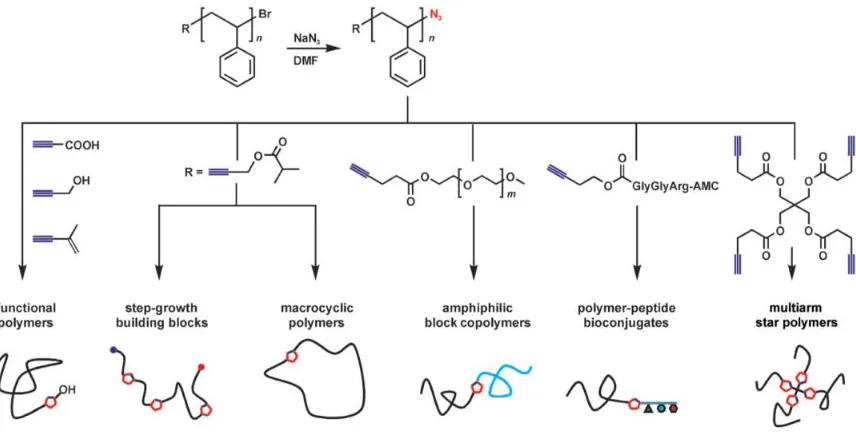
The copper-mediated click reaction is commonly used to either build up linear
polymers through step polymerization with azido/alkynyl functionalized monomers,14 or
to form dendrimers, brush polymers and block copolymers when combined with other
polymerization tequiques,15-18 such as living radical polymerization, ring opening
polymerization (ROP), and ring-opening metathesis polymerization (ROMP). For
example, the strategy developed by Li and Benicewicz was used to synthesize a variety
following the RAFT polymerization of azide-containing monomers at a relatively low
temperature (40 °C) to prevent the degradation of the azides.15 Figure 1.3 shows all the
possible polymer architectures which can be generated via combination of ATRP and the
click reaction. In addition, the click reaction also provides an effective linkage to achieve
the “grafting to” strategy for surface modification,19, 20 which will be discussed later.
Figure 1.3 Functional group interconversion for ATRP products.20
Moreover, the importance of the copper-catalyzed click reaction for polymer
chemistry is not only because it is an efficient method for forming covalent linkages, but
also because it can be used in an opposite way – cleavage of polymer chains. The
1,2,3-triazole ring formed in the click reaction is extremely robust, and for a long time it was
widely believed that the cycloreversion was not as efficient. Recently, Bielawski and
coworkers found that this linkage can be mechanically broken to recover the original
azides and alkynes by means of an ultrasound technique, if the triazole ring is in the
middle of a long polymer chain (Figure 1.4).21, 22 This mechanically-driven reaction
reactants (as a result of changes in molecular geometry) or the stabilization of reactive
intermediates at or near the transition state of the reaction coordinate. Unquestionably,
this discovery will widely broaden the application of this classic reaction in the future as
it provides a simple and powerful synthetic pathway to reversible covalent connections.
Figure 1.4 Reversible formation and cleavage of 1,2,3-triazole ring embedded within a poly(methyl acrylate) chain.21
1.3 Synthesis of Fullerene Polymers
In 1985, Kroto and coworkers first reported the existence of buckminsterfullerene
(C60).23 Five years later, the preparation of fullerene was scaled up to multigram
quantities by evaporating graphite electrodes.24 Since then, fullerene has attracted much
attention due to its unique and interesting properties, such as superconductivity,
ferromagnetism, anti-HIV bioactivity, and optical nonlinearity. Especially in the
application of polymer-based solar cells, fullerene has become the ubiquitous electron
acceptor because of the high electron affinity and ability to transport charge effectively.25
However, its applications are seriously limited because pristine fullerene has very poor
Covalent combination of fullerene with polymers is an effective strategy to
overcome this disadvantage and create novel fullerene-based architectures. After two
decades of development, a variety of fullerene-polymer structures have been synthesized
through different chemical routes. Generally, fullerene-based polymers can be classified
into the following types according to the different positions of fullerene moieties in the
polymer structures: main-chain fullerene polymers, side-chain fullerene polymers,
fullerene-capped polymers, star-shaped fullerene polymers and fullerene dendrimers.26, 27
Scheme 1.3 Synthesis of C60-cyclopentadiene cycloadduct – N-(cycloheptyl)-endo-norbornene-5,6-dicarboximide polymers by ROMP.28
Memo and coworkers synthesized a main-chain fullerene polymer using ROMP.28
They first functionalized pristine fullerene with cyclopentadiene first via a Diels-Alder
N-ruthenium catalyst (Scheme 1.3).
For the synthesis of a side-chain fullerene polymer, Hadziioannou et al. produced
styrene-based copolymers by nitroxide-mediated radical polymerization and then
introduced C60 to the side chains through either atom-transfer radical addition (ATRA)29
or cycloaddition to C6030.
Yagci and coworkers reported the fabrication of fullerene-capped polystyrene by
converting the RAFT chain end of polystyrene to a thiol group, which could subsequently
react with C60 through a thiol-ene click reaction.31 This method could be performed using
mild conditions and short reaction times.
Scheme 1.4 Synthesis of C60 end-capped polystyrene using thiol-ene chemistry.31
Natori and coworkers grafted poly(1,3-cyclohexadienyl)lithium on fullerene to form
a star-shaped fullerene polymer.32 They found that the reaction efficiency was strongly
dependent on the nucleophilicity of the polymer carbanions and the molecular weight.
Due to the steric hindrance of the attached arm and the negative charge generated on the
C60 core, up to four arms could be grafted on each fullerene molecule.
There are two architectures of fullerene dendrimers with the fullerene moiety located
dendron synthesized by Yang and coworkers, which could be further polymerized as a
macromonomer through ROMP (Scheme 1.5).33 In contrast, Martin et al. made
amphiphilic dendrofullerenes with fullerene in the core and carboxylic acids on the
branches, which displayed very interesting self-assemblies forming micelles, nanorods, or
hollow vesicles depending on the concentration.34
Scheme 1.5 Synthetic route to fullerene-rich dendron and its linear polymer.33
For the solar cell applications, there is a class of fullerene polymers named
double-cable polymers, which consists of π-conjugated backbones (donor cable) bearing
covalently connected fullerenes (acceptor cable).35, 36 This design is used to overcome the
poor compatibility between the conjugated polymer and the fullerene components, which
generate block copolymers bearing both conjugated blocks and fullerene blocks,37, 38
since the micro-phase separation of amphiphilic block copolymers has been well studied.
1.4 Surface Modification of Nanoparticles with Polymers
Nanoparticles are of great scientific and practical interest as they are effectively a
bridge between bulk materials and molecular structures, and display many intriguing
size-dependent properties. Covalently grafting polymer brushes on their surface has
extensively broadened the applications of nanoparticles in recent years, as the
modification can greatly improve their compatibility with organic/polymer matrices, and
optimize the surface chemistry for optical, mechanical and biomedical applications.39-43
Overall, there are two principal synthetic strategies for grafting polymers on
nanoparticles: the “grafting to” and “grafting from” strategies (Figure 1.5). As the term
implies, in the “grafting to” approach polymers are produced first, and then attached to
the surface of nanoparticles with proper end functional groups.44-48 Since polymer
synthesis and grafting are performed in separate steps, this approach is universal and
many types of polymerization methods can be applied regardless of the surface chemistry
of nanoparticles. However, it is not possible to attain high graft densities using “grafting
to” strategies because it is difficult for the end-functionalized polymer chains to diffuse
near the nanoparticle surface after some grafting sites have been occupied by the
earlier-grafted polymers due to steric hindrance, especially when the molecular weight of the
polymer is high. Moreover, the existence of many free polymers after the grafting can
create difficulties in purification. In contrast, chain initiators are anchored on the
nanoparticle surface in the “grafting from” strategies, which can usually have a relatively
initiators during the polymerization, and polymers grow from the surface.49-52 The
success of this strategy only requires the diffusion of small monomeric species to the
surface of the nanoparticles. While very few polymerization methods can tolerate the
extremely high local concentration of chain initiators on the nanoparticle surface and still
maintain good control, so far living radical polymerization is the most popular method for
grafting polymer “from” the surface of nanoparticles.
Figure 1.5 The “grafting to” and “grafting from” strategies for grafting polymers on nanoparticles.
Nanoparticle modification via RAFT polymerization has been investigated for more
than ten years due to its versatility and simplicity,53 which is usually achieved by
anchoring either the “Z” group or the “R” group of CTA on the nanoparticle surface.
Following the “Z” approach, polymer brushes act as the leaving groups (Pn·) and are not
always attached on the surface of the nanoparticles. Thus, the propagation actually occurs
in the solution, so it is more like a “graft to” strategy.54, 55 However, to undergo a
well-controlled RAFT polymerization, the propagating polymer radicals have to be close to
the surface to maintain the chain-transfer reaction with the CTA’s. Because of the steric
hindrance of the neighboring grafted polymer chains, the polymerization control of the
“Z” approach is relatively poor. The propagating polymer radicals may drift away from
the nanoparticle surface during the polymerization, leading to decreased graft density and
attracted more attention from the scientific community. Since the “R” groups are
anchored on the surface, the whole nanoparticle acts as part of the leaving groups. Thus,
the propagating polymer radicals are always on the surface during the polymerization. In
previous work from our group, Li and Benicewicz have designed a mature pathway to
anchor a CTA – 4-cyanopentanoic acid dithiobenzoate (CPDB) on silica nanoparticles
(SiO2) with precisely tunable graft density (Scheme 1.6), and conducted well-controlled
RAFT polymerization of different monomers on the nanoparticles.56 In addition to
dithioester-type CTA’s, trithiocarbonates have also been anchored on nanoparticles,
which are claimed to be more robust and universal.57
Scheme 1.6 Synthesis of CPDB functionalized silica nanoparticles.
Although the previous discussion has focused on uniformly-functionalized
homopolymer-grafted nanoparticles, more complicated architectures composed of
polymer brushes and nanoparticles can be conducted with appropriate graft strategies. In
terms of polymer composition, random copolymers, block copolymers, and even gradient
with more than one kind of species, such as binary brush grafted nanoparticles.58, 59 There
have also been attempts to prepare nanoparticles that are asymmetrically functionalized
with different polymers to form Janus nanoparticles. These advanced structures will open
up many new possibilities for the application of nanoparticles as smart or
multi-functioned materials.
1.5 Synthesis of Janus particles
Figure 1.6 Schematic representation of the synthetic routes yielding Janus particles.64
The introduction of anisotropy into micro or nano sized particles is an intriguing and
challenging research area in current materials science, since it has been theoretically
predicted that anisotropic particles could be very useful for controlling molecular
recognition and self-assembling processes.60-62 Janus particles, were first proposed by
P-G. de Gennes,63 and are a type of particle that contains different chemistries on the two
hemispheres of the particle. In 2005, Perro et al. reviewed the research on Janus particle
synthesis after fifteen years of development and summarized the most typical synthetic
dozens of micrometers.
More recently, research efforts have focuses on even smaller particles with more
precise control over the geometry of the Janus particles. For instance, Wang and
coworkers stabilized negatively charged gold nanoparticles (Au NPs) in organic solvents
assisted by amphiphilic poly(ethylene glycol)-octa-functionalized polyhedral oligomeric
silsesquioxane, and then mixed it with an aqueous solution containing positively charged
silica nanoparticles (SiO2 NPs), inducing the interface conjugation of negative Au NPs
and positive SiO2 NPs through electrostatic interactions and leading to the formation of
patchy Janus nanoparticles.65 Paunov and Cayre used a gel trapping technique to form
monolayers of polystyrene microparticles on an oil-water interface, and then lifted off the
particles by casting with PDMS elastomer to generate Janus particles.66 Similarly, Tang
and coworkers prepared monolayers of microparticles on glass slides and coated the
exposed surface of the particles with gold. After release from the glass slides by
sonication, the two hemispheres of the Janus particles were functionalized by two kinds
of proteins using different chemistry for potential biomedical applications.67
The emulsion approach developed by Granick et al is one of the most successful
synthetic routes for Janus particles so far, and gram-sized quantities could be achieved
using this approach.68 At the liquid-liquid interface of emulsified molten wax and water,
untreated silica particles adsorb and are frozen in place when the wax solidifies. The
exposed surfaces of the immobilized particles are modified chemically. After the wax is
dissolved, the inner surfaces can be modified with a different chemistry (Scheme 1.7). By
angle of silica particles on the interface can be varied. Consequently, the ratio of the two
hemispheres of the Janus particles can be adjusted.69 Moreover, they also developed a
two-step μ-contact printing method to form a more complicated structure – trivalent
patchy particles.70
Scheme 1.7 Janus nanoparticle synthesis using an emulsion process.68
1.6 Motivation and outline
The development of modern synthetic techniques in organic and polymer chemistry
has introduced many novel and efficient reactions into the toolbox for polymer synthesis
and nanoparticle modification.15,71 In this research, we used these modern synthetic tools
to overcome two major challenges in polymer functionalized nanomaterials and advance
our understanding of their self-assembly behaviors.
In the first part of this work, carbon-nased materials ,such as fullerene, graphene, etc,
polymer matrices is expected. As described in Chapter 2 of this dissertation, both
side-chain fullerene polymers and “tadpole-like” fullerene polymers were designed through a
combination of RAFT polymerization and click reaction. Due to the high efficiency of
the two techniques, the molecular weight, fullerene loading and polymer architecture of
the side-chain fullerene polymers were controlled precisely and simultaneously, which
represnts a significant progress in comparison to the previously reported synthetic
approaches. Additionally, the ability of the “tadpole-like” fullerene polymers to function
as surfactants was studied to stabilize graphene in different solvents through strong π-π
stacking interactions.
Another aspect of this research was focused on the surface modification of silica
nanoparticles with polymers in unique ways. In Chapter 3, a novel,
mechanochemically-driven and cyclic synthetic route is designed for the fabrication of polymer-grafted Janus
nanoparticles, using the recently-reported reversible click reaction, Previous to this
research there were no effective synthetic methods reported in this field to prepare
polymer-grafted Janus nanoparticles with diameters less than 100 nm. Additionally,
growing polymer brushes is an effective strategy to adjust the dispersion of the
nanoparticles in polymeric nanocomposites. Therefore, the final chapter focuses on
exploring the polymerizations of different functional monomers on silica nanoparticles
via surface-initiated RAFT polymerization, and studying the dispersions of the resultant
polymer-grafted nanoparticles in the corresponding matrices. In addition to
investigated to form multi layers of polymer brushes, capable of creating pseudo-gradient
brush structures in a robust and straightforward manner.
1.7 References
1. Jenkins, A. D.; Jones, R. G.; Moad, G. Pure Appl. Chem. 2010,82, 483-491.
2. Hrsic, E.; Zografou, I.; Schulte, B.; Pich, A.; Keul, H.; Moller, M. Polymer 2013,54, 495-504.
3. Quek, J. Y.; Roth, P. J.; Evans, R. A.; Davis, T. P.; Lowe, A. B. J. Polym. Sci. Pol. Chem. 2013,51, 394-404.
4. Xu, J. X.; Xiao, X.; Zhang, Y. Y.; Zhang, W. Q.; Sun, P. C. J. Polym. Sci. Pol. Chem.
2013,51, 1147-1161.
5. Moad, G.; Chiefari, J.; Chong, Y. K.; Krstina, J.; Mayadunne, R. T. A.; Postma, A.; Rizzardo, E.; Thang, S. H. Polym. Int. 2000,49, 993-1001.
6. Keddie, D. J.; Moad, G.; Rizzardo, E.; Thang, S. H. Macromolecules 2012, 45, 5321-5342.
7. Kolb, H. C.; Finn, M. G.; Sharpless, K. B. Angew. Chem. Int. Edit. 2001, 40, 2004-2021.
8. Bock, V. D.; Hiemstra, H.; van Maarseveen, J. H. Eur. J. Org. Chem. 2005, 51-68.
9. Lowe, A. B. Polym. Chem. 2010,1, 17-36.
10. Kotsuchibashi, Y.; Ebara, M.; Aoyagi, T.; Narain, R. Polym. Chem. 2012, 3, 2545-2550.
11. Fairbanks, B. D.; Sims, E. A.; Anseth, K. S.; Bowman, C. N. Macromolecules 2010,
43, 4113-4119.
12. Blackman, M. L.; Royzen, M.; Fox, J. M. J. Am. Chem. Soc. 2008, 130, 13518-13519.
13. Lutz, J.-F. Angew. Chem. Int. Edit. 2007,46, 1018-1025.
14. Chernykh, A.; Agag, T.; Ishida, H. Polymer 2009,50, 382-390.
15. Li, Y.; Yang, J.; Benicewicz, B. C. J. Polym. Sci. Pol. Chem. 2007,45, 4300-4308.
3928-3932.
18. Chen, J. C.; Xiang, J. M.; Cai, Z. W.; Yong, H.; Wang, H. D.; Zhang, L. H.; Luo, W. Q.; Min, H. J. Macromol. Sci. Part A-Pure Appl. Chem. 2010,47, 655-662.
19. An, Z.; Tang, W.; Wu, M.; Jiao, Z.; Stucky, G. D. Chem. Commun. 2008, 6501-6503.
20. Liu, J.; Nie, Z.; Gao, Y.; Adronov, A.; Li, H. J. Polym. Sci. Pol. Chem. 2008, 46, 7187-7199.
21. Brantley, J. N.; Wiggins, K. M.; Bielawski, C. W. Science 2011,333, 1606-1609.
22. Leibfarth, F. A.; Hawker, C. J. Science 2011,333, 1582-1583.
23. Kroto, H. W.; Heath, J. R.; O'Brien, S. C.; Curl, R. F.; Smalley, R. E. Nature 1985,
318, 162-163.
24. Kratschmer, W.; Lamb, L. D.; Fostiropoulos, K.; Huffman, D. R. Nature 1990, 347, 354-358.
25. Thompson, B. C.; Frechet, J. M. J. Angew. Chem. Int. Edit. 2008,47, 58-77.
26. Giacalone, F.; Martin, N. Chem. Rev. 2006,106, 5136-5190.
27. Wang, C. C.; Guo, Z. X.; Fu, S. K.; Wu, W.; Zhu, D. B. Prog. Polym. Sci. 2004,29, 1079-1141.
28. Mamo, M. A.; Freitas, F. S.; Forbes, R. P.; Black, R. S.; Nogueira, A. F.; van Otterlo, W. A. L.; Coville, N. J. Fuller. Nanotub. Carbon Nanostruct. 2013,21, 198-212.
29. de Boer, B.; Stalmach, U.; van Hutten, P. F.; Melzer, C.; Krasnikov, V. V.; Hadziioannou, G. Polymer 2001,42, 9097-9109.
30. Barrau, S.; Heiser, T.; Richard, F.; Brochon, C.; Ngov, C.; van de Wetering, K.; Hadziioannou, G.; Anokhin, D. V.; Ivanov, D. A. Macromolecules 2008, 41, 2701-2710.
31. Iskin, B.; Yilmaz, G.; Yagci, Y. Chem.-Eur. J. 2012,18, 10254-10257.
32. Natori, I.; Natori, S. J. Polym. Sci. Pol. Chem. 2008,46, 3282-3293.
33. Kim, J.; Yun, M. H.; Lee, J.; Kim, J. Y.; Wudl, F.; Yang, C. Chem. Commun. 2011,
34. Munoz, A.; Illescas, B. M.; Sanchez-Navarro, M.; Rojo, J.; Martin, N. J. Am. Chem. Soc. 2011,133, 16758-16761.
35. Lanzi, M.; Paganin, L.; Errani, F. Polymer 2012,53, 2134-2145.
36. Miyanishi, S.; Zhang, Y.; Hashimoto, K.; Tajima, K. Macromolecules 2012, 45, 6424-6437.
37. Heuken, M.; Komber, H.; Erdmann, T.; Senkoyskyy, V.; Kiriy, A.; Voit, B.
Macromolecules 2012,45, 4101-4114.
38. Bicciocchi, E.; Chen, M.; Rizzardo, E.; Ghiggino, K. P. Polym.Chem. 2013,4, 53-56.
39. Lin, I. C.; Liang, M. T.; Liu, T. Y.; Jia, Z. F.; Monteiro, M. J.; Toth, I. Bioorg. Med. Chem. 2012,20, 6862-6869.
40. Park, J. T.; Roh, D. K.; Patel, R.; Kim, E.; Ryu, D. Y.; Kim, J. H. J. Mater. Chem.
2010,20, 8521-8530.
41. Shi, H. Y.; Yuan, L.; Wu, Y. F.; Liu, S. Q. Biosens. Bioelectron. 2011, 26, 3788-3793.
42. Tao, P.; Li, Y.; Rungta, A.; Viswanath, A.; Gao, J. N.; Benicewicz, B. C.; Siegel, R. W.; Schadler, L. S. J. Mater. Chem. 2011,21, 18623-18629.
43. Yang, J.; Deng, L. H.; Han, C. R.; Duan, J. F.; Ma, M. G.; Zhang, X. M.; Xu, F.; Sun, R. C. Soft Matter 2013,9, 1220-1230.
44. Lowe, A. B.; Sumerlin, B. S.; Donovan, M. S.; McCormick, C. L. J. Am. Chem. Soc.
2002,124, 11562-11563.
45. Lupitskyy, R.; Motornov, M.; Minko, S. Langmuir 2008,24, 8976-8980.
46. Feng, L. B.; He, L.; Ma, Y. X.; Wang, W. Mater. Chem. Phys. 2009,116, 158-163.
47. Thong-On, B.; Rutnakornpituk, B.; Wichai, U.; Rutnakornpituk, M. J. Nanopart. Res.
2012,14.
48. Wang, Y. Z.; Fan, D. Q.; He, J. P.; Yang, Y. L. Colloid Polym. Sci. 2011,289, 1885-1894.
49. Bartholome, C.; Beyou, E.; Bourgeat-Lami, E.; Chaumont, P.; Zydowicz, N.
Macromolecules 2003,36, 7946-7952.
52. Rutot-Houze, D.; Fris, W.; Degee, P.; Dubois, P. J. Macromol. Sci. Pure 2004, A41, 697-711.
53. Raula, J.; Shan, J.; Nuopponen, M.; Niskanen, A.; Jiang, H.; Kauppinen, E. I.; Tenhu, H. Langmuir 2003,19, 3499-3504.
54. Stenzel, M. H.; Zhang, L.; Huck, W. T. S. Macromol. Rapid Commun. 2006, 27, 1121-1126.
55. Zhao, Y.; Perrier, S. Macromolecules 2006,39, 8603-8608.
56. Li, C.; Han, J.; Ryu, C. Y.; Benicewicz, B. C. Macromolecules 2006,39, 3175-3183.
57. Ohno, K.; Ma, Y.; Huang, Y.; Mori, C.; Yahata, Y.; Tsujii, Y.; Maschmeyer, T.; Moraes, J.; Perrier, S. Macromolecules 2011,44, 8944-8953.
58. Rungta, A.; Natarajan, B.; Neely, T.; Dukes, D.; Schadler, L. S.; Benicewicz, B. C.
Macromolecules 2012,45, 9303-9311.
59. Zhao, B.; He, T. Macromolecules 2003,36, 8599-8602.
60. Vaia, R. A.; Wagner, H. D. Mater. Today 2004,7, 32-37.
61. Zhang, Z. L.; Glotzer, S. C. Nano Letters 2004,4, 1407-1413.
62. Vanakaras, A. G. Langmuir 2006,22, 88-93.
63. Degennes, P. G. Angew. Chem. Int. Edit. 1992,31, 842-845.
64. Perro, A.; Reculusa, S.; Ravaine, S.; Bourgeat-Lami, E. B.; Duguet, E. J. Mater. Chem. 2005,15, 3745-3760.
65. Wang, F.; Phonthammachai, N.; Mya, K. Y.; Tjiu, W. W.; He, C. Chem. Commun.
2011,47, 767-769.
66. Paunov, V. N.; Cayre, O. J. Adv. Mater. 2004,16, 788-791.
67. Tang, J. L.; Schoenwald, K.; Potter, D.; White, D.; Sulchek, T. Langmuir 2012, 28, 10033-10039.
68. Hong, L.; Jiang, S.; Granick, S. Langmuir 2006,22, 9495-9499.
70. Jiang, S.; Granick, S. Langmuir 2009,25, 8915-8918.
71. Li, Y.; Benicewicz, B. C. Macromolecules 2008,41, 7986-7992.
CHAPTER
2
S
YNTHESIS OFF
ULLERENEP
OLYMER VIAC
OMBINATION OFRAFT
P
OLYMERIZATION ANDC
LICKR
EACTION2.1Introduction
As discussed in Chapter 1, the covalent incorporation of fullerene into polymer
architectures can significantly improve the compatibility of fullerene and expand it
applications. According to the different positions of C60 moieties in the polymer
structures, fullerene-based polymers can be categorized into the following types:
main-chain fullerene polymers, side-main-chain fullerene polymers (SFP’s), fullerene-capped
polymers, star-shaped fullerene polymers and dendrimers.1,2 Synthesis of polymers with
C60 units in the main chain involves fullerene-based monomers having two reacting sites,
which are relatively difficult to produce and purify, and a slight amount of
multi-functionalized fullerene impurities can result in severe cross-linking during the
polymerization.3 Fullerene star-shaped polymers have also been prepared.4 These
polymers usually exhibit excellent solubility and compatibility due to the high content of
polymer portion, but cannot have high C60 loadings because fullerene moieties only exist
in the cores of the “stars”. C60-containing dendrimers are another type of interesting
architecture, but typically prepared as low molecular weight materials.5-7
In contrast, SFP’s can have relatively well-defined strucutres, high C60 loadings and
molecular weights simultaneously, although their syntheses can be quite challenging.
monomers.8 Because of the steric hindrance of the C60 moieties, the degree of
polymerization was very low. Alternatively, anchoring C60 moieties on preformed
polymers (“grafting to” strategy) can avoid the steric hindrance during polymerization,
but an efficient reaction is needed to achieve a controlled attachment. In a recent
publication from the same group, a “rod-coil” diblock copolymer containing
poly(3-hexylthiophene) (P3HT) and fullerene was synthesized through a combination of RAFT
polymerization strategy and a subsequent polymer-analogous cycloaddition.9 A similar
block copolymer was reported by Jo et al., but the “coil” block was formed by ATRP and
the attachment was achieved via a carboxylic acid-alcohol coupling reaction.10
Hadziioannou et al. copolymerized 4-chloromethylstyrene and styrene by NMP and then
attached C60 through via an atom-transfer radical addition (ATRA) or a cycloaddition to
C60.11,12 Through a direct fullerenation, Celli et al. prepared polysulfone with fullerene
randomly connected to the side chains.13 Yang et al. postfunctionalized the side chain of
a P3HT derivative with C60 by adding sarcosine to create a phenyl linking bridge.14 Also,
Rusen et al. made C60-grafted polyethylene at 100 °C based on the reaction of C60 with
amino groups which were introduced earlier along the polymer main chains.15 However,
in most of these cases the architectures and C60 loadings were not well controlled,
because it was difficult to prevent multiple reactions on the same C60 molecule when
pristine fullerene was involved in the attachment process. Generally, the methods of
attachment were not effective enough to make polymers possessing carefully adjustable
fullerene contents.
Herein, we describe our work on the fabrication of SFP’s by combining RAFT
feature good control, mild reaction conditions and functional group tolerance, the
combination is expected to be a convenient approach to prepare well-defined linear
SFP’s. Methacrylate-based monomers were chosen to prepare the backbones because of
its relatively good compatibility with fullerene,10,16,17 and also its mechanical properties,
optical transparency and stability to photo ageing.18 Moreover, the synthesis of a soluble
and mono-functionalized fullerene derivative for the post-functionalization is depicted
which prevented cross-linking of the polymer chains.
Additionally, the assembly behaviors of the prepared polymers were investigated in
solution by gel permeation chromatography (GPC) and dynamic light scattering (DLS),
and on solid substrates using scanning electron microscopy (SEM). The SFP’s displayed
a variety of self-aggregation behaviors. The SEM images of the SFP’s on silica wafers
showed the formation of various nanoparticle assemblies and crystalline-like clusters
depending on fullerene contents and chain lengths of the SFP samples. The study of the
self-assembly of fullerene derivatives into supramolecular architectures is always a
significant challenge.19-21 Although many such investigations were performed on
fullerene dendrimers 7,22 and fullerene-capped polymers 23-25, to the best of our
knowledge, detailed morphology studies on SFP’s had not been reported by the time
when we started this research.
On the other hand, graphene has become one of the most popular carbon materials in
recent years because its unique two dimensional hexagonal carbon network leads to
extraordinary mechanical properties, high thermal conductivity, and interesting optical
properties.26 However, single graphene sheets have strong tendency to agglomerate
been widely used instead, which has better solubility, but the defects in the aromatic
structure may impair the outstanding properties in contrast with graphene. Liu and
coworkers utilized pyrene-terminal polymers to functionalize graphene through π-π
stacking interactions and produced thermosensitive graphene nanocomposites.27 This
kind of non-covalent attachment between pyrene and graphene resulted in a greatly
enhanced solubility of graphene without damaging its aromatic structure.
In this context, we designed a fullerene-capped polymer with two polymeric tails
and named it as “tadpole-like” fullerene polymer (TFP). The tail parts were synthesized
by RAFT polymerization involving azido-capped CTA’s, and then anchored on the
fullerene “head” though a copper-mediated click reaction. The amphiphilic TFP bearing
two solvophilic tails and a “graphene-philic” head were further studied as surfactant to
improve the solubility of graphene in diverse solvents. Using this method, polymer tails
are supposed to stabilize the graphene sheets in a variety of solvents or matrices
depending on the nature of polymer. Meanwhile, the combination of fullerene and
graphene is expected to create a new class of photovoltaic active materials with a strong
electron-accepting capability of fullerene and good charge transport properties associated
with graphene.28,29 UV-vis and FT-IR spectroscopies were applied to demonstrate the π-π
stacking interactions between the TFP and graphene.
2.2 Experimental Section
2.2.1 Materials
Fullerene (C60) was purchased from SES Research and used as received.
Tetrahydrofuran (THF) (99.9%, Acros) was dried over CaH2 overnight and distilled
before use. 4-Cyanopentanoic acid dithiobenzoate (CPDB) was purchased from Strem
through a basic alumina column to remove inhibitors before use.
2,2’-Azobis(4-methoxy-2,4-dimethyl valeronitrile) (V-70) was purchased from Wako Chemicals and used as
received. Graphene was purchased from Angstron Materials and used as received. Unless
otherwise specified, all chemicals were purchased from Fisher Scientific and used as
received.
2.2.2 Instrumentation
Nuclear magnetic resonance (NMR) spectra were recorded on Varian Mercury 300
and 400 spectrometers using CDCl3 as the solvent. Matrix-assisted laser
desorption-ionization time-of-flight mass spectrometry (MALDI-TOF-MS) was performed with a
Bruker Ultraflex MALDI tandem time-of-flight mass spectrometer. Fourier transform
infrared spectroscopy (FT-IR) spectra were recorded using a PerkinElmer Spectrum 100
FT-IR Spectrometer. Molecular weights and polydispersity indices (PDI = Mw/Mn) were
determined using a Waters gelpermeation chromatograph equipped with a 515 HPLC
pump, a 2410 refractive index detector, and three Styragel columns (HR1, HR3, HR4 in
the effective molecular weight range of 100-5000, 500-30 000, and 5000-500 000,
respectively) with THF as the eluent at 30 °C and a flow rate of 1.0 mL/min. The GPC
system was calibrated with poly(methyl methacrylate) from Polymer Laboratories. The
thermal stability of the polymers was determined by thermogravimetric analysis (TGA)
performed on vacuum-dried polymer samples from 30 °C to 600 °C using a TA
Instruments Q5000 with a nitrogen flow rate of 20 mL/min and heating rate of 10
°C/min. UV-vis absorption spectra were taken on a Perkin-Elmer Lamda 4C UV/vis
spectrophotometer. The glass transition temperatures (Tg) of the polymer samples were
measured by differential scanning calorimetry (DSC) using a TA Instruments Q2000 with
to 150 °C at a heating rate of 10 ºC/min, which were then cooled from 150 °C to 30 ºC at
a heating rate of 20 ºC/min, followed by a second-round heating step at a heating rate of
20 ºC/min. The DSC curves were obtained from the second heat cycle. The DLS
experiment was carried out using a Zetasizer Nano S instrument. The laser wavelength
was 633 nm and the detector position was at 173 ̊. SEM images were captured using a
Zeiss Ultraplus Thermal Field Emission Scanning Electron Microscope, and the samples
were prepared on silicon wafers by spin-coating.
2.2.3 Synthesis of 3,5-bis(octyloxy)phenyl methanol (2) and 3-(3,5-bis (octyloxy)benzyl oxy)-3-oxopropanoic acid (3)
The syntheses of compounds 2 and 3 were carried out according to the methods in
the literature.30
2.2.4 Synthesis of 3,5-bis(octyloxy)benzyl propy-2-nyl malonate (4)
Compound 3 (6.31 g, 14 mmol), propargyl alcohol (788 mg, 14 mmol) and
4-(dimethylamino) pyridine (DMAP) (512 mg, 4.7 mmol) were dissolved in methylene
chloride (100 mL). Dicyclohexylcarbodiimide (DCC) (2.89 g, 14 mmol) in 30 mL of
methylene chloride was added dropwise into the solution with stirring at 0 °C. The
mixture was allowed to slowly warm to room temperature and, after stirring overnight,
filtered and evaporated. Silica gel column chromatography (3:2 mixture of hexane and
methylene chloride) yielded compound 4 as a colorless oil (5.41 g, 79%). 1H NMR (300
MHz, CDCl3): δ = 0.88 (t, J = 6.6 Hz, 6H, CH3), 1.37 (m, 20H, CH3(CH2)5CH2CH2O),
1.74 (m, 4H, CH3(CH2)5CH2CH2O), 2.49 (t, J = 2.3 Hz, 1H, C≡CH), 3.48 (s, 2H,
OCCH2CO), 3.92 (t, J = 6.5 Hz, 4H, CH3(CH2)6CH2O), 4.73 (d, J = 1.2 Hz, 2H,
CH2C≡CH), 5.09 (s, 2H, PhCH2O), 6.40 (d, J = 2.4 Hz, 1H, Ar), 6.46 (d, J = 2.1 Hz, 2H,
41.04, 52.75, 67.20, 67.93, 75.42, 75.50, 101.09, 106.31, 137.19, 160.41, 165.53, 165.75.
FT-IR: 1741 cm-1 (C=O) and 3291 cm-1 (C≡CH). HRMS (EI): calcd. for C29H44O6 [M]+
488.3124; found 488.3138.
2.2.5 Synthesis of mono-alkynyl functionalized fullerene (1)
1,8-Diazabicyclo[5.4.0]undec-7-ene (DBU) (0.310 mL, 2.08 mmol) was added at
room temperature to a solution of compound 4 (447 mg, 0.915 mmol), C60 (600 mg,
0.832 mmol), and iodine (264 mg, 1.04 mmol) in toluene (600 mL), and the mixture was
stirred for 7 hours. The mixture was filtered through a short plug of silica gel and washed
by methylene chloride (100 mL). Silica gel column chromatography (1:1 mixture of
hexane and toluene) yielded compound 1 as dark red glassy solids (547 mg, 54%). 1H
NMR (300 MHz, CDCl3): δ = 0.89 (m, 6H, CH3), 1.36 (m, 20H, CH3(CH2)5CH2CH2O),
1.75 (m, 4H, CH3(CH2)5CH2CH2O), 2.60 (t, J = 2.6 Hz, 1H, C≡CH), 3.91 (t, J = 6.5 Hz,
4H, CH3(CH2)6CH2O), 5.04 (d, J = 2.1 Hz, 2H, CH2C≡CH), 5.45 (s, 2H, PhCH2O), 6.42
(d, J = 2.7 Hz, 1H, Ar), 6.61 (d, J = 2.1 Hz, 2H, Ar). 13C NMR (400 MHz, CDCl3): δ =
14.12, 22.68, 26.12, 29.27, 29.39, 31.83, 51.26, 54.41, 68.16, 69.16, 71.18, 101.70,
107.25, 136.42, 138.93, 139.38, 140.89, 140.95, 141.84, 141.86, 142.19, 142.20, 142.96,
142.99, 143.01, 143.05, 143.84, 143.87, 144.53, 144.67, 144.71, 144.90, 144.91, 145.02,
145.15, 145.17, 145.24, 145.29, 160.49, 162.86, 163.13. FT-IR: 1749 cm-1 (C=O) and
3302 cm-1 (C≡CH). MALDI-TOF-MS: calcd. for C89H42O6 [M + Na]+ 1229.28; found
1229.3.
2.2.6 Synthesis of bi-alkynyl functionalized fullerene (5)
The synthesis of compound 5 was carried out according to the methods reported in
2.2.7 Synthesis of 6-azidohexyl 4-cyano-4-(phenylcarbonothioylthio)pentanoate (azido-functionalized CPDB).
1-Azido-6-hydroxyhexane was synthesized according to the methods published
previously.32 CPDB (878 mg, 3.15 mmol), 1-azido-6-hydroxyhexane (500 mg, 3.49
mmol), and dicyclohexylcarbodiimide (DCC) (720 mg, 3.49 mmol) were dissolved in 30
mL of dichloromethane. (Dimethylamino)pyridine (DMAP) (128 mg, 1.05 mmol) in 5
mL of dichloromethane was added slowly to the solution, which was stirred at room
temperature overnight. The solution was filtered to remove the salt. After removal of
solvent and silica gel column chromatography (10:1 mixture of hexane and ethyl acetate),
azido-functionalized CPDB, was obtained as a dark red oil (798 mg, 63% yield). 1H
NMR (300 MHz, CDCl3): δ = 1.35-1.39 (m, 4H, N3CH2(CH2)2), 1.54-1.66 (m, 4H,
N3(CH2)3(CH2)2), 1.91 (s, 3H, CH3), 2.36-2.69 (m, 4H, C(CH2)2(C=O)O), 3.24 (t, J = 6.8
Hz, 2H, CH2N3), 4.09 (t, J = 6.6 Hz, 2H, CH2OC=O), 7.37 (t, J = 7.8 Hz, 2H, Ar), 7.54 (t,
J = 7.4 Hz, 1H, Ar), 7.88 (dd, J1,2 = J3,4 = 1.2 Hz, J1,3 =J2,4 =8.4 Hz, 2H, Ar). 13C NMR
(400 MHz, CDCl3): δ = 24.09, 25.48, 26.32, 28.39, 28.70, 29.79, 33.40, 45.75, 51.28,
64.94, 118.49, 126.66, 128.57, 133.06, 144.48, 171.54, 222.33. FT-IR: 1181 cm-1
(PhC=S), 1732 cm-1 (C=O), 2094 cm-1 (N3). HRMS (EI): calcd. for C19H24N4O2S2 [M]+
404.1341; found 404.1347.
2.2.8 Synthesis of 6-azidohexyl methacrylate (AHMA)
The synthesis of AHMA was carried out according to the methods published
previously.32
Caution: special care should be taken to minimize the possible hazards in the
preparation and handling of the azide compounds.
Typically, a solution of AHMA (0.22 g), methyl methacrylate (MMA) (1.0 g),
4-cyanopentanoic acid dithiobenzoate (CPDB) (10.5 mg, 37 μmol/g), V-70 (1.05 mg, 3.4
μmol/g), and THF (1.2 mL) were prepared in a dried Schlenk tube. The mixture was
degassed by three freeze-pump-thaw cycles, backfilled with nitrogen, and then placed in
an oil bath at 40 °C for various intervals. The polymerization solution was quenched in
ice water and poured into an aluminum boat. The solvent and monomer were removed by
evaporation in a fume hood overnight and then one day under vacuum. Monomer
conversion was determined by gravimetric analysis, molecular weight characteristics
were analyzed by GPC, and proportion of each residue analyzed via 1H NMR. The feed
ratios varied according to the requirements for different random copolymers.
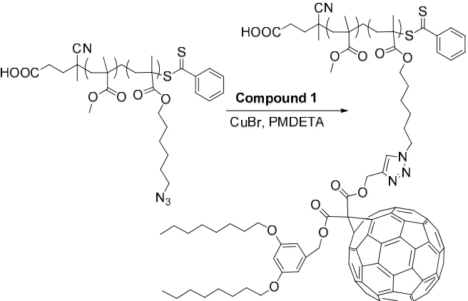
2.2.10 Typical Click reaction between poly(MMA-r-AHMA) and alkynyl functionalized fullerene (1)
A sample of poly(MMA-r-AHMA) with a known proportion of each residue was
reacted with compound 1 for example: Poly(MMA-r-AHMA) (Mn = 15,718, PDI = 1.15,
[AHMA]:[MMA] = 1:11) (200 mg, 1 equiv. of N3), compound 1 (202 mg, 1.1 equiv. of
alkyne), and N,N,N',N',N"-pentamethyldiethylene triamine (PMDETA) (16 μL, 0.5
equiv.) were dissolved in toluene (50 mL). The solution was degassed by bubbling
nitrogen for 30 min and then CuBr (11 mg, 0.5 equiv.) was added. The mixture was
stirred under nitrogen protection at room temperature for one day. The mixture was then
diluted with methylene chloride and passed through neutral alumina to remove the copper
catalyst and unreacted fullerene compound 1. After concentration by rotary evaporation,
the product was precipitated in hexane, filtered, and dried under vacuum. The feed ratios
can be different when polymers with different components involved.
A solution of MMA (1.0 g, 10 mmol), azido-functionalized CPDB (13.4 mg, 33
μmol), V-70 (3.3 μmol), and THF (1.0 mL) was prepared in a dried Schlenk tube. The
mixture was degassed by three freeze-pump-thaw cycles, back filled with nitrogen, and
then placed in an oil bath at 40 °C for 15 hours. The polymerization solution was
quenched in ice water and the resultant azido-capped polymer was precipitated in hexane.
Molecular weight characteristics were analyzed by GPC.
2.2.12 Typical Click reaction for synthesis of fullerene-capped poly(methyl methacrylate) (TFP)
A solution of compound 5 (7.74 mg, 8 mmol), N3-PMMA (Mn = 9.9k, PDI = 1.14,
160 mg, 16 mmol) and PMDETA (1.7 µL, 8 mmol) in toluene was degassed by nitrogen
flashing for 30 min, and then CuBr (1.2 mg, mmol) was added. The mixture was stirred
under nitrogen protection at room temperature for one day. The mixture was then diluted
with methylene chloride and passed through neutral alumina to remove the copper
catalyst. After concentration by rotary evaporation, the product was precipitated in
hexane, filtered, and dried under vacuum. Molecular weight characteristics were analyzed
by GPC. The amounts of N3-PMMA varied depending on diverse molecular weights.
2.3 Results and Discussion
2.3.1 Modification of pristine fullerene
A highly soluble fullerene derivative compound 1 with a “clickable” functional
group was designed to create an exclusive reactive site on C60 for the side chain
functionalization of prepolymers. The synthesis is depicted in Scheme 2.1. Compound 3
was produced by following Felder’s procedure with 3,5-dihydroxybenzyl alcohol and
1-bromooctane as the starting materials.30 Then the coupling reaction between the
compound 4, which was attached onto a C60 molecule via a facile Bingel
cyclopropanation.33
Otherwise, compound 5 was also afforded through Bingel reaction between pristine
fullerene and di(pent-4-ynyl) malonate. At first, it was attempted to anchor compound 5
on the side chains of polymers, but then the fullerene polymers were obtained with severe
cross-linkings shown in the GPC analysis. In spite of this, the bi-functionalized fullerene
derivative could benefit the other application for geraphene modification by forming
TFP, which will be discussed later.
Scheme 2.1 Synthetic route for the mono-alkynyl functionalized fullerene (compound 1).
In the final step of Scheme 2.1, an excess amount of compound 4 (1.1 equiv.) was
gel column and identified by NMR analyses. Since multi-functionalized fullerene can
lead to reticulate structures as mentioned earlier, byproducts carrying more than one
alkynyl group were highly undesirable. To ensure that the product did not contain this
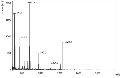
type of impurity, MALDI-TOF-MS was performed for further characterization (Figure
2.1). Two expected charged peaks were displayed at m/z = 1206.3 and 1229.3 (calculated
m/z = 1206.29 and 1229.28), corresponding to the molecular ion peak of compound 1
and [M+Na]+, respectively. If a difunctionalized fullerene was present, peaks at
approximately m/z = 1692.6 and 1715.6 would be expected. Therefore, the absence of
these peaks demonstrated that only mono-alkynyl functionalized fullerene was obtained.
Figure 2.1MALDI-TOF-MS spectrum of compound 1.
In addition, most reactions involving fullerene require a large amount of solvent and
produce relatively low yields because of its poor solubility (around 2.8 mg/mL in toluene
maximum).34 In our current design, the fullerene modification not only grafted a
long alkyl chains which significantly improved the solubility in organic solvents, such as
toluene, methylene chloride and THF. Both solutions of compound 1 and compound 5
in toluene (25 mg/mL) were kept in a refrigerator for one year without precipitation.
2.3.2 RAFT Polymerization involving azido monomer
Azido-containing monomers can be polymerized by living radical polymerization
with controlled molecular weight and narrow polydispersity. A relatively low
temperature (40 °C) was applied to minimize possible side reactions between the azide
and C=C bond of the monomer (AHMA).32 The six-carbon side chains of the resultant
polymer provide relatively long and flexible tethers for the fullerene moieties to
ameliorate the rigidity imposed by the backbone.12 In addition to homopolymer, random
copolymers poly(AHMA-r-MMA) were prepared by adding MMA in the polymerization
to vary the fullerene content along the SFP chains. Thus, both fullerene content and chain
length could be adjusted independently to study the effects of these variables on the
polymer properties.
To demonstrate the controllability of the RAFT copolymerization of AHMA and
MMA, a kinetics study (Figure 2.2) was performed with a fixed feed ratio of AHMA to
MMA (1:20). Figure 2.3a shows a pseudo-first-order kinetics plot indicating a constant
free radical concentration in the polymerization process. The number average molecular
weights (Mn)increased linearly with monomer conversion and were in agreement with
predictions (Figure 2.3b). Moreover, the PDIs were kept below 1.2 with conversions up
to 82%. Generally, the RAFT copolymerization of AHMA and MMA were
well-controlled, and the kinetics were similar to the polymerization of other
azido-functionalized methacrylate monomers which we previously studied.35
Figure 2.3 (a) Kinetics plot and (b) dependence of the molecular weight and polydispersity on the conversion for the RAFT polymerization of AHMA and MMA
(a)
(1:20) ([monomer]: [CPDB]: [V-70] = 300:1:0.1, 40 °C). The solid line represents the theoretical number molecular weights.
Figure 2.4 1H NMR spectrum of prepolymer 2.
The fullerene loading of the SFP’s was adjusted by simply altering the feed ratios of
AHMA to MMA in the syntheses of the prepolymers. Consequently, a series of
prepolymers with variable molecular weights and compositions were synthesized for the
susequent click reactions. Table 2.1shows that the compositions of the prepolymers were
consistent with the feed ratios of the corresponding polymerizations, indicating that
AHMA and MMA have similar relative reactivity ratios in this composition range and
can be randomly copolymerized. The compositions of the prepolymers were determined
by integrated areas of the corresponding peak of each repeat unit in the 1H NMR spectra.
Using prepolymer 2 as an example (Figure 2.4): the methylene protons (next to the
oxygen) of AHMA residue at 3.93 ppm and the methyl protons of MMA residue at 3.59