R E S E A R C H
Open Access
Experimental analysis of PAPR reduction technique
using hybrid peak windowing in LTE system
Dongwan Kim
1,2and Sunshin An
1*Abstract
Orthogonal frequency division multiplexing (OFDM) has the advantages of spectral efficiency in wideband
communication systems such as 3GPP long-term evolution (LTE). However, OFDM suffers from a high peak-to-average power ratio (PAPR). Several schemes, such as peak windowing, clipping and filtering, have been proposed in order to reduce the PAPR in OFDM-based systems. However, these schemes reduce the peak signals regardless of the PAPR pattern; thus, while guaranteeing error vector magnitude (EVM) and adjacent channel leakage ratio (ACLR) performances they do not efficiently reduce the PAPR. In this paper, we propose a hybrid peak-windowing scheme that selects the optimum PAPR reduction scheme according to the PAPR pattern, and we evaluate its performance using a real LTE test bed. Our test results show that the proposed scheme outperforms the existing schemes in terms of EVM, ACLR, and power consumption.
Keywords:PAPR; CFR; Clipping and filtering; Peak windowing; Power consumption; LTE
1 Introduction
With the increasing demand for high data rate wireless communications, 3GPP long-term evolution (LTE) has become one of the dominant wireless access technolo-gies. LTE is expected to result in significantly improved transmission rates and spectral efficiency compared to 3G systems such as wide code division multiple access (WCDMA). To enable better performance, the LTE standard adopts orthogonal frequency division multiplex-ing (OFDM), which is a transmission method employed for wideband communications because of its high spectral effi-ciency, robustness to inter-symbol interference (ISI), and simple receiver structure [1].
However, one of the major drawbacks of OFDM-based systems is the high peak-to-average-power ratio (PAPR) problem that is due to the summing of sub-carrier sig-nals. The high PAPR signals over the dynamic range of a power amplifier (PA) and digital-to-analog converter (DAC) lead to non-linear distortions such as the spectral regrowth phenomena, in-band noise, and increased quantization errors. These results cause degradations in
the adjacent channel leakage ratio (ACLR) and error vector magnitude (EVM) performance [2].
Several methods have been proposed to reduce PAPR in OFDM-based systems. Single-carrier frequency division multiple access (SC-FDMA) is a variant of OFDM-based systems in which the data symbols of each user are first modulated in the time domain and then discrete Fourier transform (DFT) spread across the data subcarriers to yield a signal that is commensurate with single-carrier modulation. Hence, in the absence of multiple superim-posed subcarriers, the envelope fluctuations are less pro-nounced and the power efficiency is higher than for conventional OFDM-based systems. In addition, the most straightforward solution for alleviating the side effects of high PAPR is to guarantee sufficient headroom for the sig-nal with the highest peak to be processed in the dynamic range. However, a large amount of headroom results in a significant reduction in power efficiency. Therefore, an at-tractive and cost-effective solution is to reduce the PAPR of the OFDM signal.
To reduce the high PAPR in OFDM, a number of ap-proaches have been proposed. The existing solutions are broadly classified into two categories: receiver-dependent schemes and receiver-independent schemes. Receiver-dependent schemes transmit a PAPR reduction signal in-cluding additional information. At the receiver side, the
* Correspondence:[email protected] 1
The School of Electrical Engineering, Korea University, Anam-dong, Seongbuk-Gu, Seoul 136-701, South Korea
Full list of author information is available at the end of the article
transmitted signal can be decoded using the additional in-formation. Typically, the tone reservation (TR) [3], selective mapping (SLM) [4], and partial transmit sequence (PTS) [5] are receiver-dependent schemes. However, the inclusion of additional information in receiver-dependent schemes will cause a reduction in the data rate. Furthermore, to en-able the use of additional information, the receiver struc-ture should be modified to restore the PAPR reduction signals.
In contrast, receiver-independent schemes transmit a PAPR reduction signal without any additional informa-tion. The clipping and filtering (CAF) schemes [6,7] and the peak windowing (PW) schemes [8,9] are fam-ous independent schemes. Because receiver-independent schemes operate only on the transmitter side, the schemes do not require any modification of the receiver structure and do not cause any reduction in data rate because of the absence of additional infor-mation. Thus, receiver-independent schemes are widely used in practice because of their convenience. However, in [6-9], it is seen that the original signals become dis-torted and there are degradations in the performance of certain parameters such as the ACLR and EVM because the receiver cannot know the distorted information. In [7], experimental results for the relationship between the average power, EVM, and ACLR for an OFDM-based system with CAF are presented. The CAF scheme is a simple and effective scheme that is used to reduce the PAPR; however, it still leads to performance degrad-ation of the EVM and ACLR because of the peak regen-eration phenomenon caused by its filtering opregen-eration. Another solution is the PW scheme, which can effi-ciently reduce high-PAPR signals compared to the CAF scheme. However, the PW scheme still cannot effi-ciently eliminate successive high-PAPR signals. In [8], weighting factors for each peak are obtained by solving matrix-based linear equations so that the overall win-dow function reduces each peak to the clipping thresh-old. In [9], sequential asymmetric suppression peak windowing and weighted windowing were proposed. While both schemes can deal with successive peaks that may cause excessive attenuation or spectral regrowth in the PW scheme, [8,9] focus on eliminating successive peak signals, and therefore, they cannot be efficiently applied to other cases such as discontinuous peak signals.
In this paper, we propose a new PAPR reduction scheme called hybrid peak windowing (HPW). The pro-posed scheme minimizes the degradation of the ACLR and EVM performance by selecting the proper PAPR re-duction scheme as the input signal PAPR pattern. By ap-plying the proposed scheme, we can optimally eliminate high-PAPR signals while minimizing performance deg-radation. In addition, we evaluate the proposed scheme
relative to the existing PAPR reduction schemes using a real LTE system test bed and prove that the proposed scheme exhibits better performance than the existing schemes.
The rest of this paper is organized as follows. In Sec-tion 2, we discuss the PAPR issue in LTE systems and the related LTE specifications. In Section 3, we introduce the existing PAPR reduction schemes and the proposed scheme. In Section 4, we present a performance analysis, and we conclude the paper in Section 5.
2 PAPR issue in LTE systems
2.1 Characteristics of OFDM signals
The complex baseband OFDM signal withNsubcarriers
is expressed as:
whereXkis the complex modulated data symbol on
sub-carrier k from a given binary phase-shift keying (BPSK)
or M-ary quadrature amplitude modulation (M-QAM) constellation. The frequency spacing,Δf, which is chosen to maintain the orthogonality of subcarrier frequencies, is usually assumed to be 1/T. Samples of x(t) at t = nT/
NQ, where Q is the oversampling factor, can be
effi-ciently computed via the inverse discrete Fourier
trans-form (IDFT) as X ¼ X0;⋯;XN
2−1;0;X−1;⋯;X−N2
h i
.
WhenNis large, the time signal,x(t), exhibits a Gaussian distribution because the central limit theorem applies.
The OFDM signal is the sum of many independent signals modulated into sub-carriers of equal bandwidth, so it has a high peak-signal distribution compared to a single-carrier system such as WCDMA. The fluctuations can be characterized as a PAPR, which can be discretely approximated as:
Where xn is the signal samples in the time domain.
High-PAPR signals lead to a critical hardware implemen-tation issue. For example, when large peak signals
amongxnare processed out of the input dynamic range,
it will result in non-linear distortions and decreased power efficiency of the PA. Therefore, high-PAPR values need to be reduced to improve power efficiency while minimizing non-linear distortion. However, there may be additional non-linear distortion because of intentional reductions of the PAPR.
(PAPR = CF2). To measure the value of the CF, a com-plementary cumulative distribution function (CCDF) is used. The CCDF curve is characterized by the probabil-ity of exceeding a particular signal level with respect to the average power. In addition, we use a design criterion that is 0.001% of the CCDF value because that is a typ-ical design constraint in practtyp-ical communication hard-ware designs. In other words, we assume that signals whose probabilities are below 0.001% do not affect sys-tem performance because they rarely occur.
2.2 EVM and ACLR in the LTE standard
The performances of the EVM and ACLR are directly related to the PAPR reduction scheme. Before discussing PAPR reduction schemes, we first introduce the EVM and ACLR.
The EVM is defined as the ratio of the power of the error vector to the root mean square (RMS) power of the reference, and is represented as:
EVMð Þ ¼%
wherePerror is the RMS power of the error vector and
Preference is the power of the reference vector. In gen-eral, Preference is the original signal, x(n). The EVM is closely related to the bit error rate (BER) and modula-tion error ratio, which is the ratio of the mean signal power to the mean error power. That is, a certain EVM level should be guaranteed to minimize the BER per-formance. In this paper, the EVM represents the degree of degradation of the modulation signal.
Out-of-band (OOB) radiation refers to unwanted radi-ation immediately outside the nominal channel resulting from the modulation process and non-linearity in the transmitter, excluding spurious radiation. The OOB radi-ation limit is specified in terms of a spectrum emission mask and the ACLR performance. The ACLR is defined as the ratio of the transmitted power to the power mea-sured after a receiver filter in the adjacent channel, and is expressed as:
where Bis the range of frequencies in the transmission
channel, Badjis the range of frequencies in the adjacent
channel, and Sy is the power spectral density of the re-ceived signal. In addition, the ACLR should not exceed a certain threshold value because the OOB radiation can affect other channels as noise.
When the original signals are distorted intentionally to reduce peak signal components, the performance in terms of the EVM and ACLR will be degraded. Thus,
the LTE standard defines the minimum requirements for the performance of the EVM and ACLR because they are critical metrics to guarantee system performance. The LTE standard defines technical specification (TS) 36.104 [10] and TS 36.141 [11] for the LTE system per-formance test. TS 36.104 establishes the minimum radio frequency (RF) characteristics and minimum perform-ance requirements of the evolved universal terrestrial radio access (E-UTRA) base station (BS), and TS 36.141 establishes the RF test methods and conformance re-quirements for the E-UTRA BS. The minimum require-ments given in TS 36.104 make no allowance for measurement uncertainty. In contrast, TS 36.141 defines test tolerances that are individually calculated for each test. However, TS 36.104 is used more broadly in LTE system performance evaluations because of its strict lim-itations, even though TS 36.141 is defined for RF test methods. Thus, in this paper, we use TS 36.104 for per-formance evaluation.
As described above, PAPR reduction schemes affect the EVM and ACLR performance. In TS 36.104 and TS 36.141, the related test specification for the EVM and ACLR are specified as the E-UTRA test model (E-TM) 1.1, E-TM 1.2, E-TM 2, E-TM 3.1, E-TM 3.2, and E-TM 3.3. E-TM 1.1 and E-TM 1.2 are related to the perform-ance of the ACLR, and the measured value should be higher than the TM specification. Further, TM 2, E-TM 3.1, E-E-TM 3.2, and E-E-TM 3.3 are related to the per-formance of the EVM, and the measured value should be lower than the E-TM specification. The test purpose and specifications of the E-TMs are summarized in Table 1.
3 Proposed hybrid peak windowing scheme The CAF scheme is the simplest scheme that is used for re-ducing peak signals. The CAF scheme is composed of a hard clipping procedure and a low-pass filtering (LPF) pro-cedure. In hard clipping processing, the signals over a clip-ping threshold (Th) are eliminated, which is helpful for reducing the PAPR. However, this procedure generates sharp corners in the time domain. That is, the ACLR
Table 1 Purpose of test and specification of E-TM
E-TM Test purpose Specification (10 MHz) [10]
E-TM 1.1 ACLR 45 dBc
E-TM 1.2 ACLR 45 dBc
E-TM 2 64QAM (at min. power) 8%
E-TM 3.1 64QAM (at max. power) 8%
E-TM 3.2 QPSK 17.5%
16QAM 12.5%
E-TM 3.3 QPSK 17.5%
performance is degraded because the high-frequency noise components increase. To improve the ACLR performance, the CAF scheme passes the hard clipping output to an LPF. After processing with the LPF, high-frequency noise com-ponents are eliminated, and the CAF scheme realizes an improved ACLR performance. However, the CAF scheme generates a peak regeneration phenomenon, which is caused by the LPF operation after a hard clipping proced-ure. Thus, when we use the CAF scheme, we should set a lower clipping threshold than the target PAPR considering the peak regeneration phenomenon. Because of the lower clipping threshold relative to the target PAPR, the existing intentional signal distortion will be deteriorated and it will
degrade the EVM performance. The CAF output, xcaf, is
written as:
xcafð Þ ¼n fx nð Þ⋅wcð Þn g hLPFð Þn ð5Þ
wherex(n) is the original input signal of the CAF scheme,
hLPF(n) is the impulse response of the LPF used to
elimin-ate OOB radiation, * is the convolution operator, andwc(n) is the hard clipping window function expressed as:
wcð Þ ¼n
The PW scheme multiplies peak signals with a specific window function in the presence of a peak signal. By multiplying a continuous window function, the PW scheme mitigates the performance degradation com-pared to the CAF scheme. In order to prevent OOB ra-diation, the PW scheme can control the window length
L. However, increasing L can lead to degradation of the EVM performance because of the overlapping of the specific window function, which generates an abnormal peak cancellation window. The PW scheme is modeled as:
symmetric window function, and ni is the peak sample
index whose value is defined as:
x nið Þ
j j ¼ max
ni−≤n≤niþjx nð Þj ð9Þ
whereniis the non-uniformly spaced sample index
run-ning over the specific set of samples, which exceeds the threshold Th. Further, ni-represents a sample index on the rising edge of the signal, where it first exceeds the
threshold Th, whileni+represents a sample index, where the signal peak dips below the threshold Th. The win-dow functions can be cosine, Hamming, Hanning, or Kaiser windows. The Kaiser window function is com-monly used because it is simple to shape the spectrum
by changing window length L and the shape factor β.
Here, we considered Kaiser window with length of 31 taps andβis 5.
As described previously, to alleviate the peak regener-ation phenomenon, the CAF scheme should set up a clip-ping threshold that is lower than the target PAPR level. Thus, the CAF scheme generates excessive degradation of the EVM performance. However, the CAF scheme elimi-nates peak signals with a fixed signal loss regardless of whether successive peak signals occur. In addition, the PW scheme eliminates peak signals smoothly by multiplying them by a specific window function. However, when the consecutive peak signals occur within half of the window length in the PW scheme, the window function can over-lap. This leads to unintended distortions of the original sig-nals and generates unintended distortion sigsig-nals, even if the signal is under the clipping threshold. However, the PW scheme is usually preferred to the PAPR reduction scheme because it results in reduced performance degrad-ation compared to the CAF scheme. In summary, using the same clipping threshold as the PW scheme, the CAF scheme cannot eliminate high-PAPR signals entirely be-cause of the peak regeneration phenomenon. Furthermore, the PW scheme can deteriorate signal distortion in the case of successive peak signals.
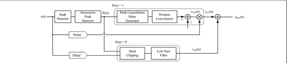
To prevent unintended distortions, we propose a HPW scheme, which aims to determine the peak signal over the clipping threshold level and to suppress it while minimizing unintended distortion. The main goal of the HPW scheme is to select a proper PAPR reduction scheme as a peak sig-nal pattern. When the single peak sigsig-nal is detected in the half window length, the HPW scheme eliminates the peak signal using the PW scheme. However, when successive peak signals are detected within a half of the window length, the HPW scheme eliminates consecutive peak sig-nals using the CAF scheme, and not the PW scheme. In addition, in the proposed scheme, an even-order filter struc-ture is used to minimize peak regeneration that occurs dur-ing the filterdur-ing operation, and the delay between the PW scheme and the CAF scheme is designed to be the same.
When the original signals enter the HPW scheme, the peak detector first checks the peak signals above the clipping threshold. Then, the successive peak detector monitors whether or not the distance from the previous peak is less than half of the window length. If successive peak signals are detected within half of the window length, the successive peak detector sets the enabled sig-nal to zero. Next, the HPW scheme processes the CAF scheme to prevent unintended excessive distortion. However, if successive peak signals are not detected within half of the window length, the enabled signal is set to one, and the HPW scheme processes the PW scheme, and not the CAF scheme. Thus, the correct PAPR reduction scheme is selected for the peak signal distribution. The output of the HPW scheme is modeled as:
xhpwð Þ ¼n f1−E nð Þg⋅xcafð Þ þn E nð Þ⋅xpwð Þn ð10Þ
whereE(n) is the output of the successive peak detector. 4 Performance analysis
In this section, we compare the CCDF, ACLR, and EVM performance for the CAF scheme [7], PW scheme [8], and proposed HPW scheme. In the test bed for the per-formance evaluation, LTE test model streams that com-ply with the LTE standard specification are generated. The binary information bit streams are mapped to com-plex BPSK and M-QAM symbols. The output of the mapper is converted from serial to parallel and is proc-essed using a 1024-point complex inverse fast Fourier transform (IFFT). The 1024-point complex-valued time-domain signals are followed by a guard interval (GI). After that, the outputs of the baseband test-model sig-nals are processed by a digital transceiver board, and the output signals of the digital transceiver are processed by a DAC. The output signals of the DAC are up-converted by a local oscillator (LO), and those signals enter a lat-erally diffused metal-oxide semiconductor (LDMOS) PA. The final RF signals are decoded by performing signal analyzer measurements. In the performance evaluation, the system bandwidth is 10 MHz and the RF center
frequency is 2.125 GHz. The PAPR reduction function is embedded in a digital transceiver board and imple-mented in a field-programmable gate array (FPGA). In addition, the input dynamic range of the PA is designed with a 6.5-dB PAPR level. Thus, the output PAPR of the PAPR reduction function is limited to 6.5 dB.
After PAPR reduction processing, the signal power level is adjusted. The peak signals have changing signal amplitudes due to intentional peak signal reduction, so the output of the PAPR reduction function is adjusted by a digital gain block (DGB). In addition, the input dy-namic range of the DAC is maintained at a 6.5-dB PAPR signal level. The output power of the DAC is designed
to be −10 dBm, and the output power of the PA is
de-signed to be 46 dBm. Figure 2 depicts a block diagram of the LTE test bed employed for the performance evaluation.
First, we compared the FPGA resources of the HPW with those of the existing schemes in Table 2. In the im-plementation, we used Xilinx FPGA (XC7Z100; Xilinx Inc., San Jose, CA, USA), and the clock speed was 245.76 MHz.
As shown in Table 2, the CAF requires the smallest amount of FPGA resources, and more resources are re-quired by PW and HPW when compared with those used by the CAF scheme. Unfortunately, because of its imple-mentation complexity, the HPW scheme requires the most FPGA resources. As a result, the FPGA power consump-tion of HPW is the largest of the three schemes. However, compared with other schemes, the HPW scheme is char-acterized by the lowest PAPR while meeting the EVM and ACLR requirements; therefore, the PA power con-sumption of HPW will be the lowest. In the HPW scheme, the power consumed by the total system is re-duced because of the power reduction of the PA despite the fact that the power consumed by the FPGA has in-creased. This will be discussed in detail at the end of this section.
The main goal of the PAPR reduction scheme is to in-crease the efficiency of the PA by limiting the peak sig-nal level. Thus, the origisig-nal CCDF without the PAPR reduction schemes is first measured to verify the original
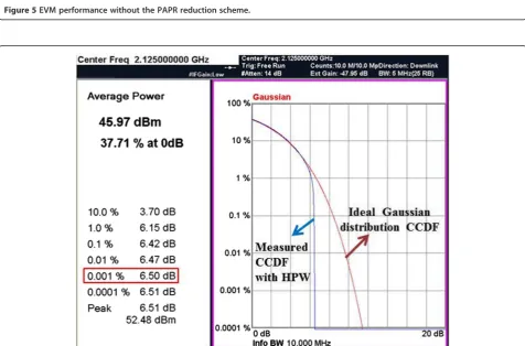
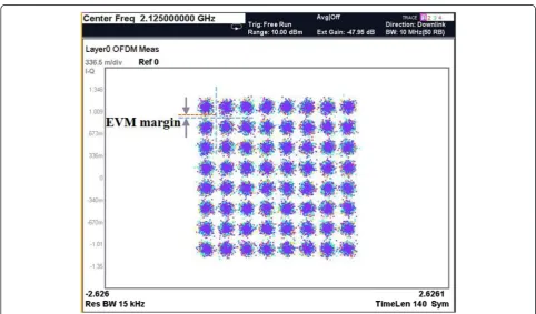
PAPR level. Figure 3 depicts the original CCDF without the PAPR reduction functions. As seen in Figure 3, the original CCDF value at 0.001% is 10.40 dB, and the ori-ginal CCDF has a trend similar to a Gaussian distribu-tion. The original CCDF value is measured at the DAC output to exclude the effects of the PA non-linear distor-tion. As seen in Figure 3, the original CCDF cannot sat-isfy the input dynamic range of the PA because the design constraint of the PA is a 6.5-dB PAPR. Conse-quently, it will degrade the ACLR and EVM performance because of the non-linear distortion of the PA and other active components. Thus, peak signals with PAPR values exceeding 6.5 dB should be eliminated to guarantee the in-put dynamic range of the PA. Figure 4 represents the deg-radation of the ACLR performance without the PAPR reduction scheme due to non-linear distortion. In Figure 4, we can verify that the value of the ACLR is 38.1 dBc. Thus, for this hardware design constraint, the ACLR performance cannot satisfy the LTE test specification without the PAPR reduction scheme because of the non-linear distortion of active components, especially the PA. In addition, Figure 5 represents the EVM performance of E-TM 3.1 without the PAPR reduction scheme. The value of the EVM is 2% and is caused by non-linear distortion of the DAC and PA. This error value contains other noise factors such as phase-locked loop (PLL) jitter noise and time-synchronous error. However, the EVM performance still satisfies the LTE test specification even though the non-linear in-band noise and inherent transceiver noise degrade the EVM performance.
As described above, the design constraint of the PA is set to a 6.5-dB input dynamic range. Thus, peak signals above the 6.5-dB PAPR level are eliminated by the HPW
scheme, and the desired CCDF is obtained, as shown in Figure 6. The value of the CCDF at 0.001% is 6.5 dB, so the input dynamic range of the PA satisfies our design metric with the HPW scheme. After applying the HPW scheme, the ACLR and EVM performance that satisfied the LTE test specification are shown in Figures 7 and 8, respectively. As seen in Figure 7, an ACLR performance value of 63.6 dBc is obtained, which satisfies E-TM 1.1. The improved result is because of the reduced PAPR level achieved by the HPW scheme, which implies that the non-linear distortion components are eliminated by the HPW scheme. In addition, an EVM performance value of 5.8% for E-TM 3.1 is obtained, as shown in Figure 8. That is, both the inherent system noise and intentional dis-tortion by the HPW scheme degrade the EVM perform-ance. However, the EVM performance for the HPW scheme still satisfies the E-TM 3.1 specification. In particu-lar, the E-TM 3.1 test specification applies to most high-degree modulation schemes such as 64 QAM at maximum power, and this specification is regarded as the strictest and one of the most important specifications of all the EVM test specifications.
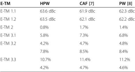
The proposed HPW scheme is compared with the CAF [7] and PW [8] schemes. Table 3 summarizes the performance comparison between the proposed HPW scheme and the existing schemes. As seen in Table 3, the HPW scheme outperforms the CAF and PW schemes in all E-TMs in terms of the EVM and ACLR performance. As described above, both the CAF and PW schemes eliminate the PAPR component regardless of the PAPR signal pattern, which may lead to excessive intentional distortion.
In particular, we verify the differences in EVM perform-ance between the HPW scheme and the existing schemes. We also check the difference in the performance according to E-TM 3.2 and E-TM 3.3, even though they have the same modulation scheme. Because the PAPR pattern in each E-TM is different, the side effects of a PAPR reduction scheme such as EVM degradation will be different for each E-TM. We then verified that the HPW scheme minimizes the side effects of intentional signal distortion by selecting
Figure 2Test block diagram.
Table 2 FPGA resources comparison between HPW and existing schemes
Flip flop
Look up table Memory DSP48
Logic Shift register (36 kbit) (25 × 18)
CAF 2,012 328 54 8 21
PW 10,512 7,341 74 72 46
Figure 3CCDF of the original LTE test model signal.
Figure 5EVM performance without the PAPR reduction scheme.
Figure 7ACLR performance with the HPW scheme.
the proper PAPR reduction scheme for the peak signal dis-tribution for all of the E-TMs.
As shown in Tables 1 and 3, the ACLR performance still has a large margin to the specification requirements com-pared to that of EVM. Therefore, because the critical side effect is EVM, which resulted in degraded performances with the PAPR reduction scheme, we measured the amount by which the EVM degraded with the PAPR reduction level, while still meeting the ACLR requirements. When verifying the minimum PAPR level while satisfying the crit-ical EVM specification, we can reduce the PAPR level to 5.82 dB using the HPW scheme. However, when we use the CAF scheme and PW scheme at a 5.82 dB PAPR level, we obtain EVM performance values of 10.24% and 9.81%, which do not satisfy E-TM 3.1.
Figure 9 depicts the results of the EVM performance for HPW, PW, and CAF schemes using the PAPR value while satisfying the ACLR specification. As seen in Figure 9, the HPW scheme always outperforms PW and CAF schemes for the same PAPR value. We also conducted a test to ver-ify the minimum PAPR level while satisfying EVM stan-dards. As seen in Figure 9, the HPW, PW, and CAF schemes can reduce the PAPR level to 5.82, 6.25, and 6.38
dB, respectively, while satisfying the LTE standards. This means that when we use HPW, we can reduce PAPR to as low as 5.82 dB, enabling us to design a more energy-efficient PA. The relation between the energy efficiency of the PA and the input PAPR is given in Equation 11, which is derived from reference [12]:
η¼G expð−gPAPRiÞ ð11Þ
where the efficiency, η, is in [%] and the PAPRi is in [dB].Gandgare 90.7% and 0.1202, respectively, and in-dicate the ideal peak efficiency and slope of the PA’s effi-ciency, respectively. Therefore, the HPW scheme can reduce the power consumption of a PA by much lower than other schemes by controlling the drain voltage of the PA based on the possible reduction level of the PAPR. Consequently, the HPW scheme enhances the PA efficiency by 2.27% and 2.93% when compared to the PW and CAF schemes, respectively. The PA ac-counts for a large proportion of the power consumption in the overall communication system [13], and reducing the power consumption of a PA is one of the most effi-cient schemes in the implementation of low-power communication systems. As described in Table 2, even though HPW increases the power consumption of the FPGA because of its implementation complexity, HPW can further reduce the power consumption of a PA de-pending on its low PAPR characteristics. This leads to
Table 3 Performance comparison for E-TM at 6.5-dB PAPR
E-TM HPW CAF [7] PW [8]
E-TM 1.1 63.6 dBc 61.9 dBc 62.3 dBc
E-TM 1.2 63.5 dBc 62.1 dBc 62.2 dBc
E-TM 2 0.8% 1.7% 1.4%
E-TM 3.1 5.8% 7.3% 6.8%
E-TM 3.2 4.2% 4.7% 4.8%
7.8% 8.5% 8.4%
E-TM 3.3 10.7% 11.4% 11.2%
4.2% 4.7% 4.6%
Figure 9EVM performances vs. PAPR.
Table 4 Power consumption comparison
HPW PW CAF
Digital transceiver 31.12 31 30.81
(FPGA) (15.02) (14.9) (14.71)
PA 132.72 137.31 138.59
an overall power reduction in the communication system. The experimental results for the power consumption are summarized in Table 4, which shows that the HPW scheme is responsible for the largest power consumption in digital transceivers because of increasing FPGA power. However, the HPW scheme has the lowest power consumption in PAs, and its total power is reduced by 5.87 and 4.59 W when compared to the CAF and PW schemes, respectively.
5 Conclusions
In this paper, we proposed a new HPW scheme for OFDM systems. With the proposed HPW scheme, we realized im-proved performance by selecting a suitable PAPR reduction scheme for the signal amplitude distribution. Even though the performance in terms of the CCDF, EVM, and ACLR are related to many other hardware component character-istics as design metrics, we have demonstrated that the proposed HPW scheme outperforms the CAF and PW schemes. This was achieved using a real LTE system test bed. We also demonstrated that the power consumption could be reduced by the proposed HPW scheme. Because the HPW scheme has the smallest PAPR level compared to others, while still meeting the LTE standard requirements, there was a power reduction of the PA depending on the minimum PAPR. Even though the power consumption of the FPGA resources had increased, the power efficiency of the overall communication system increases because the power reduction of PA is much greater.
Competing interests
The authors declare that they have no competing interests.
Acknowledgements
This work was supported partially by the National Research Foundation (NRF) of Korea grant funded by the Korea government (MEST)
(no. NRF2012K1A3A1-A09026959).
Author details
1
The School of Electrical Engineering, Korea University, Anam-dong, Seongbuk-Gu, Seoul 136-701, South Korea.2Samsung Electronics Co., Ltd., Suwon-si, Gyeonggi-do 443-742, South Korea.
Received: 27 October 2014 Accepted: 9 February 2015
References
1. 3GPP TR 36.913, Requirements for further advancements for Evolved Universal Terrestrial Radio Access (E-UTRA), v.8.0.1, March 2009. 2. E Costa, M Midrio, S Pupolin, Impact of amplifier nonlinearities on OFDM
transmission system performance. IEEE Commun Lett3, 37–9 (1999) 3. J Tellado,Peak to average power reduction for multicarrier modulation, Ph.D.
dissertation, Stanford Univ, 2000
4. RW Bäuml, RFH Fisher, JB Huber, Reducing the peak-to-average power ratio of multicarrier modulation by selected mapping. Elect Lett32(22), 2056–7 (1996)
5. SH Müller, JB Huber, OFDM with reduced peak-to-average power ratio by optimum combination of partial transmit sequences. Elect Lett33(5), 368–9 (1997)
6. X Li, LJ Cimini Jr, Effects of clipping and filtering on the performance of OFDM. IEEE Comm Lett2, 131–3 (1998)
7. T Lee, H Ochiai, Experimental analysis of clipping and filtering effects on OFDM systems, inProc. of the 2010 IEEE Int. Conf. on Commun. (ICC 2010)
(South Africa, Cape Town, 2010)
8. S Cha, M Park, S Lee, K-J Bang, D Hong, A new PAPR reduction technique for OFDM systems using advanced peak windowing method. IEEE Trans Consum Electron54(2), 405–10 (2008)
9. G Chen, R Ansaru, Y Yao, Improved peak windowing for PAPR reduction in OFDM, inIEEE 69th VTC Spring, 2009, pp. 1–5
10. 3GPP specification 36.104, http://www.3gpp.org/DynaReport/36104.htm 11. 3GPP specification 36.141, http://www.3gpp.org/DynaReport/36141.htm 12. D Wulich, Definition of efficient PAPR in OFDM. IEEE Commun Lett9, 832–4
(2005)
13. Z Hasan, H Boostanimehr, VK Bhargava, Green cellular networks: a survey, some research issues and challenges. IEEE Commun Surv Tuts13(4), 524–40 (2011). Fourth Quarter
Submit your manuscript to a
journal and benefi t from:
7 Convenient online submission 7 Rigorous peer review
7 Immediate publication on acceptance 7 Open access: articles freely available online 7 High visibility within the fi eld
7 Retaining the copyright to your article