An Enhanced Forward-Looking SAR Imaging Algorithm
Based on Compressive Sensing
Bo Pang, Hao Wu*, Shiqi Xing, Dahai Dai, Yongzhen Li, and Xuesong Wang
Abstract—Having the imaging ability of the area in front of flight direction, forward-looking synthetic aperture radar (SAR) has become a hot topic in areas of SAR research. Nevertheless, constrained by limited azimuth aperture length, the imaging of forward-looking SAR suffers from poor azimuth resolution. Aiming at this problem, an enhanced forward-looking SAR imaging algorithm is proposed in this paper. This algorithm takes both super-resolving ability and computational burden into account. Firstly, an imaging framework is proposed to decrease the computational burden. Secondly, an iterative regularization implementation of compressive sensing (CS) is proposed to improve azimuth resolution. Finally, imaging experiments based on simulated data and Ku-band complex valued image data from the MiniSAR system demonstrate the effectiveness of the proposed algorithm.
1. INTRODUCTION
By interrogating a scene with pulses from diverse angles, synthetic aperture radar (SAR) is able to produce its high-resolution images. Having the ability to operate at night and under all-weather circumstances, SAR has become one of the most promising research tool for remote sensing applications such as forestry, agriculture, geology, and military reconnaissance in recent years. However, because of poor doppler resolution and azimuth ambiguities, conventional SAR is not applicable with respect to the forward-looking direction, which hinders its application.
In early 1990s, the concept of forward-looking radar was firstly proposed by Witte [1, 2]. By replacing the virtual antennas in SAR with a set of physically existent antenna elements distributed in space and switching the elements sequentially [1], the forward-looking radar could eliminate the visualization gap with respect to the forward direction of the flight path by a coherent processing of the radar echoes similar to a conventional SAR system [3]. Therefore, in many articles, this kind of forward-looking radar is also called forward-forward-looking SAR [4–10]. With the ability to provide two-dimensional [4– 7] and three-dimensional images [8–10] of the earth ground in front of the platform, forward-looking SAR becomes more and more attractive to industrial and academic communities. During the last decades, some progresses about forward-looking SAR have been made. The most representative one is the system named sector imaging radar for enhanced vision (SIREV) which was developed by German Aerospace Center [11].
For the two-dimensional imaging algorithm of forward-looking SAR, the matched filter (MF) based algorithms are always utilized. For instance, in [12], the extended chirp scaling (ECS) algorithm is adopted. The ECS algorithm enables effective imaging for forward-looking SAR by combining the operations of “spectral analysis” (SPECAN) and “azimuth scaling”. However, its computational load is very high. Next, by taking the untreated phase in the ECS algorithm into account and using the
Received 5 November 2018, Accepted 14 December 2018, Scheduled 23 January 2019 * Corresponding author: Hao Wu ([email protected]).
azimuth processing technique of ScanSAR as a reference, a revised chirp scaling algorithm for forward-looking SAR is proposed in [7]. This algorithm is computationally more efficient than ECS. [13] and [14] propose two algorithms which are suitable for high velocity platform based on the idea of range Doppler (RD) and Doppler beam sharpening (DBS), respectively. Taking acceleration into account, [15] proposes a chirp scaling algorithm for forward-looking SAR with constant acceleration. Although they are easy to implement, these MF based algorithms suffer from poor azimuth resolutions due to limited azimuth aperture, which hinders the applications of forward-looking SAR.
In order to improve azimuth resolutions of forward-looking radar system, some approaches such as deconvolution algorithms and bistatic SAR have been proposed. However, for bistatic SAR, it is difficult to implement in practice due to synchronization problem, large range cell migration (RCM), and complicated structure [16–18]. For deconvolution, it is essentially a highly ill-posed problem which is sensitive to noise and hardly ensures a robust solution [19, 20].
As a burgeoning technique, compressive sensing (CS) has brought about a breakthrough to the reconstruction of sparse signal. According to this theory, the exact reconstruction of an unknown sparse signal can be obtained from limited measurements by solving a sparsity-constrained optimization problem [21]. Furthermore, the super-resolving ability of CS could contribute to overcome the limitation induced by synthetic aperture and bandwidth [22]. Now CS has been discussed and explored in different areas. In [23], a new radar system which can eliminate the need for the matched filter in the radar receiver and reduce the required analog-to-digital (AD) conversion bandwidth is designed based on the CS theory. For wide-angle imaging, where the assumption of isotropic point scattering does not hold up, the CS theory is utilized to enhance the resolution [24, 25]. In [26, 27], the CS theory is applied to ground penetrating radar (GPR) imaging. As a result, sparser and sharper target images are acquired by using only a small subset of the measurements. In tomographic SAR (Tomo-SAR) area, the CS theory provides a reliable solution for the aliasing effect and poor resolution brought by nonuniform inter-track distance and limited overall baseline. Consequently, the height scattering profile of man-made objects such as stadiums and buildings are better reconstructed [22, 28]. For SAR imaging, especially when the imaging of man-made structures is considered, the scattered signal can be well approximated as a sum of responses from a limited number of strong scattering centers. As a result, the sparsity condition is well satisfied [29], which provides a foundation for exploring the CS theory in SAR imaging.
In this paper, the CS theory is exploited to improve the azimuth resolution of forward-looking SAR. The rest of the paper is organized as follows. In Section 2, the signal model of forward-looking SAR is established. Based on this signal model, Section 3 is dedicated to presenting the enhanced imaging algorithm for forward-looking SAR. In Section 4, imaging experiments based on simulated data and Ku-band complex valued image data from the MiniSAR system demonstrate the effectiveness of the proposed method. The images reconstructed by the proposed method are also compared with images generated by the RD algorithm [13], as it is classical and is often used by the radar imaging community for comparison and verification of imaging algorithms. Finally, conclusions are presented in Section 5.
2. SIGNAL MODEL OF FORWARD-LOOKING SAR
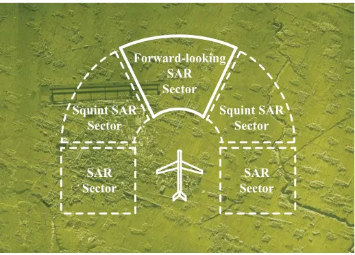
Figure 1 shows the imaging sectors of SAR, Squint SAR and forward-looking SAR. The differences between them can be easily distinguished. As shown in Figure 1, forward-looking SAR fills the visualization gap of SAR and squint SAR with respect to the direction in front of radar movement. Figure 2 illustrates the imaging geometry of forward-looking SAR. The plane flies along x axis (i.e., ground range direction) with velocity v at heighth. The direction along the wing of plane is defined as y axis (i.e., azimuth direction). The direction perpendicular toxoy plane is defined asz axis.
Forward-looking SAR consists of a linear array of antennas which uniformly distribute alongyaxis. During the flight, these antennas sequentially transmit LFM signal with high pulse repetition frequency (PRF) and receive the backscattered signal. The switch frequency is the same as PRF. Assuming that the distance between adjacent antennas is d, the length of the antenna array is L. Consequently, the position of the currently working antenna can be derived as (vt,−L/2 +vat, h). For a point scatterer situated at (x, y,0), the travel path of radar signal can be expressed as
R(t) = 2
Squint SAR Sector
SAR Sector Squint SAR
Sector
SAR Sector
Forward-looking SAR Sector
Figure 1. Imaging sector of forward-looking SAR. Figure 2. Imaging geometry of forward-looking SAR.
where tstands for the slow time; vt is the x position of the currently working antenna;−L/2 +vatis the y position of the currently working antenna; va = d·P RF is the equivalent velocity in azimuth direction.
Assume that the LFM signal transmitted by radar is
si(τ, t) = rect (τ) expj2πf0τ+jπKτ2
(2) where τ denotes the range time; K stands for the chirp rate; f0 is the carrier frequency. The corresponding range and azimuth “Fourier” resolutions of forward-looking SAR can be expressed as
ρr = c
2B (3)
ρa = λL 2R0
(4)
wherec denotes the speed of light, andB denotes signal bandwidth.
When signal shown in Eq. (2) is transmitted, the baseband signal backscattered by the target situated at (x, y) can be written as
s0(τ, t;x, y) =g(x, y) rect
τ −R(t;x, y) c
·exp
jπK
τ−R(t;x, y) c
2
exp
−j2πR(t;x, y) λ
(5) where g(x, y) stands for the complex reflectivity of the target situated at (x, y). Nevertheless, for a scene composed of many targets, the received signal should be expressed as the superposition of the scattering components from all targets which are illuminated by the radar’s beam. Consequently, the received signal has the form
s0(τ, t) =
G
s0(τ, t;x, y)dxdy (6)
By far, the model of the baseband signal received by forward-looking SAR has been derived. Then the task of image formation is to decode g(x, y) from the received signals0(τ, t).
3. IMAGING ALGORITHM IMPLEMENTATION
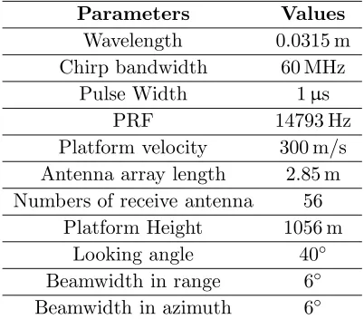
Table 1. Simulation parameters.
Parameters Values
Wavelength 0.0315 m
Chirp bandwidth 60 MHz
Pulse Width 1µs
PRF 14793 Hz
Platform velocity 300 m/s Antenna array length 2.85 m Numbers of receive antenna 56
Platform Height 1056 m
Looking angle 40◦
Beamwidth in range 6◦ Beamwidth in azimuth 6◦
parameters listed in Table 1 are adopted, the azimuth resolution (7.62 m) is much worse than the range resolution (2.5 m). Furthermore, while the range resolution can be improved by increasing signal bandwidth, the azimuth resolution is severely constrained by the size of the platform itself. Therefore, an enhanced forward-looking SAR imaging algorithm based on CS is proposed in this section. This algorithm takes both the super-resolving ability and the computational burden into account and produces satisfying results. The derivation of this algorithm is summarized as follows.
3.1. Imaging Framework
When the enhanced forward-looking SAR imaging algorithm based on CS is used, the received baseband signal shown in Eq. (6) should be firstly Fourier transformed in range. According to the principle of stationary phase (POSP), the range frequency spectrum of the received signal can be expressed as [30]
S0(fτ, t) =
g(x, y)
√ K rect fτ KTp ·exp
−j2π(f0+fτ)
R(t;x, y) c
exp
−jπf
2 τ K
dxdy (7)
where 1/√K denotes amplitude of the range frequency spectrum of the LFM signal. Then the range compression is done in range frequency domain by multiplying Eq. (7) with exp(jπfτ2/K). After that, the range compressed signal is transformed to range time domain to get
src(τ, t) =
g(x, y)√B Ksinc
πB
τ −R(t;x, y) c
·exp
−j2πf0
R(t;x, y) c
dxdy (8)
Then range cell migration correction (RCMC) is applied to Eq. (8). The corrected signal can be expressed as
s(τ, t) =
g(x, y)√B K sinc
πB
τ −R(0;x, y) c
·exp
−j2πf0
R(t;x, y) c
dxdy (9)
The second order Taylor’s series expansion ofR(t;x, y) att= 0 which is used in Eq. (9) can be expressed as
R(t;x, y)≈R(0;x, y) +R(0;x, y)t+R
(0;x, y)
2 t
2 (10)
Take s(τ0, t) as the signal s(τ, t) sampled at range time τ0. As wide band LFM signal is exploited in forward-looking SAR, the 3 dB main-lobe width of sinc(·) is so narrow that s(τ0, t) can be viewed as being composed of only backscattering contributions by scatterers situated at r0 = cτ0. As a result, Eq. (9) can be rewritten as
s(τ0, t) =
B √
Kg(r0, y) sinc
πB
τ0−
r0
c
·exp
−j2πR(t;r0, y) λ
Because all the targets situated at r0 in the range cell migration corrected image satisfy r0 =
R(0;x, y) = 2x2+ (L/2 +y)2+h2, we can obtain x = (r
0/2)2−(L/2 +y)2−h2. Under this condition,R(t;r0, y) in Eq. (11) has the expression
R(t;r0, y) = 2
vt−
(r0/2)2−(L/2 +y)2−h2 2
+ (−L/2 +vat−y)2+h2 (12)
In order to apply enhanced forward-looking SAR imaging algorithm based on CS, s(τ0, t) and g(r0, y) in Eq. (11) should be sampled in azimuth time and azimuth, respectively. After that, Eq. (11) can be rewritten as
s(τ0) =Ag(r0) (13)
where
s(τ0) = [s(τ0, t1), s(τ0, t2), . . . , s(τ0, tM)]T (14)
g(r0) = [g(r0, y1), g(r0, y2), . . . , g(r0, yN)]T (15)
The elements of dictionary matrixA has the form
Amn = √B K sinc
πB
τ0− 2r0
c
exp
−j2πR(tm;r0, yn) λ
(16)
In the presence of noise, the signal model of Eq. (13) becomes
s(τ0) =Ag(r0) +w (17)
wherew stands for the additive measurement noise.
Next, Equation (17) will be solved to obtain super-resolving azimuth profile by utilizing the CS theory.
3.2. Iterative Regularization Implementation of CS
The super-resolving ability of CS has been demonstrated in [31–33]. However, the resolving abilities vary with different implementations of CS. For example, although orthogonal matching pursuit (OMP) and its variations are efficient implementations for CS, their super-resolving ability is poor [34]. In this paper, an iterative regularization implementation of CS is proposed. By taking both data fidelity and features of interest into account, the proposed method is effective in generating images with enhanced resolution and suppressed artifacts. The derivation of this method can be summarized as follows.
First, the imaging problem shown in Eq. (17) is formulated as following regularization problem
ˆ
g= arg ming
s−Ag22+μgkk
(18)
where s−Ag22 is used to preserve the data fidelity of the solution; μ is the scalar parameter to balance the emphasis between signal energy and data fidelity; · k denotes the lk-norm. In the following experiments, k ≤ 1 will be restricted since smaller k implies fewer penalties on large pixel values and results in better preservation of the scatter magnitudes comparing with larger k[31].
Next, we denote
J(g) =s−Ag22+μgkk (19)
as the objective function. In order to minimize J(g), the differential of J(g) with respect to g should firstly be calculated. However, in order to eliminate the non-differentiability of thelk-norm around the origin, J(g) should be modified as
J(g) =s−Ag22+μ N
i=1
|gi|2+ξ
k/2
(20)
where ξ is so small a constant that N i=1
(|gi|2+ξ)k/2 is equivalent to gkk. In following experiments,
ξ= 10−5 is chosen. Then the differential ofJ(g) can be expressed as
where
H(g) = 2AHA+μkΛ(g) (22)
Λ(g) = diag
1
|gi|2+ξ
1−k 2
(23)
The superscript H denotes the complex conjugate. Our objective is to find a g satisfying ∇J(g) = 0. However, considering that H(g) is the function of unknown targets’ scattering reflectivity g, it is impossible to obtain the estimation of g by simply letting g = 2H−1(g)AHs. Instead, an iterative method will be exploited to solve this problem. By examining the expression of Eq. (21), it is appealing to notice that H(g) can be seen as a “coefficient” matrix of g. As a result, H(g) is taken as the “Hessian” matrix [35]. By doing so, the iterative process can be expressed as
gn+1=gn−H−1(gn)∇J(gn) (24)
where
H−1(gn) = (∇(∇J(gn)))−1
= 2AHA+μkΛ(gn)−1 (25)
The iteration shown in Eq. (24) will carry on until gn+1−gn22/gn22 < δ with δ a small positive threshold. In following experiments, δ is set as 10−6.
By solving Equation (17) according to the aforementioned iterative regularization method, the super-resolved azimuth profile corresponding to range sample at r0 can be obtained. After azimuth profiles at all the range samples are processed, the image reconstruction is completed.
There are two parameterskandμthat should be selected in the proposed super-resolving imaging algorithm. However, they are not selected by trial-and-error procedure. In the following experiments, the parameter selection method that we proposed in [36] is adopted. As shown in [36], while ensuring performance, the parameter selection method that we proposed has higher efficiency than that proposed in [37] and [38].
3.3. Computational Burden Analysis
Another contribution of this paper is the development of a computationally efficient implementation. For conventional SAR imaging algorithms based on the CS theory, an inherent requirement of two dimensional sampling for both the signal and the scene is required [39, 40]. Although super-resolving ability can be achieved in both range and azimuth directions in this way, extensive computational effort is also involved, which hinders its practical usefulness. For example, for anM ×N dimensional signal and aP×Qdimensional scene, the corresponding size of dictionary matrixAisM N×P Q. Generally, in order to achieve high resolution, the scene should be finely sampled. The sampling interval is usually 1/10 of the “Fourier” resolution cell or even finer, thus making P and Qlarge numbers. Consequently, the algorithm will become computationally intractable for large scenes imaging. Considering that the range resolution can be improved by increasing signal bandwidth, the algorithm proposed in this paper puts emphasis on the improvement of azimuth resolution. Namely the CS theory is applied to enhance azimuth resolution but not range resolution. In this way, the size of dictionary matrix Ais reduced to N×Q, and the computational burden is greatly reduced, making the proposed algorithm applicable to larger scenes.
4. EXPERIMENT RESULTS
range/ground range and 7.62 m in azimuth, respectively. One can image how bad imaging performance will be if the MF based imaging algorithms are used.
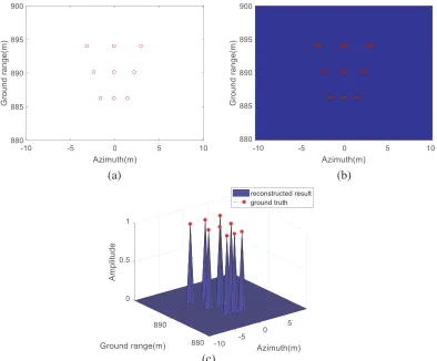
Firstly, imaging of some point scatterers is simulated. Figure 3(a) illustrates the real positions of 9 point scatterers which form a trapezia. The distances between adjacent scatterers are one resolution cell in ground range direction and 2/5, 3/10, 1/5 resolution cell in azimuth direction, respectively. Figure 3(b) shows the imaging results generated by the proposed algorithm. It can be seen that 9 point scatterers are all well focused at right positions. As a result, an exact trapezia is formed in the imaging result, which demonstrates that the proposed algorithm has no less than 5 times super-resolving ability in azimuth direction. Figure 3(c) shows the superposition of the ground truth and the reconstructed results. The good agreement further validates the imaging and super-resolving capability of the proposed algorithm.
(a) (b)
(c)
Figure 3. Forward-looking SAR imaging simulation of 9 point scatterers which form a trapezia. (a) Real positions of 9 point scatterers. (b) Image generated by the proposed algorithm. (c) Comparison between imaging result and ground truth.
(a)
(b) (c)
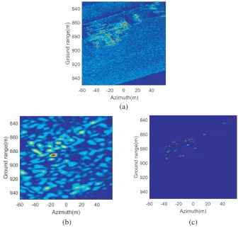
Figure 4. Forward-looking SAR imaging simulation of a building. (a) Ku-band complex valued image of MiniSAR which is used as complex reflective template in forward-looking SAR echo generation. (b) Image generated by the RD algorithm. (c) Image generated by the proposed algorithm.
each scene is 120 m×120 m (ground range×azimuth), then the distances between adjacent scattering points are about 1/10 resolution cell of the forward-looking SAR in both ground range and azimuth directions. In order to make our validation more reliable, we place every scattering point in the complex valued images from the MiniSAR system using a coordinate in ground range-azimuth plane (i.e., xoy plane in Figure 2). In this way, the complex valued images of the MiniSAR system are taken as the complex reflective templates of the scenes (namely g(x, y) in Equation (5)). During simulation, the forward-looking SAR system transmits signal to the scene in front of it, and complex scattering points in the scene backscatter signal to it. By receiving backscattered signal, the echo data of forward-looking SAR are generated, and then the effectiveness of the proposed CS-based algorithm is demonstrated. The simulation parameters are also the parameters listed in Table 1. The corresponding imaging results are shown in Figure 4∼Figure 6.
(a)
(b) (c)
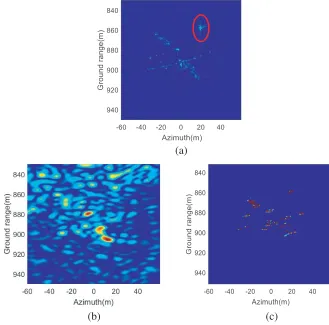
Figure 5. Forward-looking SAR imaging simulation of a C130 plane. (a) Ku-band complex valued image of MiniSAR which is used as complex reflective template in forward-looking SAR echo generation. (b) Image generated by the RD algorithm. (c) Image generated by the proposed algorithm.
not so easy for this complex target, it seems that more details about the building are reconstructed by the proposed algorithm. Thirdly, the sparse image reconstructed by the CS-based algorithm enable the effective use of the automatic target recognition system for detection and recognition [41]. Fourthly, the dense and clean “look” of Figure 4(c) demonstrates the robustness of the proposed algorithm in the presence of noise and clutter, especially when only strong scattering points over a noisy background are of interest. Fifthly, because 5 times oversampling is adopted in range compressing, and azimuth super-resolving processing is carried out along each range sample, the characteristic of the target is also better depicted in range direction by the proposed algorithm, although no designed super-resolving processing is included in range direction.
Comparing Figure 4(a) and Figure 4(c), one may doubt that except for cleaner background, it is hard to conclude that the imaging quality is greatly improved by the proposed algorithm. However, it should be noticed that Figure 4(a) is generated by the MiniSAR system which operates at Ku-band spotlight mode and is utilized as complex reflective template in imaging simulation. However, Figure 4(c) corresponds to an image generated by a forward-looking SAR which operates at forward-looking mode and X-band. For spotlight-mode, the antenna is steered to map a scene at multiple viewing angles during a single pass, so it can provide higher resolution than strip-map and scan mode SAR. However, for forward-looking SAR, as its azimuth resolution is severely limited by azimuth aperture length, how to achieve high resolution image is a problem that should be dealt with. Therefore, it is more reasonable to compare imaging quality at same imaging mode and frequency band, such as Figure 4(b) and Figure 4(c), which correspond to images reconstructed by RD and the proposed algorithm at the same imaging mode and frequency band, respectively.
(a)
(b) (c)
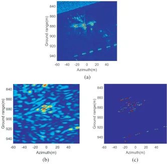
Figure 6. Forward-looking SAR imaging simulation of an Osprey plane. (a) Ku-band complex valued image of MiniSAR which is used as complex reflective template in forward-looking SAR echo generation. (b) Image generated by the RD algorithm. (c) Image generated by the proposed algorithm.
capability enhancement introduced by the proposed algorithm. In this experiment, the size of the two-dimensional radar echo is 466×56, and the size of the scene is 309×158. If the conventional CS-based imaging algorithm is used [39, 40], namely CS is used to improve range and azimuth resolutions simultaneously, the corresponding size of dictionary matrix A will be 26096×48822. It means that 48822 variables should be solved from 26096 equations, which is obviously an extensive computation burden. However, when the proposed algorithm is used, the size of A will reduce to 56×158, which means that 158 variables should be solved from 56 equations. Consequently, the computation efficiency is greatly enhanced.
Figure 5(a) shows the complex valued image of the MiniSAR system. In this image, a C130 plane is parked on the runway. Figure 5(b) shows the image generated by the RD algorithm. Similarly, due to poor resolution, mutual interference of adjacent scattering points lies in the same resolution cell and contamination by noise and clutter, only some strong scattering points can be observed. Consequently, it is difficult for us to find any relationship between them and a plane. In contrast, Figure 5(c) which is reconstructed by the proposed algorithm gives us a much better impression. Firstly, the shape of the C130 plane is well reconstructed, especially the array of scattering points corresponding to the wing and tail of the plane. Secondly, contamination of noise and clutter is eliminated by using the proposed algorithm. Thirdly, in the image reconstructed by the proposed algorithm, the strong scattering point which is highlighted by the red circle in Figure 5(a) is imaged at the right position with strong appearance. Considering that it is an isolated scattering point, this could be deemed as another demonstration for the effectiveness of the proposed algorithm.
the proposed algorithm, respectively. From the image reconstructed by the proposed algorithm, it can be seen that the Osprey plane is well reconstructed that we can recognize it as a plane from its shape. Besides that, the thread-like objects in the lower part of the image are also accurately reconstructed. At the same time, the less spurious background is preferable. The experimental results demonstrate the superiority of the proposed algorithm.
5. CONCLUSION
In this paper, an enhanced forward-looking SAR imaging algorithm based on the CS theory is proposed. Firstly, by separating the imaging process into range compression based on matched filter and azimuth super-resolving reconstruction based on CS, the computational burden is greatly decreased. Secondly, by proposing an iterative regularization implementation of CS, the super-resolving ability is greatly improved. The desirable characteristics of the proposed algorithm are verified using simulated data and Ku-band complex valued image data from the MiniSAR system. In the images reconstructed by the proposed algorithm, the contours and details of the point scatterers, plane and building are well preserved.
In this paper, uniform sampling is used in the proposed forward-looking SAR imaging algorithm based on CS. However, it has been declared in some literatures that sparse sampling configuration has better performance and less computational burden [42, 43]. How to choose sparse samples and its impact on forward-looking imaging performance is our ongoing area of research.
ACKNOWLEDGMENT
This work is partly supported by the National Natural Science Foundation of China (No. 61501473, 61490690) and Excellent Youth Foundation of Hu’nan Scientific Committee (No. 2017JJ1006).
The authors would like to thank the Sandia National Laboratories for providing complex valued image data of the MiniSAR system.
REFERENCES
1. Witte, F., “Forward looking radar,” US Patent 5182562, 1993.
2. Sutor, T., F. Witte, and A. Moreira, “A new sector imaging radar for enhanced vision-SIREV,”
Proceedings of SPIE, 39–47, July 1999.
3. Curlander, J. C. and R. N. McDonough,Synthetic Aperture Radar: Systems and Signal Processing, John Wiley & Sons, 1991.
4. Wang, J. and Z. L. Zong, “Forward-looking SAR imaging algorithm via compressive sensing,”
Radar Science and Technology, Vol. 10, No. 1, 27–31, 2012.
5. Xu, G., Q. Q. Chen, Y. X. Hou, Y. C. Li, and M. D. Xing, “Super-resolution imaging of forward-looking scan SAR,”Journal of Xidian University, Vol. 39, No. 5, 101–108, 2012.
6. Soldovieri, F., G. Gennarelli, I. Catapano, D. Liao, and D. Dogaru, “Forward-looking radar imaging: A comparison of two data processing strategies,”IEEE Journal of Selected Topics in Applied Earth
Observations &Remote Sensing, Vol. 10, No. 2, 562–571, 2017.
7. Chen, Q. and R. L. Yang, “Research of chirp scaling imaging algorithm for air-borne forward-looking SAR,” Journal of Electronics &Information Technology, Vol. 30, No. 1, 228–232, 2008. 8. Ren, X. Z. and R. L. Yang, “Study on three-dimensional imaging algorithm for airborne
forward-looking SAR,” Journal of Electronics &Information Technology, Vol. 32, No. 6, 1361–1365, 2010. 9. Ren, X. Z., J. T. Sun, and R. L. Yang, “A new three-dimensional imaging algorithm for airborne
11. Pang, B., D. H. Dai, S. Q. Xing, and X. S. Wang, “Development and perspective of forward-looking imaging technique,” Systems Engineering and Electronics, Vol. 35, No. 11, 40–47, 2013.
12. Moreira, A., J. Mittermayer, and R. Scheiber, “Extended chirp scaling algorithm for air- and spaceborne SAR data processing in stripmap and ScanSAR imaging modes,” IEEE Trans. on
Geoscience and Remote Sensing, Vol. 34, No. 5, 1123–1136, 1996.
13. Pang, B., S. Q. Xing, D. H. Dai, Y. Z. Li, and X. S. Wang, “Research on forward-looking synthetic aperture radar imaging algorithm of high velocity platform,” Proceedings of IET International
Radar Conference, 1–6, April 2013.
14. Pang, B., X. S. Wang, D. H. Dai, S. Q. Xing, and Y. Z. Li, “Imaging algorithm of high velocity forward-looking SAR based on digital beam sharpening,”Chinese Journal of Radio Science, Vol. 29, No. 1, 1–8, 2014.
15. Yuan, Y., S. Chen, S. N. Zhang, and H. C. Zhao, “A chirp scaling algorithm for forward-looking linear-array SAR with constant acceleration,” IEEE Geoscience and Remote Sensing Letters, Vol. 15, No. 1, 88–91, 2018.
16. Mei, H. W., Z. Q. Meng, M. Q. Liu, Y. C. Li, Y. H. Quan, S. Q. Zhu, and M. D. Xing, “Thorough understanding property of bistatic forward-looking high-speed maneuvering platform SAR,”IEEE
Trans. on Aerospace & Electronic Systems, Vol. 53, No. 4, 1826–1845, 2017.
17. Pu, W., J. J. Wu, Y. L. Huang, W. C. Li, Z. C. Sun, J. Y. Yang, and H. G. Yang, “Motion errors and compensation for bistatic forward-looking SAR with cubic-order processing,”IEEE Trans. on
Geoscience and Remote Sensing, Vol. 54, No. 12, 6940–6957, 2016.
18. Meng, Z. Q., Y. C. Li, M. D. Xing, and Z. Bao, “Property analysis of bistatic forward-looking SAR with arbitrary geometry,” Systems Engineering and Electronics, Vol. 27, No. 1, 111–127, 2016. 19. Xia, J., X. F. Lu, and W. D. Chen, “Multi-channel deconvolution for forward-looking phase array
radar imaging,”Remote Sensing, Vol. 9, No. 7, 703–728, 2017.
20. Zhang, Y., Y. C. Zhang, Y. L. Huang, and Y. L. Yang, “A sparse Bayesian approach for forward-looking superresolution radar imaging,” Sensors, Vol. 17, No. 6, 1353–1368, 2017.
21. Zhang, L., Z. J. Qiao, M. D. Xing, Y. C. Li, and Z. Bao, “High-resolution ISAR imaging with sparse stepped-frequency waveforms,” IEEE Trans. on Geoscience and Remote Sensing, Vol. 49, No. 11, 4630–4651, 2011.
22. Budillon, A., A. Evangelista, and G. Schirinzi, “Three-dimensional SAR focusing from multipass signals using compressive sampling,” IEEE Trans. on Geoscience and Remote Sensing, Vol. 49, No. 1, 488–499, 2011.
23. Baraniuk, R. and P. Steeghs, “Compressive radar imaging,”Proceedings of IEEE Radar Conference, 128–133, April 2007.
24. Austi, C. D., E. Ertin, and R. L. Moses, “Sparse signal methods for 3-D radar imaging,” IEEE
Journal of Selected Topics in Signal Processing, Vol. 5, No. 3, 408–423, 2011.
25. Varshney, K. R., M. Cetin, J. W. Fisher, and A. S. Willsky, “Sparse signal representation in structured dictionaries with application to synthetic aperture radar,” IEEE Trans. on Signal
Processing, Vol. 56, No. 8, 3548–3561, 2008.
26. Gurbuz, A. C., J. H. McClellan, and W. R. Scott, “Compressive sensing for GPR imaging,”
Proceedings of 41st Asilomar Conference on Signals, Systems Computers, 2223–2227, November 4–
7, 2007.
27. Gurbuz, A. C., J. H. McClellan, and W. R. Scott, “Compressive sensing for subsurface imaging using ground penetrating radar,”Signal Processing, Vol. 89, No. 10, 1959–1972, 2009.
28. Zhu, X. X. and R. Bamler, “Tomographic SAR inversion by l1-norm regularization — the compressive sensing approach,”IEEE Trans. on Geoscience and Remote Sensing, Vol. 48, No. 10, 3839–3846, 2010.
29. Patel, V. M., G. R. Easley, D. M. Healy, and R. Chellappa, “Compressed synthetic aperture radar,”
IEEE Journal of Selected Topics in Signal Processing, Vol. 4, No. 2, 244–254, 2010.
30. Cumming, I. G. and F. H. Wong,Digital Processing of Synthetic Aperture Radar Data: Algorithms
31. Cetin, M. and W. C. Karl, “Feature-enhanced synthetic aperture radar image formation based on nonquadratic regularization,” IEEE Trans. on Image Processing, Vol. 10, No. 4, 623–631, 2001. 32. Potter, L. C., E. Ertin, J. T. Parker, and M. Cetin, “Sparsity and compressed sensing in radar
imaging,”Proc. of IEEE, Vol. 98, No. 6, 1006–1020, 2010.
33. Samadi, S., M. Cetin, and M. A. Masnadi-Shirazi, “Sparse representation-based synthetic aperture radar imaging,”IET Radar Sonar & Navigation, Vol. 5, No. 2, 182–193, 2011.
34. Xing, S, D. Dai, Y. Li, and X. Wang, “Polarimetric SAR tomography usingL2,1mixed norm sparse reconstruction Method,”Progress In Electromagnetics Research, Vol. 130, 105–130, 2012.
35. Magnus, J. R. and H. Neudecker, Matrix Differential Calculus with Applications in Statistics and
Econometrics, John Wiley & Sons, 2007.
36. Sun, D., S. Q. Xing, Y. Z. Li, and D. H. Dai, “Adaptive parameter selection of SAR sparse imaging model,”Journal of Remote Sensing, Vol. 21, No. 4, 579–587, 2017.
37. Austin, C. D., R. L. Moses, J. N. Ash, and E. Ertin, “On the relation between sparse reconstruction and parameter estimation with model order selection,” IEEE Journal of Selected Topics in Signal
Processing, Vol. 4, No. 3, 560–570, 2010.
38. Zhang, Y., G. X. Zhou, J. Jin, Q. B. Zhao, X. Y. Wang, and A. Cichocki, “Aggregation of sparse linear discriminant analyses for event-related potential classification in brain-computer interface,”
International Journal of Neural Systems, Vol. 24, No. 1, 1450003, 2014.
39. Pang, B., D. H. Dai, S. Q. Xing, Y. Z. Li, and X. S. Wang, “Imaging enhancement of stepped frequency radar using the sparse reconstruction technique,”Progress In Electromagnetics Research, Vol. 140, 63–89, 2013.
40. Yang, J. G., J. Thompson, X. T. Huang, T. Jin, and Z. M. Zhou, “Random-frequency SAR imaging based on compressed sensing,” IEEE Trans. on Geoscience and Remote Sensing, Vol. 51, No. 2, 983–994, 2013.
41. Cetin, M., W. C. Karl, and D. A. Castanon, “Feature enhancement and ATR performance using nonquadratic optimization-based SAR imaging,” IEEE Trans. on Aerospace and Electronic
Systems, Vol. 39, No. 4, 1375–1395, 2003.
42. Guo, B., D. Vu, L. Z. Xu, M. Xue, and J. Li, “Ground moving target indication via multichannel airborne SAR,”IEEE Trans. on Geoscience and Remote Sensing, Vol. 49, No. 10, 3753–3764, 2011. 43. Stoica, P., J. Li, and H. He, “Spectral analysis of non-uniformly sampled data: A new approach