e-ISSN: 2278-7461, p-ISSN: 2319-6491
Volume 6, Issue 10 [October. 2017] PP: 01-09
Effect of Speed Breaks on Vehicle Dynamics and Ride Comfort
Sabry Allam
1, Fathy Nader
1and M. Rabea
21. Automotive Technology Department, Faculty of Industrial Education, Helwan University, Cairo, Egypt. 2. Automotive Engineering Department, Faculty of Engineering, Minia University, Minia, Egypt.
E-mail of corresponding author: [email protected].
ABSTRACT:
The primary objective of the ride comfort analysis is to study the response behavior of thesprung mass systems subject to different road excitation forces. Speed Bumps are a traffic calming tool designed to slow traffic. They are widely used and gradually increasing on the roads year by year. A Speed Bump is a bump on a roadway that may be circular, parabolic, or sinusoidal. The speed hump design parameters such as height, width, and space as well as the vehicle’s speed are the important factors that affect safety and comfort of passengers. In this paper, the effect of speed hump design parameters at different speeds on vehicle dynamics and ride comfort are experimentally investigated. Throughout this study, a quarter car test rig of Toyota Hiace microbus, which one of the most favorite on the Egyptian roadway is prepared and used. The experimental results show that the vehicle vibration increases with the increasing of bump height, and vehicle speed, while it can be possibly reduced by reducing the tire inflation pressure, and increasing the vehicle weight. Experimental investigation of the effect of a speed bump on the car noise emission level is also presented.
--- ---Date of Submission: 25-09-2017 ---Date of acceptance: 06-10-2017 ---
---I.
INTRODUCTION
Road speed control humps are a kind of forced road traffic safety facilities, which play an important role in curbing the occurrence of traffic accidents [1, 2]. At present, all various speed control bumps are paved on the road; in addition to the common entrance, community and school road install rubber speed control bumps and the accident black spot on the highway, such as highway curve, ramp, and tunnel entrances, generally setting up consecutive speed bumps to force the vehicle deceleration. When the car passes the uneven speed control bumps, severe vibration through the body and the seat is passed from tire to the driver, which makes the driver feel uncomfortable. Thus, the driver will be forced to reduce speed to achieve the goal of speed limit [3– 5].
The automobile suspension system is necessary equipment, which can reduce the vibration generated by the SCHs, improve the vehicle’s driving smoothness and comfort, and reduce the damage of the vehicle and road surface.
Because of the nonlinearities of automobile suspension system and wheels, the nonlinear characteristics existing in the automobile suspension system can lead to suspension system producing complicated dynamic behaviors under uneven road surface excitation, such as chaotic vibration and quasi periodic vibration. When the vibration becomes severe, it will lead the vehicle to jump or overturn [3, 6-7].
Chaotic vibration and quasi periodic vibration may cause shock vibration to the road surface, thus influencing the lifetime of road surface, safety of driving, and the comfort of the driver [8–13].
Effect of Speed Breaks on Vehicle Dynamics and Ride Comfort
consulted concerning the installation of speed humps. Emergency providers may have casualties in their vehicles and going over the humps may affect the injuries which the casualties have. Especially if they are in a life threatening situation, they may need to move as far as possible.
Hessling [16] showed that the comfort changes with car speed and the improper design of road humps leading to a risk of injury. He listed the tools of dynamic measurement systems used in the measurements when the vehicle crossing a speed hump.
Kanjanavapastit and Thitinaruemit [17] stated that a road speed hump can cause an accident, and they proposed a technique to estimate the speed hump profile using a quarter car model. They used accelerometers located on the unsprung mass to measure the axial and vertical accelerations and used MATLAB Simulink to estimate the speed hump profile. Silva and Vasconcelos [18] emphasized that the use of speed humps for their ease of construction / installation and their efficiency in reducing vehicle speeds. They developed a speed profile model using a database and hierarchical multiple regression techniques, providing speeds on the approach and exit of isolated speed humps.
Hassan [19-20] presented a novel simple harmonic speed hump and studied the car dynamics during crossing this hump using a quarter car model. He covers a car hump crossing speed in the range 5-30 km/h, hump length 3-9 m and hump height 60-120 mm. He set a ride comfort diagram to assist simple harmonic hump design for any desired crossing speed between 5 and 30 km/h.
With the reference to the used published list [1-20] and other publish papers have been checked by the authors on the internet, there is no research results in dynamic performance of a torsion bar suspension system, which mainly used in light weight trucks and Microbuses, which are the most used vehicles on the Egyptian roads. A torsion bar suspension, also known as a torsion spring suspension (but not to be confused with torsion beam rear suspension), is a general term for any vehicle suspension that uses a torsion bar as its main weight bearing spring. One end of a long metal bar is attached firmly to the vehicle chassis; the opposite end terminates in a lever, the torsion key, mounted perpendicular to the bar, that is attached to a suspension arm, a spindle, or the axle. The vertical motion of the wheel causes the bar to twist around its axis and is resisted by the bar's torsion resistance. The effective spring rate of the bar is determined by its length, cross section, shape, material, and manufacturing process.
This study mainly focuses on the experimental investigation of chaotic vibration induced by road excitation due to speed humps on laboratory test model for Toyota Hiace microbus, which one of the most favorite on the Egyptian roadway. This study includes the effect of all design and operating parameters on the sprung mass vibration.
II.
EXPERIMENTAL SETUP
To analyze the behavior of the torsion bar suspension system; double-wishbone type of suspension with upper torsion bar was used during the experimental tests. Figure (1) illustrates the arrangement of the quarter car suspension with torsion bar. The experimental setup is composed of electrical motor fitted with a drum has diameter 0.38 m used to rotating the tire has diameter 0.7 m via a belt. Electric motor speed can be controlled by an inverter device to change the drum speed.
To simulate the hump road effect, the drum tire (3) has the freedom to move up and down direction by using a 5 hp electric motor via connecting rod attached to the drum tire. Electric motor speed can be controlled by the inverter device, to change the hump position.
The height of the hump can be changed by using disc has some holes in certain position and rotates by the electric motor as shown in Figure 2. The big end of the connecting rod connects to disc hole and the other attached to the drum. The height of the hump is controlled by changing the position of the contact point of the connecting rod end to the holes in the disc.
Figure (1). Torsion bar test rig.
1. Electrical motor for hump, 2. Electrical motor for drum, 3. Drum, 4. Hump system, 5. Tire, 6. Torsion bar, 7. Quarter car suspension assembly, 8. Vibration sensor position, 9. Bolt of the torsion bar.
Figure (2) Photo of the drive motor and the hump height mechanism. 1. Electrical motor, 2. Chain, 3. Drum, 4. Connecting rod.
During the measurements, the road is considered as cam which will give harmonic road excitation to the suspension system. The road profile is approximated by a sine wave with 50mm amplitude, the wavelength of road surface is 1.57 m, angular velocity () is 8.33 rad/s and frequency (f) of 1.32 Hz at 7.5 km/hr. Both angular velocity and frequency are varied during the measurements according to vehicle speed.
III. RESULTS AND DISCUSSIONS
Through this study different design; hump height and space, tire air pressure as well as operating parameters; vehicle weight and speeds on the vehicle dynamics and ride comfort are studied. A summary of this study will be presented here.
3.1 Effect of vehicle load on the ride comfort.
Effect of Speed Breaks on Vehicle Dynamics and Ride Comfort
These values are changed with vehicle speed as shown in Appendix (A).
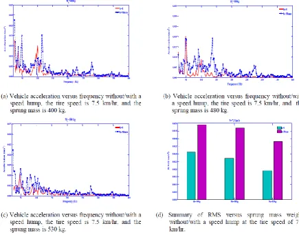
Figure (3) Vehicle acceleration versus sprung mass weight without/with a speed hump at tire speed of 7.5km/hr.
3.2 Effect of tire speed on the vehicle vibration.
The effect of tire speed on the vehicle vibration at sprung mass weight of 530 kg is presented in Figure 4. It can be seen that the sprung mass acceleration has increased with the increasing of vehicle speed in both cases without and with speed humps. Without speed hump, the RMS value of the body acceleration increases 25 % with the increase of tire speed from 2.5 km/hr to 5 km/hr and 25 % when it increases from 5 km/hr to 7.5 km/hr. With speed humps height 50 mm, the RMS value of the body acceleration increases 8.8 % with the increase of tire speed from 2.5 km/hr to 5 km/hr and 2.7 % when it increases from 5 km/hr to 7.5 km/hr. The variation of RMS values at different loads can be found in Appendix (B).
Figure (4) Vehicle acceleration versus tire speed without / with a speed hump at different tire speeds.
3.3 Effect of the tire inflation pressure on vehicle vibration.
The effect of the tire inflation pressure on the ride comfort at tire speed of 7.5 km/hr and sprung mass weight of 480 kg is presented in figure 5. Without speed hump, the RMS value of the body acceleration is increased by 4.2 % when the tire inflation pressure is changed from 55 psi to 60 psi, while, the RMS value is increased by 3.7 % when the tire inflation pressure is changed from 55 psi to 60 psi with speed humps height of 50 mm as shown in Figure (5-b).
Effect of Speed Breaks on Vehicle Dynamics and Ride Comfort
3.4 Effect of type of gas filling tire on the ride comfort.
The effect of the type of gas filling tire on the ride comfort is presented in figure (6). It can be seen that the type of gas has also clear effect on vehicle vibration. The difference between the RMS values with air filling tire and nitrogen filling tire at without speed hump is 10 %, while with speed hump of 50 mm height, it has increased 5% respectively as shown Figure (6-b).
50 100 150 200 250 300 350 400
0.000 0.005 0.010 0.015 0.020 0.025 0.030 0.035
Frequency ( Hz)
A c c e le r at ion ( m /s 2) h=50mm Pair Pnitrogen
0.000 h=0 h=50mm
0.0005 0.0010 0.0015 0.0020 0.0025 0.0030 0.0035 0.0040 0.0045 R .M .S ( m /s 2)
V=7.5km/h M
s=530kg
Pair Pnitrogen
(b) Summary of RMS versus air filling the tire and
gas filling tire, and different tire speeds without/with a speed hump at Ms=530 kg. )a) Vehicle acceleration versus frequency with
speed hump, the tire speed of 7.5 km/hr, and Ms=530 kg.
Figure (6) Effect of gas filling tire on vehicle acceleration without/with a speed hump at Ms=530 kg.
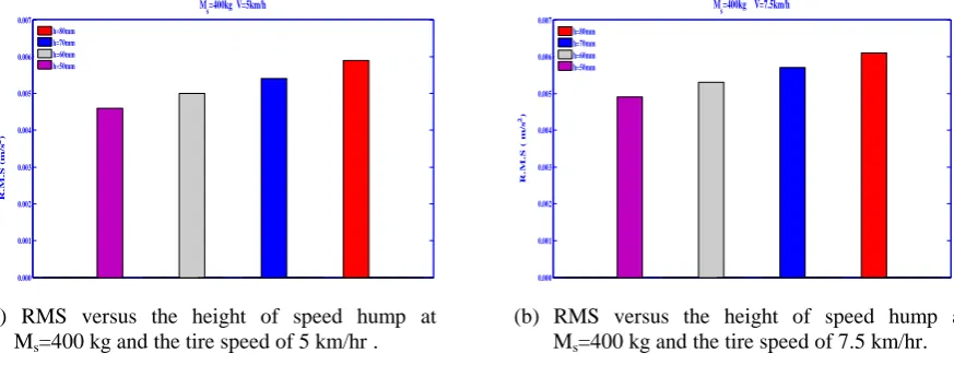
3.5 Effect of height of the hump on the vehicle vibration
The effects of hump's height on vehicle noise at different speeds are shown in Figure (7). It can be seen that the RMS increases linearly by 8.5% when the height of humps increased 10mm at different speeds. The effect of speed variation on the increasing of RMS is small around 2% at each hump.
0.000 0.001 0.002 0.003 0.004 0.005 0.006 0.007 R .M .S ( m /s 2) M
s=400kg V=5km/h h=80mm h=70mm h=60mm h=50mm 0.000 0.001 0.002 0.003 0.004 0.005 0.006 0.007 R .M .S ( m /s 2) M
s=400kg V=7.5km/h h=80mm
h=70mm h=60mm h=50mm
(b) RMS versus the height of speed hump at
Ms=400 kg and the tire speed of 7.5 km/hr. )a) RMS versus the height of speed hump at
Ms=400 kg and the tire speed of 5 km/hr .
Figure (7) RMS versus the height of speed hump at sprung mass weight 400 kg at different speeds.
3.6 Effect of load and speed on vehicle noise
Figure (8) Vehicle noise versus sprung mass weight at different tire speeds without/with a speed hump.
IV.
CONCLUSIONS AND FUTURE WORK
A quarter-car test rig with torsion bar, passive elements was used in this study to investigate the car dynamics during passing a speed hump and the following conclusion can be drawn:
The increase of vehicle load decreases vehicle vibration due to the increasing in the damping of the suspension system.
For tire speed 7.5 km/hr with a speed hump by increasing the vehicle load from (unload to quarter load), the vehicle vibration decreases 6 %, and 19 % from (quarter load to half load),also by increasing the vehicle load from (half load to 3/4 load), the vehicle vibration decreases 22 % , and 23% from (3/4 load to full load).
For half vehicle load by increasing the tire speed from 5 to 7.5 km/hr, the vehicle vibration increases 6 % without speed hump, and 6.5 % with speed humps. Also the vehicle vibration increases 13.6 % by increasing the tire speed from 10 to 15 km/hr, without speed hump, and 12.7 % with speed humps.
The increasing of tire pressure by 10% for half load vehicle increased vehicle vibration by 4.2% without speed hump and 3.7% with speed humps at tire speed 7.5 km/hr.
By using the nitrogen filling tire, it increases the vehicle vibration at full load from 6% to 10% without speed hump and from 3% to 6 % with speed humps at different speeds.
Using the speed hump increases the vehicle noise about 13%.
Vehicle vibration increases linearly with the height of the speed humps.
Effect of Speed Breaks on Vehicle Dynamics and Ride Comfort
REFERENCES
[1] F. Liu, S. Liang, Q. Zhu, and Q. Xiong, “Effects of the consecutive speed humps on chaotic vibration of a nonlinear vehicle model,” ICIC Express Letters, vol. 4, no. 5, pp. 1657–1664, 2010.
[2] B. Anti´c, D. Peˇsi´c, M. Vujani´c, and K. Lipovac, “The influence of speed bumps heights to the decrease of the vehicle speed-Belgrade experience,” Safety Science, vol. 57, pp. 303–312, 2013.
[3] S. Liang, C. Li, Q. Zhu, and Q. Xiong, “The influence of parameters of consecutive speed control humps on the chaotic vibration of a 2-DOF nonlinear vehicle model,” Journal of Vibroengineering, vol. 13, no. 3, pp. 406–413, 2011.
[4] X. Wang and Y. He, “Projective synchronization of fractional order chaotic system based on linear separation,” Physics Letters A, vol. 372, no. 4, pp. 435–441, 2008.
[5] X. Wang, X. Zhang, and C. Ma, “Modified projective synchronization of fractional-order chaotic systems via active sliding mode control,” Nonlinear Dynamics, vol. 69, no. 1-2, pp. 511–517, 2012.
[6] S. Liang, Y. Sun, Q. Zhu, and Z. Yang, “Ride comfort analysis of a nonlinear vehicle excited by the consecutive speed-control humps,” Journal of Vibroengineering, vol. 15, no. 4, pp. 1668–1676, 2013. [7] Z. Yang, S. Liang, Y. Sun, and Q. Zhu, “Chaos of a Nonlinear half-vehicle suspension system excited by
the consecutive speed-control humps,” ICIC Express Letters, vol. 7, no. 11, pp. 3163–3168, 2013. [8] A. Sezgin and Y. Z. Arslan, “Analysis of the vertical vibration effects on ride comfort of vehicle driver,”
Journal of Vibroengineering, vol. 14, no. 2, pp. 559–571, 2012.
[9] L. Zuo and P.-S. Zhang, “Energy harvesting, ride comfort, and road handling of regenerative vehicle suspensions,” Journal of Vibration and Acoustics, Transactions of the ASME, vol. 135, no. 1, Article ID 011002, 2013.
[10] X. Wang and Y. Wang, “Adaptive control for synchronization of a four-dimensional chaotic system via a single variable,” Nonlinear Dynamics, vol. 65, no. 3, pp. 311–316, 2011.
[11] Y.-J. Liu and Y.-Q. Zheng, “Adaptive robust fuzzy control for a class of uncertain chaotic systems,” Nonlinear Dynamics, vol. 57, no. 3, pp. 431–439, 2009.
[12] D. J. Li, “Adaptive output feedback control of uncertain nonlinear chaotic systems based on dynamic surface control technique,” Nonlinear Dynamics, vol. 68, no. 1-2, pp. 235–243, 2012.
[13] Y.-J. Liu, C. L. P. Chen, G.-X. Wen, and S. Tong, “Adaptive neural output feedback tracking control for a class of uncertain discrete-time nonlinear systems,” IEEE Transactions on Neural Networks, vol. 22, no. 7, pp. 1162–1167, 2011.
[14] Duane E. Smith, and Karen L. Giese “A Study on Speed Humps” Center for Transportation Research and Education Iowa State University Ames, IA 50011 September 1997
[15] UK Essays '' The Effects Of Speed Humps On Vehicles'' May, 2017. https://www.ukessays.com/essays/engineering/
[16] J. Hessling, “Analysis and synthesis of speed limiting road humps” Second Meeting on Analysis of Dynamic Measurements, London 18/11, 2008.
[17] A. Kanjanavapastit and A. Thitinaruemit, “Estimation of speed hump profile using quarter car model”, Social and Behavioral Sciences, 88, 256-273, 2013.
[18] A. Silva and A. Vasconcelos “Development of a speed profile model for isolated speed humps” The 93rd Annual Meeting of the Transportation Research Board, Washingto, 12-16 January, 1-12, 2014.
[19] G. A. Hassaan “Car dynamics using quarter model and passive suspension, Part II: A novel simple harmonic hump” Journal of Mechanical and Civil Engineering, 12 (1), 93-100, 2015.
[20] G. A. Hassaan “Car Dynamics Using Quarter Model and Passive Suspension, Part III: A Novel Polynomial Hump” Journal of Mechanical and Civil Engineering, 12 (1), 51-57, 2015.
[21] MATLAB User’s Guide Copyright 1994-2017.
Appendix (A) Effect of load vehicle on the ride comfort Height speed hump (mm) Body
vertical acceleration ( m/s2)
0 50
Tire speed 2.5 km/h Body vertical acceleration (m/s 2
) at Ms= 400 kg 0.0024 0.0045
Body vertical acceleration (m/s2) at Ms= 480 kg 0.0015 0.0042 Body vertical acceleration (m/s2) at Ms =530 kg 0.0012 0.0034
Tire speed 5 km/h Body vertical acceleration (m/s 2
) at Ms= 400 kg 0.0029 0.0046
Body vertical acceleration (m/s2) at Ms= 480 kg 0.0025 0.0043 Body vertical acceleration (m/s2) at Ms =530 kg 0.0015 0.0037
Tire speed 7.5 km/h Body vertical acceleration (m/s 2) at M
s= 400 kg 0.0031 0.0049
Appendix (B) Effect of tire speed on the ride comfort
Height speed hump (mm) Body vertical acceleration ( m/s2)
0 50
Load vehicle 400 kg
Body vertical acceleration (m/s2) at V= 2.5 km/h 0.0024 0.0045 Body vertical acceleration (m/s2) at V= 5 km/h 0.0029 0.0046 Body vertical acceleration (m/s2) at V= 7.5 km/h 0.0031 0.0049
Load vehicle 480 kg
Body vertical acceleration (m/s2) at V= 2.5 km/h 0.0015 0.0042 Body vertical acceleration (m/s2) at V= 5 km/h 0.0025 0.0043 Body vertical acceleration (m/s2) at V= 7.5 km/h 0.0027 0.0047
Load vehicle 530 kg
Body vertical acceleration (m/s2) at V= 2.5 km/h 0.0012 0.0034 Body vertical acceleration (m/s2) at V= 5 km/h 0.0015 0.0037 Body vertical acceleration (m/s2) at V= 7.5 km/h 0.0019 0.0038
Appendix (C)
Effect of the tire inflation pressure on the ride comfort (Without speed hump)
The tire inflation pressure (psi)
Body vertical acceleration ( m/s2)
55 60
Load vehicle 400 kg
Body vertical acceleration (m/s2) at V= 2.5 km/h 0.0024 0.0026 Body vertical acceleration (m/s2) at V= 5 km/h 0.0029 0.0031 Body vertical acceleration (m/s2) at V= 7.5 km/h 0.0031 0.0033
Load vehicle 480 kg
Body vertical acceleration (m/s2) at V= 2.5 km/h 0.0015 0.0016 Body vertical acceleration (m/s2) at V= 5 km/h 0.0025 0.0026 Body vertical acceleration (m/s2) at V= 7.5 km/h 0.0027 0.0028
Effect of the tire inflation pressure on the ride comfort (With a speed hump)
The tire inflation pressure (psi)
Body vertical acceleration ( m/s2)
55 60
Load vehicle 400 kg
Body vertical acceleration (m/s2) at V= 2.5 km/h 0.0045 0.0047
Body vertical acceleration (m/s2) at V= 5 km/h 0.0046 0.0047
Body vertical acceleration (m/s2) at V= 7.5 km/h 0.0048 0.0049
Load vehicle 480 kg
Body vertical acceleration (m/s2) at V= 2.5 km/h 0.0042 0.0043
Body vertical acceleration (m/s2) at V= 5 km/h 0.0043 0.0045