.
Abstract—Generalized Predictive Controller is a one type of
Model Predictive Controller. Speed Control of DC motor is taken as a Case study for validation of GPC controller algorithm implementation on Real Time Hardware. There is a much gap between theoretical solution and real time implementation of MPC. Basically MPC works better for slow dynamic system, so here efforts are made to Implement MPC for Fast Dynamic System. System Identification of DC motor is done using a LABVIEW and system identification tool of MATLAB. First of all ARIX model based GPC controller is designed in MATLAB for Model Obtained from System Identification of DC motor. Then the control law of GPC controller is implemented on ATMEGA328P and Results shows that GPC controller gives better results than discrete time PID controller for Set Point Tracking as well as for Disturbance Rejection.
Index Terms—MPC (Model Predictive Controller), GPC
(Generalized Predictive Controller), ARIX Model (Auto Regressive Integrated Exogenous Model, FDS (Fast Dynamic System).
I. INTRODUCTION
Model Predictive Controller is basically suitable only for Slow Dynamic Systems like Chemical Process, Oil Refineries, etc. Design of MPC for Fast Dynamic system is difficult because MPC takes long time to calculate the value of control action and if the sampling time of control action is larger than the FDS like DC motor will not reach at the Desired Set Point. So MPC with small sampling time and less computation time will be used for FDS.
There are many types of MPC control algorithms used. Some of them are listed here: 1) GPC (Generalized Predictive Controller), 2) DMC (Dynamic Matrix Controller), 3) Steady State Weighted Generalized Predictive Control, etc. Generally GPC controller is used for Fast Dynamic System. Here GPC controller results are compared with PID controller for DC motor Speed Controller. PID and PI controller are also used for Fast Dynamic System.
There is much gap between real time implementation and theoretical solution of MPC. So here, effort is made for real time implementation of GPC for DC motor Speed Control. More detail on MPC and GPC control algorithm is given in [2] and [6]. Now a day’s many researchers tries to reduce the computation time of MPC.
Manuscript received June, 2015.
Sumit G. Vyas1Student of M.E., Instrumentation and Control Engineering, L.D. College of Engineering, Ahmedabad,Gujarat, India
Vinodkumar P. Patel2 Associate Professor, Instrumentation and Control Engineering, L.D. College of Engineering, Gujarat, India
In [1] Generalized Predictive controller results for DC motor is compared to Discrete time Predictive Controller. More detail and survey on Model Predictive Controller is given in [2]. In [3] MPC is implemented for PMSM motor, Generalized Predictive Controller is applied to control the Position of Induction Motor in [4]. Robust Model Predictive Controller is implemented for Fast Dynamic Vehicle System in [5]. Above all MPC is designed particularly for specific application.
In Section II GPC control Strategy is given, In Section III description of DC motor is given, Section IV Describes the System Identification of the System. In Section V Simulation result and effect of tuning parameter of GPC on System Output is shown. Section VI describes the real time implementation of GPC and PID controller for DC motor Speed Control is given.
II. GENERALIZEDPREDICTIVECONTROLLER GPC is based on minimizing a weighted sum of the Set Point error and the control effort and it allows plant models to be updated frequently.GPC makes use of the j-step ahead prediction error model.
ARIX model based Generalized Predictive Control law is given by the following equation,
𝑢 = 𝑘𝑟 − 𝑘𝐻
2𝑦
𝑜𝑙𝑑− 𝑘𝐻
1𝑢
𝑜𝑙𝑑 WhereG =
𝑔
𝑘,00
… 0
𝑔
𝑘+1,1𝑔
𝑘+1,0⋯ 0
⋮
𝑔
𝑘+𝑁,𝑁⋮
𝑔
𝑘 +𝑁,𝑁−1⋮
⋯ 𝑔
𝑘 +𝑁,0 ,𝐻
1=
𝑔
𝑘 ,1⋯
𝑔
𝑘,𝑑𝐺𝑘𝑔
𝑘 +1,2⋯
𝑔
𝑘+1,𝑑𝐺𝑘 +1⋮
𝑔
𝑘+𝑁,𝑁+1⋮
⋯
⋮
𝑔
𝑘+𝑁,𝑑𝐺𝑘 +𝑁 , 𝐻2= 𝑓𝑘 ,0 ⋯ 𝑓𝑘,𝑑𝐴 𝑓𝑘 +1,0 ⋯ 𝑓𝑘+1,𝑑𝐴 ⋮ 𝑓𝑘 +𝑁,0 ⋮ ⋯ ⋮ 𝑓𝑘+𝑁,𝑑𝐴 ,𝑦
𝑜𝑙𝑑 =[𝑦 𝑛 … … … … 𝑦(𝑛 − 𝑑𝐴)]
𝑇,
Real Time Implementation and Design of
Predictive Controller for Fast Dynamic System
𝑢
𝑜𝑙𝑑 =∆𝑢 𝑛 − 1 … … … ∆𝑢 𝑛 − 𝑘 + 1 − 𝑑𝐵
𝑇,𝑢
=∆𝑢 𝑛 … … … . ∆𝑢 𝑛 + 𝑁
𝑇,where
𝑟
is a trajectory of reference signals.𝑟
=[𝑟 𝑛 + 𝑘 … … … 𝑟(𝑛 + 𝑘 + 𝑁)]
𝑇,
𝑘 = (𝐺
𝑇𝐺)
−1𝐺
𝑇,In the above Generalized Predictive Control law, the error signal and the control effort are weighted over the same length of time.
Now, generalizing this situation by minimizing the error from n+k+N1 to n+k+N2, N2≥N1 and the control effort from n to n + Nu.
The performance index is given by
𝐽
𝐺𝑃𝐶= [𝑦 𝑛 + 𝑘 + 𝑁
1− 𝑟(𝑛 + 𝑘 + 𝑁
1)]
2+
… … …+
[𝑦 𝑛 + 𝑘 + 𝑁
2− 𝑟(𝑛 + 𝑘 + 𝑁
2)]
2+
𝜌[∆𝑢(𝑛)]
2+ … … … + 𝜌[∆𝑢(𝑛 + 𝑁
𝑢)]
2As a result of this
𝑦
and𝑢
given by𝑦 = [𝑦 𝑛 + 𝑘 + 𝑁
1… … … 𝑦 (𝑛 + 𝑘 + 𝑁
2) ]
𝑇𝑢
=∆𝑢 𝑛 … … … . ∆𝑢 𝑛 + 𝑁
𝑢𝑇
The performance of the GPC depends on the parameters N1, N2, Nu and ρ. So the proper selection of these parameters
gives better results. Tuning of these parameters is necessary which is given in the [6], [7] and [8]. More detail on GPC controller is given in [6].
III. DCMOTOR
To validate the proposed MPC algorithm, Speed Control of DC Motor is taken as a Case Study for Fast Dynamic System. DC Motor Specification is given below. Generally the MPC gives better results for Slow Dynamics System so here efforts are made to Implement GPC control algorithm for DC motor Speed Control.
A. DC Motor Specification
Fig (1) show the DC motor used to validate the GPC algorithm. Rotating Magnet mechanism on the pulley is put on motor to give the load on the DC motor to checks whether the GPC controller can rejects the disturbance or not. Specifications:
1. Maximum speed: 1500 Rpm
2. Maximum input Voltage: 10 V DC
3. Maximum input Current: 0.9Amp
4. F to V converter output: 0 to 2 volt for 0 to 1500 rpm.
Fig- 1: DC motor
IV. SYSTEMIDENTIFICATION
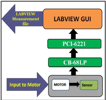
System Identification uses the different statistical methods to generate the model of the System using real time data of input and output of the system with respect to time measured in LABVIEW. LABVIEW stores the input and output measured data of the system with respect to time at 0.001 sampling time. This data are used in the system identification tool of the MATLAB to generate the model of the system. Figure (2) shows the Interfacing of DC Motor with LABVIEW for the System Identification of the Motor.
Fig-2: Interfacing of DC motor with LABVIEW to store
the value of input and output values in a Measurement File As shown in figure DC motor is interfaced with LABVIEW to obtain the model of the DC Motor and stored data of input and output of the Motor is used in the system
identification tool of the MATLAB. Figure (3) show the output and input waveform of the motor stored in the File using LABVIEW. Figure (4) shows the estimated output of the obtained model of the DC motor.
The Estimated model of the DC motor is obtained as below,
𝐺 𝑆 =
0.5957 𝑆 + 0.0683
𝑆
2+ 3.248 𝑆 + 0.339
With one zero and two pole and the estimated transfer function fits the data by 89.54%.
Transfer function of DC motor in Z domain is obtained as below,
G z = 0.0321 z − 0.03187 z2− 1.825 z + 0.8256
Fig- 3: Input and Output response of measured data of DC
motor
Fig- 4: Response of Actual System and Simulated Model of
DC motor
V. SIMULATIONRESULTS
This section shows the simulation Results of the DC motor model with GPC controller and its results are compared with discrete time PID controller. Sampling time Ts = 0.059s taken to implement the PID and GPC controller. PID tuning is done using Ziegler Nichols closed loop Method.
Obtained value of PID tuning parameter are Kp = 6.02, Ti = 0.05 and Td = 0.019. Then this parameter are used to implement the discrete time PID controller using following Equation, 𝑆0= 𝐾𝑝 1 + 𝑇𝑠 2𝑇𝑖 + 𝑇𝑑 𝑇𝑠 𝑆1= 𝐾𝑝 −1 + 𝑇𝑠 2𝑇𝑖 − 2𝑇𝑑 𝑇𝑠 𝑆2= 𝐾𝑝 𝑇𝑑 𝑇𝑠
Discrete Time PID Controller is given by, 1 − 𝑍−1 𝑢 𝑛 = 𝑆
0+ 𝑆1𝑍−1+ 𝑆2𝑍−2 𝑒(𝑛)
Tuning parameter of GPC are N1, N2, Nu and rho. Values of tuning parameter of GPC are taken are N1 = 0, N2 = 10, Nu = 5 and rho = 0.5.
N1 = Starting point of Prediction Horizon, N2 = End point of Prediction Horizon, Nu = Control Horizon,
rho = Control Weighting parameter.
For all case Set Point of DC Motor taken is 700 rpm
A. DC Motor’s Response without Disturbance
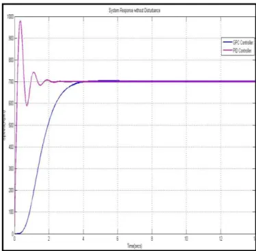
Motor’s closed loop response with PID controller and GPC controller are show in figure (5). In this response, no disturbance is given.
Fig-5: System Response without Disturbance
Figure (5) shows the both GPC and PID controller output response without Disturbance. From the simulation results of
the GPC and PID Controller, it is concluded that settling time of GPC controller is 4 seconds while PID Controller takes 3seconds. So from settling time perspective PID is better than GPC controller but PID controller have large Oscillation then GPC controller. GPC controller gives smooth tracking of the Set Point as compared to PID controller.
Fig – 6: Control Action Responsewithout Disturbance
Figure (6) shows the Control action response of the PID and GPC Controller.
B. DC Motor’s Response with Disturbance
In this case step disturbance is applied after 10 seconds. Both the Controller takes almost same time to rejects the disturbance. System Response with Disturbance is shown in figure (7).
Fig –7: System Response with Disturbance
Figure (8) shows the Control action Response of PID and GPC Controller. Because of Disturbance, Oscillation occurs in both controllers at time of 10 seconds. It shows that both controllers reject the Disturbance effectively. Time taken to remove the disturbance is almost same for both controller and it is approximately 2 to 2.5 seconds.
Fig –8: Control action Response with Disturbance C. Set Point Tracking Results of DC Motor
In this case variation in the Set Point is given. For 25 seconds Set Point value is 700 rpm and for another 25 seconds Set Point value is taken be 0. Figure (9) shows Set point tracking of GPC controller is very smooth while PID controller oscillated Set Point Tracking.
Fig – 9: System Response for Set Point Tracking
Figure (10) shows the control action response of GPC and PID controller for Set Point tracking case study.
Fig – 10: Control Action Response for Set Point Tracking D. Effect of GPC Tuning Parameter on the System Output
In this section effect of GPC tuning parameters on the System Output is shown. Figure (11) shows the effect of control horizon on System Output. For in all case Control Horizon Nu = 5 is taken. Decreasing the value of Nu gives oscillated output while increasing the value of Nu makes system slow. For Nu = 5 it gives better results for system output.
Fig – 11: Effect of Control Horizon (Nu) on System Output
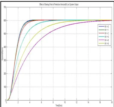
Figure (12) shows the effect of Starting Point of Prediction Horizon on System Output. For N1 = 0 it gives good results but when increasing the value of N1 it makes system very slow.
Fig – 12: Effect of Starting Point of Prediction Horizon (N1)
on System Output
Figure (13) shows the effect of End Point of Prediction Horizon. For all cases N2 = 10 is taken. For N2 = 6 system output is very slow and it takes more time to reach at set point. For N2 = 13 continuous oscillation occurs in the system output. So Small value of N2 makes system very slow and large value of N2 makes system oscillated. So for N2 = 10 it gives system output have neither slow response nor oscillated response.
Fig – 13: Effect of End Point of Prediction Horizon (N2) on
System Output
Remaining tuning parameter of GPC is Control Weighting Parameter (rho). In figure (14) effect of the value of rho on system output is shown. So it effects almost same as control horizon parameter on system output. For rho = 0.3 it gives oscillated response on system output and for rho = 0.8 system output have slow response. So for small value of rho system output have oscillated response and for rho near to 1 have
slow response on system output. For rho = 0.5 it system output have neither oscillated response nor slow response.
Fig – 14: Effect of Control Weighting Parameter on System
Output
VI. REAL TIME IMPLEMENTATION OF GPC AND PID CONTROLLER
In Previous section all are simulation results of GPC and PID controller, here results are of real time data of GPC and PID controller is shown. Fig (15) shows the interfacing of DC motor with Arduino Uno board. In Arduino Uno board recursive function of eq (1) is implemented in C++ language.
Fig – 15: Interfacing of DC Motor with Arduino Uno Board A. GPC Control Algorithm
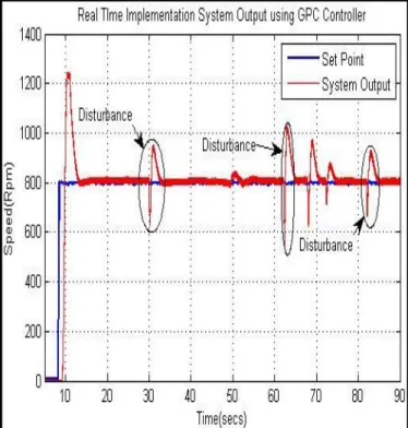
Figure (16) shows the real implementation of GPC controller to check the whether GPC rejects the Disturbance or not peak in circle shows the disturbance given on Motor using Magnet. It is show that GPC rejects the disturbance very well. Blue line shows the reference Trajectory. From the results it is concluded that using GPC Controller Motor takes approximately 3 to 4 second to reach at the desired Speed and it rejects the disturbance in approximately 1 to 2 seconds.
Fig – 16: Motor Response for Disturbance Rejection Using
Motor Response fGPC Controller
Motor Response for Set Point Tracking using GPC Controller is shown in figure (17). There are two values of Set Point taken, first one is 900 Rpm and another is 500 Rpm. Each Set Point is given to Motor for 20 seconds. From the results it is concluded that using GPC Controller DC Motor tracks the Set Point Smoothly. Blue line in the Results shows the Reference Trajectory. It follows the Set Point smoothly after 1 to 2 seconds. Set Point tracking and Disturbance Rejection of the DC Motor using GPC Controller give better results than the PID Controller.
Fig – 17: Motor Response for Set Point Tracking Using GPC
B. Discrete Time PID Control Algorithm
DC Motor’s Response for Disturbance Rejection Using Discrete time PID Controller is shown in figure (18). Set Point is 800 RPM is taken. From the results it is concluded that GPC Controller have better results than Discrete time PID Controller. There is large oscillation occurs in Discrete time PID Controller. DC Motor takes 15 seconds initially to reach at the desired Speed using PID Controller. Disturbance on DC motor generates large oscillation and it takes more time to rejects the Disturbance than GPC Controller. Settling time and Overshoot both are large in PID Controller than GPC Controller.
Fig – 18: Motor Response for Disturbance Rejection Using
PID Controller
DC Motor’s Output Results for Set Point Tracking using PID Controller is shown in figure (19). Same as GPC controller, here also two Set Point values are given to DC Motor for Set Point Tracking. Results show that for Set Point Tracking GPC controller gives better performance than PID controller.
Fig – 19: Motor Response for Set Point Tracking Using PID
Controller
There is large oscillation in PID Controller for Set Point Tracking. It takes 15 to 16 seconds to settle at a desired set point which is larger than GPC controller. Overshoot is also larger in Discrete time PID Controller than GPC controller.
There is also a difference between Simulation Results and Real Time Implementation Results of GPC and PID Controller for DC Motor Speed Control.
VII. CONCLUSION
From the Results of Real Time Performance and Simulation of the DC Motor, it is concluded that GPC controller gives better results for both the Set Point Tracking and Disturbance Rejection than Discrete Time PID controller. DC Motor using GPC Control takes only 3 to 4 seconds to reach at the Desired Set Point while Discrete Time PID Controller takes approximately 15 seconds to reach at the Desired Set Point which is larger than the GPC Control. In Disturbance Rejection case study, Discrete Time PID Controller have more effects of Disturbance and it takes more time to reject that disturbance while GPC control rejects Disturbance and Continuous Load effects in small time than PID controller. GPC gives Smooth and Stable Performance than Discrete Time PID Control Algorithm. GPC control algorithm performance depends on the proper selection of tuning parameters which are Control Horizon (Nu), Starting and End point of Prediction Horizon, Control Weighting parameter (rho). As Shown in simulation results, for taking Nu = 2 System have oscillated output while taking Nu = 7 settlingtime of System is increases. For Nu = 5, System has smooth response. neither it has slow response nor has oscillated Response. For End point of Prediction Horizon N2 = 13, system have continuous oscillation and for N2 = 6, settling time of system is increases. So for N2 = 10, system has smooth response neither it is slow nor oscillated response. Generally Starting Point of Prediction Horizon N1 = 0 is taken. After proper selection of tuning parameters, GPC control algorithm gives smooth and stable response for DC Motor Speed Control.
REFERENCES
[1] Sumit G. Vyas, Vinodkumar P. Patel, “Design of Predictive Controller For Smooth Set Point Tracking of Fast Dynamic Controller” , Volume 04, Issue 04, IJRET April -2015.
[2] Yu-Geng Xi, De-Wei, Shu LIN, “Predictive Control -Status and Challenges” Vol.39, No.3, ActaAutomaticaSinica, ScienceDirect, March -2013. [3] GionataCimini, Valentino Fossi, GianlucaIppoliti,
Stefano Mencarelli, Giuseppe Orlando and MatteoPirro, “Model Predictive Control Solution for Permanent Magnet Synchronous Motors”, Industrial Electronics Society, IECON 2013, IEEE.
[4] Antonio B.S.Junior, Francisco G. Sena, Bismark C. Torrico, Luiz H.S.C. Barreto,”Generalized Predictive Control Applied to the Position Control of a Induction Motor”, Industry Application, IEEE, 2012.
[5] T. Peni, J. Bokor, “Robust Model Predictive Control for Controlling Fast Vehicle Dynamics”, Control and Automation 2006, IEEE.
[6] “Digital Control” by KannanMoudgalya.pp.438-443& 312-320.
[7] “Model Based Predictive Control of Electrical Drives” by Arne Linder, Rahul Kanchan, Ralph Kennel, Peter Stolze.
[8] Junxia Mu and David Rees, “Approximate Model Predictive Control for Gas Turbine Engines”, Proceeding of the 2004 American Control Conference, June-July 2004.
[9] “The Good Gain Method for PI and PID Controller Tuning” by Finn Haugen.
[10] “Model Predictive Control” by Eduardo F. Camacho and Carlos Bordons.
[11] Yang Su, KokKiong Tan, Tong Heng Lee, “Computation Delay Compensation for real time implementation of robust model Predictive Control”, Journal of Process Control, ELSEVIER,2013.
[12] Vihangkumar V. Naik, D.N. Sonawane, Deepak D. Ingole and DivyeshGinoya, “Model Predictive Control of DC servomotor using Active Set Method”, IEEE Multi-Conference on Systems and Control, IEEE, 2013.
[13] S. Joe Qin, Thomas A. Badgwell, “A Survey of Model Predictive Control Technology”, Control Engineering Practice, Science Direct, 2003.
[14] Mark L. Darby, Michael Nikolaou, “MPC: Current Practices and Challenges”, Chemical Engineering Practices, 2012.
[15] “PID Controller: Theory, Design and Tuning” by K. Astrom and T. Hugglund. Pp.134-138.