Abstract— This paper proposes the design of Multivariable
Robust Anti-windup Generalized Predictive Control (MRAGPC) scheme for multivariable processes with input constraints and disturbances. The proposed scheme embodies both the optimal attributes of continuous-time anti-windup generalized predictive control and the robust feature of operator-based theoretic approach. As a result, a strongly robust stable feedback control system with disturbance rejection feature and output-reference input tracking is achieved.
Index Terms— anti-windup, input constraints and disturbance, robust predictive control, MIMO systems.
I. INTRODUCTION
Predictive control strategy has been a central research focus in recent times[1]-[5].The main objective of a reliable control scheme is believed to guarantee stability of the controlled system, minimize the influence of disturbances, noises, perturbations, track the output to the desired command input and generally optimize the control performance. In practice, control systems have to deal with disturbances of all kinds, such as stepwise load disturbances, high frequency sensor or thermal noise. In adaptive control, although the underlined control scheme may have a good setpoint tracking response and disturbance rejection, these disturbances may give rise to wrong parameter estimates and thus results in bad control performance or worst still an unstable system.
The new proposed structure under the generalized scheme of Predictive Control is known as Multivariable Robust Anti-windup Generalized Predictive Control (MRAGPC). It is so named because it shares the attributes of MCAGPC and operator based theoretic design for non-linear systems. Though operator-based theoretic approach has been used widely for control of non-linear systems the idea as well can be extended to linear systems since control engineers find it easier working with linearized model than its non-linear form. So if a linearized model of a system can be obtained about some operating point, then optimal robust control design can be achieved by chosen a control strategy that satisfies both control optimal performance and robustness. Whereas MCAGPC design satisfies the optimal design criteria, the operator-based method is good for robust
Manuscript received July 26, 2009.
A. S. Osunleke is a Ph.D. Student at the Division of Industrial Innovation Science, Graduate School of Natural Science and Technology, Okayama University, 3-1-1 Tsushima Naka, Kitaku 3-chome, Okayama 700-8530, Japan ([email protected]).
M. Deng, is an Associate Professor with Department of Systems Engineering, Okayama University, 3-1-1 Tsushima Naka, Kitaku 3-chome, Okayama 700-8530, Japan (phone: +81-86-251-8234; fax: +81-86-251-8924; e-mail: [email protected]).
A. Yanou is an Assistant Professor with Department of Systems
performance design. As for the proposed MRAGPC, it is both optimal as well as robust.
This work proposes a design procedure for Multivariable Continuous-time Generalized Predictive Control for system with both input constraints and disturbances. The proposed MRAGPC design procedure entails firstly, the construction of stable right coprime factors of the controlled systems. Secondly, anti-windup controllers are designed for realizing a stable closed loop around process input-output loop. Next is the construction of Bezout identity operators for obtaining a stable feedback closed loop system. This procedure is completed by the design of a tracking operator using operator-based theoretic approach [6]. Based on this procedure, the robust stability of the closed-loop system in the presence of input constraint and disturbances is achieved. In this design, effect of interactions between components of the MIMO systems is minimized by choosing appropriate MCAGPC parameters [1]. The effectiveness of this proposed scheme is confirmed by simulation of a real model of two inputs two outputs system with and without disturbance.
II.PROBLEM STATEMENT
The proposed linear multivariable system model is given by [7].
ሺݏሻܻሺݏሻ = ሺݏሻܷሺݏሻ + ሺݏሻܸሺݏሻ ሺ1ሻ
where Y(s), U(s), V(s) are p x 1 output, p x 1 input and
p x 1 disturbance vectors respectively. B(s) is a p x q
polynomial matrix while A(s) and C(s) are p x p diagonal polynomial matrices. As before, the polynomial matrices A(s) and B(s), A(s) and C(s) are coprime. The elements of C(s) are with a degree of one less or equal to that of the corresponding elements of A(s) and are chosen by the designer. The model in (1) corresponds to a Left Matrix Fraction Description (LMFD) described as
ࡼሺݏሻ = ିሺݏሻሺݏሻ ሺ2ሻ
Equation (2) can be equivalently expressed as
ࡼሺݏሻ = ࡰିሺݏሻࡺሺݏሻ ሺ3ሻ
where P0(s) is the nominal multivariable plant, D0(s) and
N0(s) are coprime factors of P0(s) and are defined as
ࡺሺݏሻ = ࡰ෩ିሺݏሻ෩ሺݏሻ
ࡰሺݏሻ = ࡰ෩ିሺݏሻሺݏሻቋ ሺ4ሻ
where ࡰ෩ሺ࢙ሻ is a Hurwitz polynomial matrix with degree
equal to that of ሺ࢙ሻ. The polynomial matrix ෩ሺ࢙ሻ is the
MRAGPC Control of MIMO Processes with
Input Constraints and Disturbance
same as B(s) for a non-strict proper system (ߩ= 0), but for a strict proper system (ߩ> 0), ෩ሺ࢙ሻ is given as
෩ሺݏሻ ≅ ࢌ෨ሺݏሻ + ሺݏሻ ሺ5ሻ
and polynomial matrix ࢌ෨ሺݏሻ in (5) is designed as
ࢌ෨ሺݏሻ = ሺߜ ∗ ݏ + 1ሻ࣋࢘ ሺ6ሻ
where ߩ is the relative order of the original system and ߜ is any small positive constant such that all the roots of the polynomial ሺߜݏ + ሻ࣋࢘ lie on the origin of the complex
plain. It can easily be established that as ߜ → 0, the polynomial matrix ෩ሺݏሻ ≅ ሺݏሻ. Equation (5) enables easy computation of the proposed design scheme. The optimal value of ߜ that gives good approximation of the model (5) can be achieved using [7].
The control input uj(t) is subject to the following
constraint.
ݑ,≤ ݑሺݐሻ ≤ ݑ௫,ሺ݆ = 1, 2, … , ሻ. ሺ7ሻ
The constraint (3) is equivalently expressed as
࢛ሺݐሻ = ߪሺ࢛ଵሻ = ൮
ߪ൫ݑതଵሺݐሻ൯
⋮
ߪቀݑതሺݐሻቁ
൲ , ࢛ଵ= [ݑതଵሺݐሻ ⋯ ݑതሺݐሻ]்
࣌ሺݒሻ = ቐ
࢛௫, , if ࢜ > ࢛௫,
࢜, if ࢛, ≤ ࢜ ≤ ࢛௫, ሺ8ሻ
࢛, , if ࢜ < ࢛,
where u1 is the ideal controller output vector. The objective is to design as before a MCAGPC system using coprime factorization and Youla-Kucera parameterization for the above process.
III. PROPOSED CONTROLLERS DESIGN
The proposed design scheme for the MIMO systems follows four steps as highlighted below.
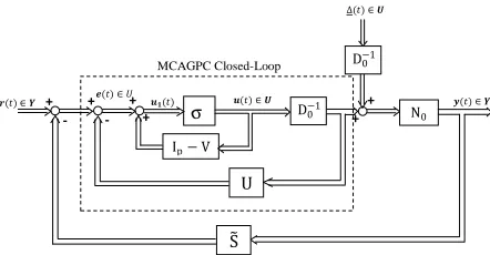
A. Design of Stable Feedback MCGPC Controllers R(s), V (s) and U (s) with Input Constraint part (Fig.1).
[image:2.612.68.289.585.700.2]By adapting the MCGPC design method to the anti-windup design approach [3], [4], the proposed controllers is given by Youla-Kucera parameterisation [5] as follows.
Figure 1. Proposed MIMO Control Structure
ࡾሺݏሻ = ൫ࢅሺݏሻ − ࡽሺݏሻࡺሺݏሻ൯ିଵࡷሺݏሻ ሺ9ሻ
ࢁሺݏሻ = ࢄሺݏሻ + ࡽሺݏሻࡰሺݏሻ ሺ10ሻ
ࢂሺݏሻ = ࢅሺݏሻ − ࡽሺݏሻࡺሺݏሻ ሺ11ሻ
where Q(s)∈RH∞ is a design parameter matrix for ensuring a
strongly stable feedback controllers in the above and is given by
ࡽሺݏሻ = ࢁࢊሺݏሻିଵࢁሺݏሻ ሺ12ሻ
N(s), D(s) are the coprime factor representation of ࡰିሺݏሻ .
X(s), Y(s) ∈RH∞ are operators chosen to satisfy the Bezout
Identity
ࢄሺݏሻࡺሺݏሻ + ࢅሺݏሻࡰሺݏሻ = ࡵ ሺ13ሻ
where N(s) and D(s) are defined as
ࡺሺݏሻ = ࢀࢉିሺݏሻࡰ෩ሺݏሻ
ࡰሺݏሻ = ࢀࢉିሺݏሻሺݏሻቋ ሺ14ሻ
X(s) and Y(s) are as defined in the previous works [1], [4] as
ࢄሺݏሻ = ࡷࢋࡾࢋ+ ࡷࢋࢋሺݏሻࡲሺݏሻ ሺ15ሻ
ࢅሺݏሻ = ࡵ+ ࡷࢋࢋሺݏሻࡳሺݏሻ ሺ16ሻ
Tc(s) is the closed-loop characteristic polynomial matrix for
the control system in Figure 1 and is given by
ࢀሺݏሻ = ሺݏሻ + ࡷࢋࡸሺݏሻ + ࡷࢋࡾࢋࡰ෩ሺݏሻ ሺ17ሻ
where Ke, Ce, Re, G(s) and F(s) are given in [1].
B. Robust Stability of D0
-1
(s) with Input Constraint.
The CAGPC part shown in Fig. 2 is non-linear with respect to the effect of input constraint. R-1D0-1(s) is the closed loop transfer function of the CAGPC structure and it is always stable and invertible. Therefore, it can be seen that the plant retains a robust rcf and it is stable. Then, we can design a non-linear operator ࡿ෨ሺݏሻ to satisfy the following Bezout
Identity [4].
ࡾ෩ሺ࢙ሻࡰሺݏሻ + ࡿ෨ሺ࢙ሻࡺሺݏሻ = ࡵ ሺ18ሻ
࢟ሺݐሻ ∈ ࢅ σ
࢘ሺݐሻ ∈ ࢅ
∆ሺݐሻ ∈ ࢁ
ࢋሺݐሻ ∈ ܷ
MCAGPC Closed-Loop
Ip− V
N0
U
S෨ ࢛ሺݐሻ ∈ ࢁ ࢛ሺݐሻ
D0−1
D0−1 +
+ +
- +
-
Figure 2. Feedback Stability Design for the MIMO System.
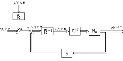
C.Tracking Operator Design
Here a tracking operator M for reference signal w such that plant output y(t) tracks to the reference signal r(t) as depicted in Fig. 3. Based on the proposed lemma and proof in [6], operator M(s) is designed to satisfy
ࡺሺݏሻ൫ࡹሺݏሻࢃሺݏሻ + ࡾ෩ሺݏሻ∆ሺݏሻ൯ = ࡵࢃሺݏሻ ሺ19ሻ
Figure 3. Robust Tracking Structure for the MIMO System.
D.Decoupling of the control system
In the proposed control scheme, the possible interactions between different control loops are identified as input-input, disturbance-input and input-output. In order to minimize the effect of these interactions, the following design steps are proposed.
(i) Choosing larger value for control orders and/or smaller value for the maximum prediction horizons and/or using reference models for the output in the design step A. (ii) Design a decoupling matrix GD(s) such that each loop does not affect the others. The elements of GD(s) can be selected in a number of ways to achieve optimally decouple control system. This is further investigated in the future works.
IV. SIMULATION EXAMPLES
The process examples considered in this section is simulated for both disturbance-free and disturbance systems.
A.Disturbance-free MCAGPC Control
[image:3.612.77.290.48.155.2]The parameters of the 2-input 2-output systems is given in Table 1 below.
Table 1. Simulation parameters for Disturbance-free Control Design.
System Parameters Control Parameters
ܣଵଵ = ݏଶ+ ݏ + 0.1
ܣଶଶ= ݏଶ+ 0.5ݏ + 0.06
ܤଵଵ= −0.2ݏ + 10
ܤଵଶ= 0.5ݏ + 2
ܤଶଵ = 0.1ݏ + 1.2
ܤଶଶ = −0.25ݏ + 6
ܥଵଵ= ܥଶଶ= ݏ + 0.8
݉ = = 2
ܰ௬ଵ= 10, ܰ௬ଶ= 10
ܰ௨ଵ= 3, ܰ௨ଶ= 3
ݎ݉ଵ= 0.5, ݎ݉ଶ= 0.5
ܷଵଵ= 0.75, ܷଶଶ= 0.75
ݑଵ,ଵ= ݑଵ,ଶ= 0
ݑଶ,ଵ= ݑଶ,ଶ= 0.1
ݓଵ= 10, ݓଶ= 2
ߣଵ= ߣଶ= 0.1
ܶଵ,ଵ= ܶଵ,ଶ= 0
ܶଶ,ଵ= ܶଶ,ଶ= 6
ܷௗ= ܫ
B.Model with Disturbance
[image:3.612.74.288.306.385.2]The process model considered for the system with input disturbance is a similar second-order system with disturbance input given as ∆(t) = 20 ݏ݅݊గଶݐ. The process and control parameters are as shown in Table 2.
Table 2. Simulation parameters for System with Input Disturbance.
System Parameters Control Parameters
ܣଵଵ = ݏଶ+ ݏ + 0.1
ܣଶଶ= ݏଶ+ 0.5ݏ + 0.06
ܤଵଵ= −0.2ݏ + 10
ܤଵଶ= 0.5ݏ + 2
ܤଶଵ = 0.1ݏ + 1.2
ܤଶଶ = −0.25ݏ + 6
ܥଵଵ= ܥଶଶ= ݏ + 0.8
݉ = = 2
q = 1
ܰ௬ଵ= 12, ܰ௬ଶ= 12
ܰ௨ଵ= 3, ܰ௨ଶ= 3
ݎ݉ଵ= 1, ݎ݉ଶ= 1
ܷଵଵ= 0.45, ܷଶଶ= 0.45
ݑଵ,ଵ= ݑଵ,ଶ= 0
ݑଶ,ଵ= ݑଶ,ଶ= 0.1
w1 =10, w2 = 2
ߣଵ= ߣଶ= 0.1
ܶଵ,ଵ= ܶଵ,ଶ= 0
ܶଶ,ଵ= ܶଶ,ଶ= 6
ܷௗ= ܫ
IV. RESULTS AND DISCUSSIONS
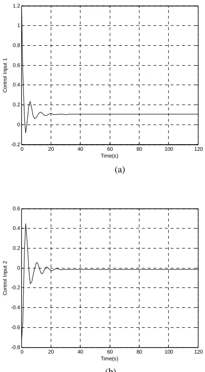
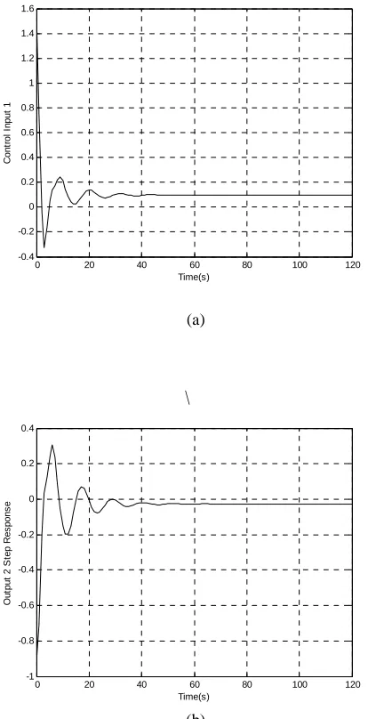
Figs 4(a) and (b) show the control input before constraints while Figs 5(a) and (b) show the control input after the constraints are applied. The outputs from the control inputs are displayed in Figs 6(a) and (b). It is apparent from these results that our proposed control scheme tracks to the reference inputs and keeps the inputs within the limitations of the system for the case of disturbance-free mode design. Figs 7 through 9 show the step response of the Control inputs before constraints, after constraints and the system outputs for case of process example 2 with input constraints and disturbance feature. In these results, it is obvious that our proposed control design penalizes the control error, maintains the input limitations and also tracks the output to the command reference input. The sluggish nature of the output step response observed might be due to the presence of possible loop-to-loop interactions of the control system components. It is evidence from these results that these coupling effects can be considerably minimized by choosing appropriate MCAGPC design parameters.
D0−1
࢟ሺݐሻ ∈ ࢅ
࢘ሺݐሻ ∈ ࢅ ࢋሺݐሻ ∈ ࢁ
S෨
࢛ሺݐሻ ∈ ࢁ
R෩−1 N0
+ -
∆ሺݐሻ ∈ ࢁ
R෩
+ +
࢟ሺݐሻ ∈ ࢅ ࢘ሺݐሻ ∈ ࢅ
Ip N0
࢛ሺݐሻ ∈ ࢁ
M
∆ሺݐሻ ∈ ࢁ
R෩
࢛ሺݐሻ ∈ ࢁ +
(a)
[image:4.612.78.284.54.428.2](b)
Figure 4. System Control Input Step Responses before Constraints
(a)
(b)
(a)
(b)
0 20 40 60 80 100 120
-0.2 0 0.2 0.4 0.6 0.8 1 1.2
Time(s)
C
o
n
tr
o
l
In
p
u
t
1
0 20 40 60 80 100 120
-0.8 -0.6 -0.4 -0.2 0 0.2 0.4 0.6
Time(s)
C
o
n
tr
o
l
In
p
u
t
2
0 20 40 60 80 100 120
0 0.01 0.02 0.03 0.04 0.05 0.06 0.07 0.08 0.09 0.1
Time(s)
C
o
n
tr
o
l
In
p
u
t
1
0 20 40 60 80 100 120
0 0.01 0.02 0.03 0.04 0.05 0.06 0.07 0.08 0.09 0.1
Time(s)
C
o
n
tr
o
l
In
p
u
t
2
0 20 40 60 80 100 120
0 1 2 3 4 5 6 7 8 9 10
Time(s)
O
u
tp
u
t
1
S
te
p
R
e
s
p
o
n
s
e
0 20 40 60 80 100 120
0 1 2 3 4 5 6
Time(s)
O
u
tp
u
t
2
S
te
p
R
e
s
p
o
n
s
[image:4.612.320.524.55.224.2]e
[image:4.612.81.282.486.656.2](a) \ (b) (a) (b) (a) (b)
0 20 40 60 80 100 120
-0.4 -0.2 0 0.2 0.4 0.6 0.8 1 1.2 1.4 1.6 Time(s) C o n tr o l In p u t 1
0 20 40 60 80 100 120
-1 -0.8 -0.6 -0.4 -0.2 0 0.2 0.4 Time(s) O u tp u t 2 S te p R e s p o n s e
0 20 40 60 80 100 120
0 0.01 0.02 0.03 0.04 0.05 0.06 0.07 0.08 0.09 0.1 Time(s) C o n tr o l In p u t 1
0 20 40 60 80 100 120
0 0.01 0.02 0.03 0.04 0.05 0.06 0.07 0.08 0.09 0.1 Time(s) O u tp u t 2 S te p R e s p o n s e
0 20 40 60 80 100 120
0 1 2 3 4 5 6 7 8 9 10 Time(s) O u tp u t 1 S te p R e s p o n s e
0 20 40 60 80 100 120
[image:5.612.79.286.55.459.2]0 1 2 3 4 5 6 7 8 Time(s) O u tp u t 2 S te p R e s p o n s e
Figure 7. Process System Example 2 Control Input Step Responses before Constraints
[image:5.612.319.524.55.225.2]V.CONCLUSION
In this work, a design problem for MIMO system in the presence of input constraints with disturbances and disturbances-free are considered. From the obtained results of the simulations, the following conclusions could be drawn with regards to the performance of the proposed control scheme:
1) The proposed MRAGPC design scheme shows good robust performance and tracks output to the command reference input in the presence of input constraints and disturbance for the two cases considered.
2) The optimal feature of the proposed MRAGPC contributes to decoupling of inter-loop interactions usually present in MIMO control problems. It was also noted that, the choice of MRAGPC design parameters greatly influences the behavior of the control system. In these two cases, a good choice of maximum prediction horizons and or control orders is found to reduce the coupling effects between the loops, whereas, using a reference model adversely affects the performances of the system in both cases of disturbance and disturbances-free.
REFERENCES
[1] H. Dermircioglu and P.J. Gawthrop, Multivariable Continuous-time Generalized Predictive Control (MCGPC), Automatica, 28, No. 4, pp. 697-713 (1992).
[2] M. Deng and A. Inoue, Application of an anti-windup multivariable continuous-time generalized predictive control to a temperature control of an aluminum plate, Int. J. Modeling, Identification and Control, 2, No.2: pp. 130-1733 (2007).
[3] Yanou, A. and Inoue, A., An extension of multivariable continuous-time generalized predictive control by using coprime factorization approach, Proceedings of SICE Annual Conference in
Fukui, pp. 3018-3022, (2003).
[4] Zhou, K., Doyle, J.C. and Glover, K., Robust and Optimal Control, Prentice-Hall, (1996).
[5] M. Deng, A. Inoue, K. Ishikawa and Y. Hirashima, Tracking of perturbed nonlinear plants using Robust Right Coprime Factorization Approach, Proc. of the 2004 American Control Conference 2004, pp. 3666-3670.
[6] Deng,M., Inoue, A. and Ishikawa, K., ‘Operator-based Nonlinear feedback control design using robust right coprime factorization”,
IEEE Transaction on Automatic Control, Vol. 51, No. 4, pp.
645-648, 2006.
[7] Osunleke, A.S., O. Taiwo, and Gabar, H.A., OPTIMRED: an application Package for optimal model reduction, Proc. of the 2nd