PSO Based PID Controller for BLDC Motor
S.Rathika
1, Dr.C.S.Ravichandran
2PG Student [Power Electronics and Drives], Sri Ramakrishna Engineering College, Coimbatore, Tamil Nadu, India1 Professor, Department of EEE, Sri Ramakrishna Engineering College, Coimbatore, Tamil Nadu, India2
ABSTRACT-Brushless DC Motor (BLDC) has more advantages like high efficiency, speed ranges, long operating life, compactness, less maintenance. The BLDC motor performance can be controlled and improved by using controller .The Proportional-Integral-Derivative (PID) controller is the most common and useful method in most applications for stability improvement. The controller parameters used to improve the step response as well as performance characteristics of BLDC Motor. Effective tuning of PID controller parameters is the main criteria to improve the performance characteristics. The conventional methods need manual tuning of PID parameters i.e., trial and error method. Optimization method used to get optimal values of PID. Especially PSO algorithm used to tune and to get optimal gain values of PID iteratively to control the performance of BLDC motor. In this project, conventional PID controller parameters tuning method is compared with the proposed method and the results are obtained. The design and analysis of the PSO based PID controller is simulated using MATLAB. The results obtained from simulation show the significant improvement in performance of BLDC than the existing methods.
KEYWORDS:Brushless DC Motor, Proportional Integral Derivative controller, Particle Swarm Optimization, Ziegler Nichols Method and Fuller‟s scheme.
I.INTRODUCTION
Brushless Direct Current (BLDC) motors are one of the motor types rapidly gaining popularity in recent years because of its high efficiency, high starting torque, noiseless operation and long operating life. BLDC motors are used in many industries such as automotive, industrial automation, aerospace, consumer and instrumentation [3].
There are many modern control methodologies such as optimal control, variable structure control, nonlinear control, and adaptive control have been broadly proposed for speed control of a brushless permanent magnet DC motor. However, these methods are difficult to implement. PID controller is used for control purpose and its three parameters functionality covering treatment for transient and steady-state response offers the simplest and gets most efficient solution to many real world control problems. Even though it has simple structure, optimal gain tuning of PID controllers are quite difficult [1].
Traditional methods like Ziegler-Nichols method and Fuller‟s scheme giving approximate gain values of PID controller. It needs manual tuning and also it consumes more time [5]. Newly, the computational intelligence has proposed Particle Swarm Optimization (PSO) technique. PSO first found by Kennedy and Eberhert, is one of the modern metaheuristic technique.PSO has a reliable and a well-balanced mechanism to enhance the global and local optimum solution. PSO is used to design of PID controller optimally for a brushless DC motor [2].The results obtained from the proposed method and the conventional methods are compared through the performance characteristics of BLDC motor.
II.RELATED WORK
Tuning of PID controller parameters for BLDC motor design is an important process to get improved performance characteristics. The proposed method used to get optimal gains of PID controller.
An inverter design with hysteresis or pulse width modulation (PWM) technique switching is commonly used speed control method of BLDC motor, which has more applications in the field of industries and domestic. PWM control method is a better method to the complex and unclear model systems. it can give simple and effective control [4]
A reduced order system is obtained for higher order linear discrete time system which preserves the stability and retains the characteristics of original system and by using Routh stability array and Particle Swarm Optimization (PSO) can get the improvements in performance of the system [5].So, The effective tuning of PID controller which has done by PSO for BLDC motor [2]. It can modify this control for different motors.
III.BRUSHLESS DC MOTOR AND MODL CONCEPT
As the name implies, BLDC motors do not use brushes for commutation, because BLDC motors are electronically commutated motor. BLDC motors have many advantages over brushed DC motors and induction motors. They are as follows better speed versus torque characteristics, high dynamic response, noiseless operation, long operating life, smaller volume, and simple system structure. The stator windings in BLDC motor are energized in sequence for the motor to rotate. Also there is no physical contact between the stator and the rotor. The important part of the BLDC motor is hall sensors. The arrangements of the hall sensors to the rotor should be in correct manner and they are used as sensing device to sense the rotor position.
The BLDC motor for this project is the EC 45 flat 45 mm, brushless, 30 Watt from Maxon motors. The order number of the motor is 200142[3]
SI.NO FACTORS VALUE UNIT 1 Nominal voltage 12 V
2 No load speed 4370 Rpm 3 No load current 151 Ma 4 Nominal speed 2860 Rpm 5 Nominal current 2.14 A 6 Stall torque 255 mNm 7 Starting current 10 A 8 Maximum efficiency 77 % 9 Terminal resistance phase to phase 1.1 Ω 10 Terminal induction phase to phase 0.50 mH 11 Torque constant 24.5 mNm/A 12 Speed constant 35.4 rpm/V 13 Mechanical time constant 16.1 Ms 14 Rotor inertia 82.5 gcm2 15 No of pole pairs 8
Table 1 BLDC Motor specifications
Transfer function of BLDC motor, G s =
1 K e
τmτes2+τms+1 ___(1)
Where, τe = L
3R, τm =
3R∅J
KeKt
After substituting required values in the above equations,
G s = 14.4928
Figure 1 Step response of open loop transfer function
IV.PID CONTROLLER
The Proportional-Integral-Derivative (PID) controller is the most common and useful algorithm in most applications for stability improvement. In many cases, feedback loop are controlled using the PID algorithm. The main reason is to attain a set point irrespective of disturbances or any variations in characteristics of any form. The PID controller is designed to reduce errors between the measured
values and a particular desired set-point in a system. Controller efficiency depends on the P, I and D parameters. Generally The controller is designed to control the overall behavior of the system. The controller parameters can affect different performance factors of stability of the system. So, that each should be selected properly for better performance.
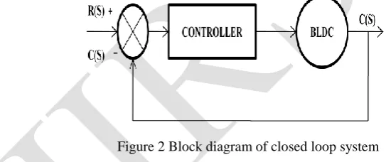
Figure 2 Block diagram of closed loop system
The major goal of the PID parameters is to attain a fast rise time with minimum overshoot and no steady state error. The combination of these three controllers will increase performance of the system and stability of the system.
Kp + (Ki/s) + Kd s = (Kd s2 + Kp s + Ki) / s __(3)
Where, Kp – Proportional gain, Ki – Integral gain, Kd- Derivative gain
Selection of PID controller parameters by suitable method for proposed system
Provides on extremely stable system
Simple mathematical calculation
Need less time for tuning parameter
V.PID CONTROLLER TUNING PARAMETERS
Figure 3 Block diagram of optimal PID control
VI.ZIEGLER-NICHOLS METHOD
The Ziegler-Nichols has simple mathematical procedures, to tune the PID controllers. These procedures are now accepted as standard in control system practice. There are two types in Z-N method. Formal one is are based on plant step responses. Later one based on assumption [1].
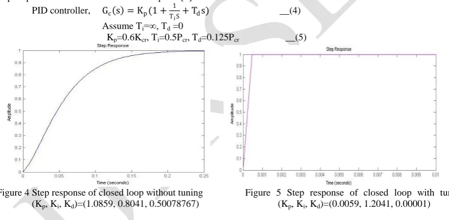
PID controller, Gc s = Kp(1 + 1
TiS+ Tds) __(4)
Assume Ti=∞, Td =0
Kp=0.6Kcr, Ti=0.5Pcr, Td=0.125Pcr __(5)
Figure 4 Step response of closed loop without tuning Figure 5 Step response of closed loop with tuning (Kp, Ki, Kd)=(1.0859, 0.8041, 0.50078767) (Kp, Ki, Kd)=(0.0059, 1.2041, 0.00001)
VII.FULLER’S SCHEME METHOD
Fuller‟s scheme is mainly follows the new algebraic criterion for stabilization. The PID parameters are tuned in this fuller‟s scheme by Hurwitz determinants and Pseudo determinants [6]. From the reduced order Pseudo determinant matrices can obtain the three PID controller parameters Kp, Ki and Kd.
The essential condition for absolute stability is formulated as:
No absent term in the characteristic polynomial F (S).
All coefficients in the characteristic polynomial must have same sign.
In addition to the above essential conditions, the sufficient conditions are obtained from the following procedure. In this procedure, individual are not obtained, but by doing some mathematical operations, the Hurwitz determinants results are arrived.
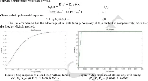
Gc s =
Kds2+ Kps + Ki
s __(6)
T(s)=F(s)|s=s2 + s ( F'(s)|s=s2 ) __(7)
Characteristic polynomial equation,
1 + Gp s Gc s = 0 __(8)
This Fuller‟s scheme has the advantage of reliable tuning. Accuracy of this method is comparatively more than the Ziegler-Nichols method.
Figure 6 Step response of closed loop without tuning
Figure 7 Step response of closed loop with tuning (Kp, Ki, Kd)= (0.5161, 3.5400, 0.5001) (Kp, Ki, Kd)= (0.0161, 3, 0.0001)
VIII.PARTICLE SWARM OPTIMIZATION
Particle Swarm Optimization (PSO) is a computational method that optimizes problem by iteratively trying to improve a candidate solution with regard to a given measure of quality. PSO is a population based stochastic optimization technique which is inspired by social behaviour of bird flocking or fish schooling [4].PSO shares many similarities with evolutionary computation techniques such as Genetic Algorithms (GA). The system is initialized with a population of random solutions and searches for optima by updating generations. In PSO, the possible solutions, called particles, fly through the problem space by following the current optimum particles.Each particle's movement is influenced by its local best known position but, is also guided toward the best known positions in the search-space, which are updated as improved positions are found by other particles. This has to move the swarm toward the best solutions
Each particle keeps track of its coordinates in the problem space which are associated with the best solution (fitness) it has achieved so far. (The fitness value is also stored.) This value is called pbest. Another "best" value that is tracked by the particle swarm optimizer is the best value, obtained by any particle in the neighbours of the particle. This location is called lbest. When a particle in search space takes all the population as its possible neighbours, the best value is a global best in search space and is called gbest.The PSO concept consists of, at each step, changing the velocity of (accelerating) each particle toward its pbest and lbest locations (local version of PSO). Acceleration of a particle is weighted by a random term, with separate random numbers is generated for acceleration toward pbest and lbest locations.
ALGORITHM
1. Create a „population‟ of agents (particles) uniformly distributed over X 2. Evaluate each particle‟s position according to the objective function
6. Move particles to their new positions:
Pit+1
=
Pit+
Vit+1 ___(11) 7. Go to step 2 until stopping criteria are satisfiedHere integrated absolute error (IAE) has been used for fitness value and it should be minimized for better performance. In past several years, PSO has been successfully applied in many research and application areas. It is confirmed that PSO gets better results in a faster, cheaper way compared with other conventional methods. Another reason that PSO is attractive is that there is small number of parameters to adjust. One version, with minor variations, works well in a wide variety of applications. PSO has been used for approaches that can be used across a wide range of applications, as well as for precise applications focused on a specific requirement.
IX.SIMULATION RESULTS
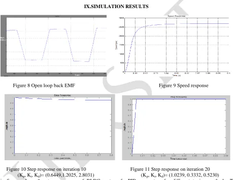
Figure 8 Open loop back EMF Figure 9 Speed response
Figure 10 Step response on iteration 10 Figure 11 Step response on iteration 20 (Kp, Ki, Kd)= (0.6449,1.2025, 2.8031) (Kp, Ki, Kd)= (1.0239, 0.3332, 0.5230)
This figures show the step responses of BLDC motor of PID parameters for different tuning methods. The conventional methods need manual tuning. Trial and error method come to play in the conventional methods.
X.DISCUSSION
Table 2 Comparison of performance
Tuning Methods Kp Ki Kd Rise Time Settling Time
The step response of conventional methods and PSO method are shown above. As shown in the step response of all methods, proposed PSO method has good performance characteristics. The settling time and rise time are reduced when compared with conventional methods. Thus by PSO based PID controller has more advantage for BLDC motor.
XI.CONCLUSION
The performance and stability of the BLDC motor had improved by tuning PID parameters effectively using MATLAB and this method results compared with conventional method results. The simulation results show that the proposed controller can perform an efficient search for the optimal gains of PID controller. Through comparing between PSO method and conventional techniques, it shows that PSO method can improve the dynamic performance of the system in a better way.The proposed method of performance improvement Of BLDC motor is robust, efficient and easy to implement.
REFERENCES
[1] H.E.A. Ibrahim, F.N. Hassan, Anas O.Shomer,” Optimal PID control of a brushless DC motor using PSO and BF techniques”,Ain Shams
Engineering Journal,2014.
[2] Mehdi Nasri, Hossein Nezambadi-pour,Mahilhe Maghfoori,”A PSO-Based Optimum Design of PID Controller for a linear Brushless DC
Motor“,International Journal of Electrical, Robotics, Electronics and communication engineering,2007.
[3] Vinod KR Singh Patel, A.K.Pandey “Modeling and Performance Analysis of PID Controlled BLDC Motor and Different Schemes of PWM
Controlled BLDC Motor”,International Journal of Scientific and Research Publications, Volume 3, Issue 4, April 2013.
[4] Mahmud Iwan Solihin, Lee Fook Tack and Moey Leap Kean,”Tuning of PID Controller Using Particle Swarm Optimization (PSO)”,
International Conference on Advanced Science,Engineering and Information Technology 2011.
[5] Oludayo John Oguntoyinbo”PID control of BLDC motor and Robot trajectory planning and simulation with MATLAB/
SIMULINK”,university of applied sciences.
[6] Porkumaran,”New Algebric Criterion For Analysis And Design Of Linear Systems” Ph.D-thesis,Bharathiyar University,2004.
[7] Zwe-Lee Gaing, Member, IEEE,”A Particle Swarm Optimization Approach for Optimum Design of PID Controller in AVR System”, IEEE
TRANSACTIONS ON ENERGY CONVERSION, VOL. 19, NO. 2, JUNE 2004.
[8] Belsam Jeba Ananth M,”Performance analysis of BLDC,SRM and PMS motor using controllers and optimization techniques” , Ph.D-thesis,