DEFINITY
®
Enterprise Communications Server and
System 75 and System 85 Terminals and
Adjuncts Reference Manual
555-015-201
Comcode 107955320
Issue 8
All Rights Reserved Printed in U.S.A. Notice
Every effort was made to ensure that the information in this book was complete and accurate at the time of printing. However, information is subject to change.
Your Responsibility for Your System’s Security
Toll fraud is the unauthorized use of your telecommunications system by an unauthorized party, for example, persons other than your com-pany’s employees, agents, subcontractors, or persons working on your company’s behalf. Note that there may be a risk of toll fraud associated with your telecommunications system and, if toll fraud occurs, it can result in substantial additional charges for your telecommunications services.
You and your system manager are responsible for the security of your system, such as programming and configuring your equipment to pre-vent unauthorized use. The system manager is also responsible for reading all installation, instruction, and system administration docu-ments provided with this product in order to fully understand the fea-tures that can introduce risk of toll fraud and the steps that can be taken to reduce that risk. Lucent Technologies does not warrant that this product is immune from or will prevent unauthorized use of com-mon-carrier telecommunication services or facilities accessed through or connected to it. Lucent Technologies will not be responsible for any charges that result from such unauthorized use.
Lucent Technologies Fraud Intervention
If you suspect that you are being victimized by toll fraud and you need technical support or assistance, call Technical Service Center Toll Fraud Intervention Hotline at 1 800 643-2353.
Federal Communications Commission Statement
Part 15: Class A Statement. This equipment has been tested and
found to comply with the limits for a Class A digital device, pursuant to Part 15 of the FCC Rules. These limits are designed to provide rea-sonable protection against harmful interference when the equipment is operated in a commercial environment. This equipment generates, uses, and can radiate radio-frequency energy and, if not installed and used in accordance with the instructions, may cause harmful interfer-ence to radio communications. Operation of this equipment in a resi-dential area is likely to cause harmful interference, in which case the user will be required to correct the interference at his own expense.
Part 68: Network Registration Number. This equipment is registered
with the FCC in accordance with Part 68 of the FCC Rules. It is identi-fied by FCC registration number AS593M-13283-MF-E.
Part 68: Answer-Supervision Signaling. Allowing this equipment to
be operated in a manner that does not provide proper answer-supervi-sion signaling is in violation of Part 68 Rules. This equipment returns answer-supervision signals to the public switched network when:
• Answered by the called station • Answered by the attendant
• Routed to a recorded announcement that can be administered by the CPE user
This equipment returns answer-supervision signals on all DID calls forwarded back to the public switched telephone network. Permissible exceptions are:
• A call is unanswered • A busy tone is received • A reorder tone is received
Interference Information
This digital apparatus does not exceed the Class A limits for radio noise emissions set out in the radio interference regulations of the Canadian Department of Communications.
Le Présent Appareil Nomérique n’émet pas de bruits radioélectriques dépassant les limites applicables aux appareils numériques de la class A préscrites dans le reglement sur le brouillage radioélectrique édicté par le ministére des Communications du Canada.
Trademarks
See the preface of this document.
Ordering Information
Call: Lucent Technologies Publications Center
Voice 1 800 457-1235 International Voice 317 361-5353 Fax 1 800 457-1764 International Fax 317 361-5355
Write: Lucent Technologies Publications Center P.O. Box 4100
Crawfordsville, IN 47933
Order: Document No. 555-015-201 Comcode 107955320 Issue 8, December 1996
For additional documents, refer to the section in “About This Docu-ment” entitled “Related Resources.”
You can be placed on a standing order list for this and other documents you may need. Standing order will enable you to automatically receive updated versions of individual documents or document sets, billed to account information that you provide. For more information on stand-ing orders, or to be put on a list to receive future issues of this docu-ment, contact the Lucent Technologies Publications Center.
European Union Declaration of Conformity
The “CE” mark affixed to the DEFINITY® equipment described in this book indicates that the equipment conforms to the following Euro-pean Union (EU) Directives:
• Electromagnetic Compatibility (89/336/EEC) • Low Voltage (73/23/EEC)
• Telecommunications Terminal Equipment (TTE) i-CTR3 BRI and i-CTR4 PRI
For more information on standards compliance, contact your local dis-tributor.
Comments
To comment on this document offer, select the Comments button on the main screen.
Acknowledgment
DEFINITY Enterprise Communications Server and System 75 and System 85 Terminals and Adjuncts Reference Manual 555-015-201
Issue 8 December 1996 Contents
Page iii
Contents
Contents iii
1
Introduction 1-1■ The Purpose of This Manual 1-1 ■ The Organization of This Manual 1-4
2
General Information 2-1■ Voice Terminals 2-1
■ Adjuncts 2-11
■ Data Modules 2-13
■ PC Platform Products 2-16
■ Data Terminals 2-17
■ Technical Specifications 2-17
3
Exposed Port Protection 3-1■ Out-of-Building Campus Stations 3-1 ■ Recommended Protectors and IROB Protection 3-3
4
Availability 4-15
Adjunct Power 5-1■ Information on the Older Power Supplies 5-3 ■ The MSP-1 Power Supply 5-5
6
Administration 6-1■ Aliasing 6-2
■ Button and Feature Caveats 6-11
7
Voice Terminal Features 7-18
The 7100 Series Voice Terminals 8-1■ The 7101A Voice Terminal 8-2 ■ The 7102A and 7102 Plus Voice Terminals 8-7 ■ The 7103A Fixed Feature Voice Terminal 8-12 ■ The 7103A Programmable Voice Terminal 8-17 ■ The 7104A Voice Terminal 8-22
9
The 7200 Series Voice Terminals 9-1Terminals and Adjuncts Reference Manual 555-015-201 December 1996 Contents
Page iv
10
The 7300 Series Voice Terminals 10-1■ The 7303S Voice Terminal 10-2 ■ The 7305S Voice Terminal 10-7
11
The 7400 Series Voice Terminals 11-1■ The 7401D and 7401 Plus Voice Terminals 11-2 ■ The 7402 Plus Voice Terminal 11-16 ■ The 7403D Voice Terminal 11-27 ■ The 7404D Voice Terminal 11-32 ■ The 7405D Voice Terminal 11-37 ■ The 7406D, 7406BIS, and 7406 Plus Voice Terminals 11-42 ■ The 7407D, Enhanced 7407D, and
7407 Plus Voice Terminals 11-63
■ The 7410D and 7410 Plus Voice Terminals 11-88 ■ The 7434D Voice Terminal 11-102 ■ The 7444 Voice Terminal 11-108
12
The 8400 Series Voice Terminals 12-1■ The 8403 Voice Terminal 12-2 ■ The 8405B, 8405B Plus, 8405D, and
8405D Plus Voice Terminals 12-14
■ The 8410 Voice Terminal 12-33 ■ The 8411 Voice Terminal 12-51 ■ The 8434 and 8434DX Voice Terminals 12-73
13
CALLMASTER Voice Terminals 13-1■ The CALLMASTER,
CALLMASTER II, and
CALLMASTER III Voice Terminals 13-2
14
The 500 and 2500 Series Telephones 14-1■ The 500 Series Telephone 14-2 ■ The 2500 Series Telephones 14-6 ■ The 2500 DMGC Telephone 14-12 ■ The 2500 YMGK Telephone 14-16 ■ The 2500 MMGL, 2500 YMGL,
2500 MMGM, and 2500 YMGM Telephones 14-20
15
The 8100 Series Telephones 15-1DEFINITY Enterprise Communications Server and System 75 and System 85 Terminals and Adjuncts Reference Manual 555-015-201
Issue 8 December 1996 Contents
Page v
■ The 8110 and 8110M Telephones 15-17
16
ISDN Voice Terminals 16-1■ The ISDN 7505 Modular Terminal 16-2 ■ The ISDN 7506 Voice Terminal 16-8 ■ The ISDN 7507 Display Terminal 16-14 ■ The ISDN 8503 Voice Terminal 16-20 ■ The ISDN 8510 Voice/Data Terminal 16-29 ■ The ISDN 8520T Voice/Data Terminal 16-41
17
Cordless and Wireless Telephones 17-1■ The MDC 9000 Cordless Telephone 17-2 ■ The MDW 9000 Wireless Telephone 17-12
18
Other Voice Terminals 18-1■ Voice Terminals Reusable from Other Systems 18-1 ■ Models 7302H, 7303H, 7305H01B, and 7305H02B 18-2 ■ Multi-Button Electronic Telephone (MET) Sets 18-2
19
Adjuncts 19-1■ Call Coverage Modules 19-2 ■ Digital Display Modules 19-5 ■ Function Key Modules 19-9 ■ The 801A Expansion Module 19-12
■ Headset Adapters 19-16
■ The Z34A Message Waiting Indicator 19-19 ■ The 4A, S101A, and S102A Speakerphones 19-21 ■ The S201A and S202A Speakerphones 19-24 ■ The S203A Speakerphone 19-27 ■ The 107-Type Loudspeaker 19-31 ■ The 7404D (Voice Terminal) Messaging Cartridge 19-33 ■ The 2870A1 Automatic Dialer 19-35
20
Data Modules 20-1Terminals and Adjuncts Reference Manual 555-015-201 December 1996 Contents
Page vi
■ The ISDN Asynchronous Data Module (ADM) 20-36 ■ The Digital Terminal Data Module (DTDM) 20-38 ■ The Z702AL1 Data Service Unit (DSU) 20-42 ■ The 703A Data Service Unit (DSU) 20-46 ■ The DEFINITY High Speed Link 20-50 ■ The Processor Data Module (PDM) 20-58 ■ The Trunk Data Module (TDM) 20-61 ■ The Modular Processor Data Module (MPDM) 20-64 ■ The Modular Trunk Data Module (MTDM) 20-74 ■ The 3270 Data Module 20-78 ■ The Asynchronous Data Unit (ADU) 20-83 ■ The Multiple Asynchronous Data Unit (MADU) 20-87 ■ DCIU Interface Units 20-90 ■ The 2500-Series DSU 20-91
21
PC Platforms (PC/PBX andPC/ISDN) and Application Software 21-1
■ PC Platforms (PC/PBX and PC/ISDN) 21-2
■ PC/PBX Connection 21-6
■ E78 Plus/ISDSN Software 21-8
22
Blank Templates for Model Design 22-1Introduction
Page 1-1 The Purpose of This Manual
1
DEFINITY Enterprise Communications Server and System 75 and System 85 Terminals and Adjuncts Reference Manual 555-015-201
Issue 8 December 1996
1
1Introduction
The Purpose of This Manual
Voice terminals and adjuncts are voice and data devices that are connected to the system switch in a business communications system. This manual provides concise physical and functional descriptions of the voice terminals/telephones, adjuncts, and data modules that can be used with the DEFINITY®
Communications System Generic 1, Generic 2, and Generic 3, the DEFINITY® Enterprise Communications Server (ECS), Release 5, System 75, and
System 85. The book is intended as an aid for both Lucent Technologies and customer personnel in selecting appropriate components for these systems and for the training of personnel and management of the system.
This issue replaces all previous issues of this document. The reason for reissue is to add more information on the items included in previous issues of this document and to include the following new items:
■ The 8405 Voice Terminal ■ The 8411 Voice Terminal
■ The 8434DX Voice Terminal
■ The 2500 MMGM and 2500 YMGM Telephones
■ The 8101M, 8102M, and 8110M Telephones
■ The 801A Expansion Module
■ The 7400D Data Module
■ The 8400B Plus Data Module
■ References to the DEFINITY ECS,
Terminals and Adjuncts Reference Manual December 1996 Introduction
Page 1-2 The Purpose of This Manual
1
In Issue 3, four new sections were added. The Exposed Port Protection section discusses the different protection required for lightning protection. The Availability section lists the availability of the products covered in this manual. The Adjunct Power section discusses the different types of adjunct power supplies available. The Administration section discusses how to administer some of the newer terminals when the software of the version switch being used does not contain the proper administration procedures for the new terminal.
The equipment covered in this manual includes the following specific groups:
■ Telephones/Voice Terminals
■ Adjuncts used with the voice terminals to enhance voice operations ■ Data Modules (adjuncts that support data operations)
■ PC Platforms (PC/PBX) and Application Software
Attendant consoles, applications processors (APs), printers, and data terminals used with APs are not described in this manual.
DEFINITY Enterprise Communications Server and System 75 and System 85 Terminals and Adjuncts Reference Manual
Issue 8 December 1996 Introduction
Page 1-3 The Purpose of This Manual
1
Figure 1-1. Interface Between System Switch and Typical Terminals/Adjuncts
Data Data Module Data Data Module To Private Data Voice/Data Voice Data Terminal Data Unit EIA Port
Data Data Digital Port Digital Switch Voice Adjunct Digital Voice Terminal Voice/Data Voice Analog Voice Terminal Hybrid Voice Terminal Display/ Keyboard Data Terminal with Voice Digital Voice Terminal Data Module Adjunct Analog Port Digital Port Hybrid Port Digital Port Data Data Terminal Data Voice Digital Voice Terminal Adjunct Digital Port Digital Port Data Module Data Terminal Data Digital
Port Line Trunk
Terminals and Adjuncts Reference Manual December 1996 Introduction
Page 1-4 The Organization of This Manual
1
The Organization of This Manual
The remainder of this manual is divided into nine main sections; tabs are provided for convenient access to each section. All equipment descriptions are supported by illustrations.
GENERAL INFORMATION — Gives background data that applies to the entire range of equipment covered in this manual.
EXPOSED PORT PROTECTION — Contains information on the protection required by exposed ports. This section also lists some of the Lucent Technologies protection devices and gives parameters that non-Lucent Technologies devices must meet.
AVAILABILITY — Lists the ordering status of the equipment covered in this manual.
ADJUNCT POWER — Lists the different terminals and adjuncts that require adjunct power supplies and the recommended adjunct power supply. Information has also been added about the MSP-1 power supply.
ADMINISTRATION — When some of the newer terminals are used with some older versions of the switches, the administration of the switch does not allow for the use of the new terminals. These new terminals must be administered using the administration procedures of a similar older terminal. This is called aliasing. This section contains the aliasing information and the appropriate caveats.
DEFINITY Enterprise Communications Server and System 75 and System 85 Terminals and Adjuncts Reference Manual
Issue 8 December 1996 Introduction
Page 1-5 The Organization of This Manual
1
The nine tabbed subsections and the voice terminals described in each subsection are listed as follows:
7100 SERIES Model 7101A Model 7102A Model 7102 Plus
Model 7103A Programmable Model 7104A 7200 SERIES Model 7203H Model 7205H 7300 SERIES Model 7303S Model 7305S 7400 SERIES Model 7401D Model 7401 Plus Model 7402 Plus Model 7403D Model 7404D Model 7405D Model 7406D Model 7406 BIS Model 7406 Plus Model 7407D
Model Enhanced 7407D Model 7407 Plus Model 7410D Model 7410 Plus Model 7434D Model 7444 8400 SERIES Model 8403 Model 8405 Model 8410 Model 8411 Model 8434 Model 8434DX CALLMASTER® 602 CALLMASTER CALLMASTER II CALLMASTER III 500/2500 SERIES Model 500 Series Model 2500 Series Model 2500 DMGC Model 2500 YMGK
Model 2500 MMGL/2500 MMGM Model 2500 YMGL/2500 YMGM
8100 SERIES Model 8101/8102M Model 8102/8102M Model 8110/8110M
ISDN VOICE TERMINALS Model 7505 ISDN
Model 7506 ISDN Model 7507 ISDN Model 8503T ISDN Model 8510T ISDN Model 8520T ISDN
CORDLESS/WIRELESS TELEPHONES MDC 9000 Cordless Telephone
MDW 9000 Wireless Telephone
OTHER
Terminals and Adjuncts Reference Manual December 1996 Introduction
Page 1-6 The Organization of This Manual
1
ADJUNCTS — Contains information on the devices that can be used with voice terminals to supplement services and features. This section contains information on the controls, buttons, lights, and functions of a DEFINITY G1, G2, and G3, a DEFINITY ECS, System 75, or System 85 voice terminals and telephone adjuncts. Adjuncts that are identical in appearance and function, but have different codes, are covered under the same heading. Adjuncts that are basically data modules are covered in the ‘‘Data Modules’’ on page 2-13 section in this manual.
The adjuncts covered in this section are:
Call Coverage Modules Message Waiting Indicator
Digital Display Module Speakerphones
Function Key Module Loudspeaker
801A Expansion Module Messaging Cartridge
Headset Adapters Automatic Dialer
DATA MODULES — Contains information on the devices that provide data communications interface. This section contains information on the data modules and other related data equipment used with a DEFINITY G1, G2, and G3, a DEFINITY ECS, System 75, or System 85. These devices provide data interface functions which include modems, protocol converters, and data units.
The data modules covered in this section are:
–7400A Data Module –Modular Processor Data
–7400B and 7400B Plus Module (MPDM)
Data Module –Modular Trunk Data
–7400D Data Module Module (MTDM)
–7500B Data Module –3270 Data Module
–8400B Plus Data Module –Asynchronous Data Unit (ADU)
–ISDN Asynchronous Data –Multiple Asynchronous Data
Module (ADM) Unit (MADU)
–Digital Terminal Data –DCIU Interface Units
Module (DTDM) –2500-SERIES Data Service Unit
–Z702AL1 Data Service Unit –Modems (Data Sets)
–703A Data Service Unit –Local Distribution Service
–DEFINITY High Speed Link (HSL) Unit (LDSU)
–Processor Data Module (PDM) –Isolating Data Interface (DI)
–Trunk Data Module (TDM) –Protocol Converters
PC Platforms (PC/PBX and PC/ISDN) and Application Software — Contains information on the different PC/PBX Platforms, the PC/PBX Connection, and E78 Plus®/ISDN.
General Information
Page 2-1 Voice Terminals
2
DEFINITY Enterprise Communications Server and System 75 and System 85 Terminals and Adjuncts Reference Manual 555-015-201
Issue 8 December 1996
2
2General Information
This section provides general information on all of the equipment described in this manual. Information is provided on voice terminals, adjuncts, data modules, and data terminals. Detailed information on these types of equipment can be found behind the tab for each particular type of equipment.
Voice Terminals
The advanced, multi-appearance voice terminals combine the capabilities of both a telephone and a terminal and have a variety of controlling and monitoring functions. While providing basic telephone service (placing and answering calls), voice terminals can also be used to activate the advanced features of the system.
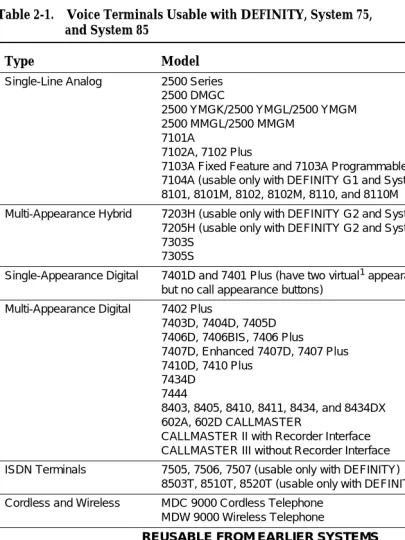
This part explains higher level topics that apply to voice terminals as a group and contains descriptions of facilities and characteristics that are common to all or most terminals. Table 2-1 presents a summary of all voice terminals used with a DEFINITY G1, G2, and G3, a DEFINITY ECS, System 75, and System 85.
The complete line of voice terminals are two basic types, single-line voice terminals and multi-appearance voice terminals. The operational differences between these types are in the way they access features and the way they receive calls.
Single-Line Voice Terminals
Terminals and Adjuncts Reference Manual December 1996 General Information
Page 2-2 Voice Terminals
2
alerts the user via a “call waiting tone” (in the handset or speakerphone) that a call is waiting to be answered. While a single-line terminal is occupied with two calls, any other calls placed to the terminal get a busy tone.
All single-line voice terminals are analog in operation; that is, transmission of all signals between the terminal and its port, at the system digital switch, is in analog form over a tip and ring pair of wires. The port circuit provides analog/digital signal conversion. Power for these terminals is supplied from the switch on the single voice pair. Single-line terminals have many applications but are more limited in their access to system features than multi-appearance terminals.
Multi-Appearance Voice Terminals
A multi-appearance voice terminal gives its user much more flexibility in handling calls than a single-line voice terminal. A multi-appearance voice terminal,
represented by a unique primary extension number, has multiple call
appearances (buttons with lights) where incoming calls to the number can be answered and outgoing calls can be originated. Incoming calls can ring
simultaneously at all appearances except for those translated as originate-only. As long as at least one appearance is idle, callers will not receive busy tone. When all call appearances, except call appearances translated as originate-only, are busy, callers will hear busy tone unless the incoming call is a priority call or the Restrict Last Appearance feature is deactivated. The terminal user must decide the order to answer multiple incoming calls.
The two sub-types of multi-appearance voice terminals are digital and hybrid. Digital terminals generate and receive voice and control signals in digital form. Connection between terminals and the system switch is over 2-pair digital links; no conversion is necessary at the digital line port. Hybrid terminals, as the name implies, combine analog and digital. They are connected to the system switch by three pairs of links; on MET-like hybrid sets, one pair is for analog voice, and the other two pairs are for digital control signals, and on ATL-like hybrid sets, one pair is for digital control signals, and the other two pairs are for analog voice. DC power for all multi-appearance terminals (except for the 7404D and 7407D01B, which are AC powered) is conducted from the switch over the digital pairs.
Digital multi-appearance voice terminals have several important advantages over hybrids:
■ Digital voice terminals can support and control data terminals. ■ The Digital Communications Protocol (DCP) or ISDN-BRI interface
between a digital voice terminal and the system switch supports
simultaneous voice and data calls over the terminal’s standard mounting cord.
■ Digital terminals have a wider selection of adjuncts.
DEFINITY Enterprise Communications Server and System 75 and System 85 Terminals and Adjuncts Reference Manual
Issue 8 December 1996 General Information
Page 2-3 Voice Terminals
2
1. The word “virtual” refers to the fact that there are no call appearance buttons associated with either appearance. Refer to the description of the 7401D and 7401 Plus Voice Terminal for more information.
Table 2-1. Voice Terminals Usable with DEFINITY, System 75, and System 85
Type Model
Single-Line Analog 2500 Series
2500 DMGC
2500 YMGK/2500 YMGL/2500 YMGM 2500 MMGL/2500 MMGM
7101A
7102A, 7102 Plus
7103A Fixed Feature and 7103A Programmable 7104A (usable only with DEFINITY G1 and System 75) 8101, 8101M, 8102, 8102M, 8110, and 8110M
Multi-Appearance Hybrid 7203H (usable only with DEFINITY G2 and System 85) 7205H (usable only with DEFINITY G2 and System 85) 7303S
7305S
Single-Appearance Digital 7401D and 7401 Plus (have two virtual1 appearances, but no call appearance buttons)
Multi-Appearance Digital 7402 Plus
7403D, 7404D, 7405D 7406D, 7406BIS, 7406 Plus
7407D, Enhanced 7407D, 7407 Plus 7410D, 7410 Plus
7434D 7444
8403, 8405, 8410, 8411, 8434, and 8434DX 602A, 602D CALLMASTER
CALLMASTER II with Recorder Interface CALLMASTER III without Recorder Interface
ISDN Terminals 7505, 7506, 7507 (usable only with DEFINITY)
8503T, 8510T, 8520T (usable only with DEFINITY G2 and G3)
Cordless and Wireless MDC 9000 Cordless Telephone
MDW 9000 Wireless Telephone
REUSABLE FROM EARLIER SYSTEMS
Single-Line Analog 500 (can also be ordered new)
2500 Series (can also be ordered new) Multi-Appearance Hybrid
(MERLIN)
7305H 7305H01B 7305H02B Multi-Button Electronic
Telephone (MET) Sets
10 Button with or without Built-In Speakerphone 20 Button
30 Button
Terminals and Adjuncts Reference Manual December 1996 General Information
Page 2-4 Voice Terminals
2
Facilities Common to All Voice Terminals
Every DEFINITY G1, G2, and G3, DEFINITY ECS, System 75, and System 85 voice terminal has the following equipment:
■ A pushbutton pad for touch-tone dialing (except for the Model 500, which
has a rotary dial).
■ A handset with a coiled modular cord.
■ A 7-foot modular mounting cord (except for the Model 2554 wall set).
Buttons
All multi-appearance voice terminals and most single-line terminals have buttons for handling calls and activating various functions that enhance basic calling.
Fixed Feature Buttons
Buttons that are factory labeled and require no administration are referred to as fixed feature buttons. The following buttons, in several combinations, are found on most voice terminals. They are dedicated to standard calling functions and are located adjacent to or above the pushbutton dial pad for calling convenience.
NOTE:
Fixed feature buttons that are limited to a small number of terminals are explained in the detailed descriptions of those terminals.
■ Recall Button (on older sets)—provides a timed flash that is more accurate
than a manual switchhook flash and prevents accidental dropping of calls. The following list of uses for this button is only valid for single-line
terminals:
— Put an active call on hold and obtain recall dial tone for making another call.
— Disconnect from a second call and return to a call on hold, when pressed twice.
— Place an active call on hold and answer a waiting call using Dial Access Code, then toggle between the two calls (using the Recall button and Dial Access Code).
— Place an active call on hold; receive recall dial tone, and dial the Feature Access Code to answer a waiting call. Toggle between the two calls by performing the same action.
— Add a party, previously put on hold, to a conference with a third party.
DEFINITY Enterprise Communications Server and System 75 and System 85 Terminals and Adjuncts Reference Manual
Issue 8 December 1996 General Information
Page 2-5 Voice Terminals
2
■ Disconnect Button (on older sets)—allows the terminal user, after
completing one call, to permanently disconnect from the call and get dial tone for placing a new call without going on- and off-hook. On System 85 and DEFINITY G2, depending on the administration, this button can be used to reconnect to the call on hold on multiple appearance voice terminals.
■ Hold Button—is used to temporarily disconnect from one call, without
dropping it, so that another call can be answered or originated. The user can return to the call on hold.
■ Drop Button—is used to permanently disconnect the last party added to a
conference call. On System 85 and DEFINITY G2, this button also gives dial tone on the same call appearance if dialing or on a 2-party call.
NOTE:
On some voice terminals, this button is also used to perform a test of the voice terminal’s lights, ringer, and display (if the terminal has one).
■ Conference Button—enables the terminal user to set up a conference call
by adding new calls to an existing 2-party connection. The user can add as many as five calls to a conference. (On System 85 and DEFINITY G2 the user can only build a 3-party conference call using this button; 6-party conference calls can be built by the attendant.)
NOTE:
On some voice terminals, this button is also used to select a personalized ring from 8 available ringing patterns.
■ Transfer Button—enables the terminal user to shift an active call to
another voice terminal.
■ Select Ring Button (on older sets)—enables the terminal user to select a
personalized ringing pattern.
■ Speaker Button—turns on either a listen-only speaker or a 2-way
speakerphone which allows the user to speak and listen to the far-end party.
NOTE:
On some voice terminals, this button also allows the user to initiate an acoustic test of the surrounding environment (the Reset
Speakerphone feature) through a series of tones. When the tones stop, the speakerphone has finished adjusting itself for optimal performance.
■ Mute Button—turns off the microphone of the built-in speakerphone or the
Terminals and Adjuncts Reference Manual December 1996 General Information
Page 2-6 Voice Terminals
2
Administrable Buttons
Buttons that are not fixed feature buttons are administered (or assigned) by the System Manager or the terminal user for many functions. Buttons that may be administered include call appearance/feature buttons and feature-only buttons.
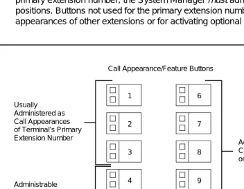
Every multi-appearance voice terminal has a minimum of three buttons while others have as many as 34 buttons that can be administered as call appearances, that is, positions for answering incoming calls and originating outgoing calls (see
Figure 2-1). In DEFINITY G1, G3, and System 75, software defaults the first three of these buttons for appearances of the terminal’s primary (or home) extension number; the System Manager has the option of administering Button #3 differently. In DEFINITY G2 and System 85, no buttons are defaulted for the primary extension number; the System Manager must administer all the required positions. Buttons not used for the primary extension number can be assigned as appearances of other extensions or for activating optional features.
Figure 2-1. Call Appearance/Feature Buttons
Associated with each call appearance/feature button is a pair of lights that provide information on the availability and status of the appearance. These lights are described in the next part of this manual (titled ‘‘Lights”).
Any button that can be administered and is not used for a call appearance can be assigned to an optional feature. Included in this category are buttons with two
1 Usually
2
3
4
5 Administered as
Call Appearances of Terminal’s Primary Extension Number
Administrable as Call Appearances or Features
Call Appearance/Feature Buttons
6
7
8
9
10
Administrable as Call Appearances or Features
DEFINITY Enterprise Communications Server and System 75 and System 85 Terminals and Adjuncts Reference Manual
Issue 8 December 1996 General Information
Page 2-7 Voice Terminals
2
lights (call appearance/feature buttons) and buttons with one or no lights, intended specifically for features. Some features require light feedback to inform the terminal user when the feature is active; others are simple, one-time
operations for which light feedback would be meaningless. Good feature administration matches features to appropriate buttons whenever possible.
Lights
Indicator lights provide silent visual reminders to the voice terminal user regarding lines, features, and messages taken at other locations. The lights on voice terminals connected to a DEFINITY G1, G2, and G3, a DEFINITY ECS, System 75, or System 85 are light-emitting diodes (LEDs) or neon lights.
On all multi-appearance voice terminals, each call appearance/feature button has two indicator lights: a red light and a green status light. When a call
appearance/feature button is used for a feature, only the status light is
operational; the red light remains off at all times. Feature-only buttons have either a single green status light or no light at all. The various arrangements of red and green lights are shown inFigure 2-2.
Figure 2-2. Button Lights
Red Light
Green Status Light Green Status Light
Green Status Light Red Light
Two Styles of Light Arrangement for Call Appearance/Feature Buttons
Green Status Light
Terminals and Adjuncts Reference Manual December 1996 General Information
Page 2-8 Voice Terminals
2
Red Light
The red light normally has two states: lighted steadily or dark (off).
NOTE:
On the ISDN-BRI 7505, 7506, and 7507 sets, the red light flashes when the set is using phantom power.
One red light is always on at a multi-appearance voice terminal when the handset is on hook. It identifies the call appearance the user will be automatically
connected to if the handset is lifted. When the handset is lifted, the red light identifies the call appearance that is active.
The red light is off when the handset is lifted but not connected to a call appearance. For example, when one call has been put on hold but another call appearance button has not been pressed. When certain features such as Preselection, Idle Line Originating preference, or No Line Originating Preference are administered, the red light is also off while on hook.
Green Status Light
The green status light can indicate any one of the following six conditions:
■ Off—the call appearance is idle or the assigned feature is not activated. ■ Lighted steadily—the call appearance is busy or the assigned feature is
active.
■ Flashing (slow on-off for equal periods, one cycle per second)—an
unanswered incoming call on that call appearance.
■ Fluttering (fast on-off for equal periods, 10 cycles per second)—a call
placed on hold on that call appearance by the voice terminal user.
■ Broken Fluttering (fast on-off modulated at the slow rate)—feature denial to
the calling voice terminal or an unknown or invalid action.
■ Winking (long on-short off at about three cycles per second)—a call placed
on hold from another voice terminal or an action pending.
Message Light
DEFINITY Enterprise Communications Server and System 75 and System 85 Terminals and Adjuncts Reference Manual
Issue 8 December 1996 General Information
Page 2-9 Voice Terminals
2
Tones
The tones that a voice terminal user hears can be divided into two categories:
■ Ringing Tones—those that are generated in the base of the voice terminal
and can be heard in the surrounding area; they indicate incoming calls.
■ Handset Tones—those that are transmitted through the handset and heard
only by the user or through the speakerphone when it is turned on.
External Ringing Tones
Ringing tones are the only tones heard outside the voice terminal when it is receiving a call. This signal cycles in 1-, 2-, or 3-ring patterns. On System 75 and DEFINITY G1 and G3, only one cycle of ringing is heard if the multi-appearance voice terminal is busy with another call. On System 85 and DEFINITY G2, the cycling repeats (except on the ISDN 7500-series sets).
■ One ring—a call from another voice terminal in the system ■ Two rings—a call from the attendant or outside caller
■ Three rings—priority calls, for example, Automatic Callback, Priority
Calling, or Ringback from a queued call
■ One short unmodulated tone—an intercom call
■ Ring-Ping (half ring)—a call redirected away from the voice terminal
because Send All Calls or Call Forwarding is active; also called coverage tone.
■ On System 85 and DEFINITY G2, any of these external tones, plus a
repeated unmodulated tone, may be administered to indicate an intercom call.
Handset Tones
The following tones are heard through the handset:
■ Answer Tone—a high-pitched continuous tone indicating that a data
endpoint has answered.
■ Busy Tone—a low-pitched tone repeated 60 times a minute; indicates that
the number dialed is in use.
■ Call Waiting Tone (Single-Line Voice Terminals)—one, two, or three
beeps (short bursts of high-pitched tone), not repeated; indicates to the user at a busy single-line terminal that an incoming call is waiting to be answered. The number of beeps indicates the source of the waiting call:
— One beep—a call from another voice terminal in the system
— Two fast beeps—a call from the attendant or an outside caller
Terminals and Adjuncts Reference Manual December 1996 General Information
Page 2-10 Voice Terminals
2
■ Confirmation Tone—(three short bursts of tone) indicates that a feature
activation or cancellation has been accepted, or that an outgoing call from a single-line voice terminal has been placed in a ringback queue.
■ Coverage Tone—(one long burst of tone) indicates to the calling party that
a call to an extension number will be answered at another extension number by a covering user.
■ Dial Tone—(a continuous steady tone) indicates that dialing or feature
activation can begin.
■ Intercept Tone—(an alternating high and low tone) indicates either a
dialing error or a denial of the service requested.
■ Recall Dial Tone—(three short bursts of dial tone followed by steady dial
tone) indicates that the feature requested has been accepted and dialing can start.
■ Recorded Telephone Dictation Ready Tone—(a high-pitched continuous
tone) indicates that a dictation machine has been connected to the voice terminal.
■ Reorder Tone—(a fast-busy tone repeated 120 times a minute) indicates
that all outgoing trunks are busy or feature resource is not available. Try again.
■ Ringback Tone—(a low-pitched tone repeated 15 times a minute)
indicates to the calling party that the number dialed has been reached successfully and is ringing.
■ Ringback Tone, Call Waiting—(a ringback tone with a short lower-pitched
signal at the end) indicates to the calling party that the extension called is busy, but that the called party has been given the call waiting signal.
■ Time-Out Tone—[an alternating high and low tone (same as intercept
tone)] indicates a failure to dial within a preset interval (usually 10 seconds) after lifting the handset or after dialing the previous digit.
■ Warning Tone (Bridging)—(a low-pitched tone heard by all parties in a
Busy Verification attempt that bridges on to an active call) initially applied in a 2-second (System 75 and G1) or 4-second (System 85 and G2) burst, then in half-second bursts every 15 seconds.
Desk/Wall Mounting Arrangements
DEFINITY Enterprise Communications Server and System 75 and System 85 Terminals and Adjuncts Reference Manual
Issue 8 December 1996 General Information
Page 2-11 Adjuncts
2
Adjuncts
Adjuncts are optional devices that extend the existing capabilities of voice terminals or provide new services. Some adjuncts are physically attached to their voice terminals, and others are free-standing, connected by way of mounting cords. The adjuncts have styling and colors that are compatible with the associated voice terminals.
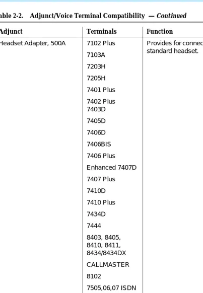
Figure 2-2 provides a cross-reference between adjuncts and the voice terminals with which they are used. The following limitations apply to the use of multiple adjuncts:
■ A speakerphone and a headset adapter cannot be connected to the same
voice terminal simultaneously because they plug into the same jack on the terminal.
■ A C401A Call Coverage Module and a D401A Digital Display Module
cannot be mounted on the same 7405D or 7434D Voice Terminal simultaneously because they attach to the same part of the terminal.
None of the adjuncts have facilities for wall mounting, and wall-mounting kits are not available. However, the modules (call coverage, function key, and digital display) are attached to their voice terminals, which can then be mounted on a wall. Free-standing adjuncts (speakerphones and headset adapters) associated with wall-mounted terminals can be placed on a nearby shelf or table.
Table 2-2. Adjunct/Voice Terminal Compatibility
Adjunct Terminals Function
Call Coverage Module, C201A
7205H Adds 20 call appearance/ feature
buttons.
Call Coverage Module, C401A
7405D 7434D
Call Coverage Module, C401B
7405D 7434D
Digital Display Module, D401A
7405D
7434D Displays call-related and personal
service information. Digital Display Module,
D401B
7405D 7434D
Function Key Module, F201A
7205H
Adds 24 feature buttons. Function Key Module,
F401A
Terminals and Adjuncts Reference Manual December 1996 General Information
Page 2-12 Adjuncts
2
Headset Adapter, 500A 7102 Plus
7103A
7203H
7205H
7401 Plus
7402 Plus 7403D
7405D
7406D
7406BIS
7406 Plus
Enhanced 7407D
7407 Plus
7410D
7410 Plus
7434D
7444
8403, 8405, 8410, 8411, 8434/8434DX
CALLMASTER
8102
7505,06,07 ISDN
8503T ISDN
8510T ISDN
8520T ISDN
515 BCT
Provides for connection and control of standard headset.
Headset Adapter, 502A 7303S
7305S
Provides for connection and control of standard headset.
Message Waiting Indicator, Z34A
2500 Indicates that a message has been
left for the terminal.
Table 2-2. Adjunct/Voice Terminal Compatibility — Continued
DEFINITY Enterprise Communications Server and System 75 and System 85 Terminals and Adjuncts Reference Manual
Issue 8 December 1996 General Information Page 2-13 Data Modules 2
Several power supplies and connection schemes are available for providing auxiliary adjunct power when it is required. Refer to the Chapter 5, ‘‘Adjunct Power’’ section of this manual for more information on these power sources.
Data Modules
Data modules provide an interface between the system’s digital switch and Data Terminal Equipment (DTE) or Data Communications Equipment (DCE). DTE is defined as a data source or a data link or a combination of both; typical examples are data terminals and host computers. DCE is equipment that provides the functions for establishing, maintaining, and terminating a data call; a modem is an example of DCE.
An interface device between the switch and DTE or DCE is necessary because the set of data transmission rules and formats—the data protocol—at the switch is different from the protocol at the DTE or DCE. The digital ports of the switch present a DCP or ISDN-BRI interface to all devices connected to them. DCP supports simultaneous voice and data communications by multiplexing the two sets of signals into one digital stream. Digital voice terminals and some data terminals can be connected directly to the switch. But, if a data endpoint has a different protocol (EIA RS-232C or RS-232D is the most common) than the switch, a data module must be inserted to provide compatibility. The data module
Messaging Cartridge 7404D Provides display of call-related and
personal service information on data terminal screen.
PC/PBX Plug-in Cartridge 7404D Provides interface with PCs.
Speakerphone, S101A
Speakerphone, S201A
Same as 500A
Headset Adapter
Provides hands-free calling.
Speakerphone, S102A
Speakerphone, S202A
Same as 502A
Headset Adapter
Provides hands-free calling.
Provides improved voice quality by adapting to room acoustics.
Speakerphone, 4A Speakerphone, 203A Loudspeaker, 107 2500 Analog or stand-alone 2500
Provides hands-free calling.
Provides hands-free answering. Provides hands-free calling when not used as stand-alone.
Provides amplification for the received voice signal.
Automatic Dialer, 2870A1 MET Provides the capability to record and
automatically dial 31 numbers.
Table 2-2. Adjunct/Voice Terminal Compatibility — Continued
Terminals and Adjuncts Reference Manual December 1996 General Information
Page 2-14 Data Modules
2
provides the two-way data signal conversion and processing required between different protocols. Figure 2-3 shows a simplified diagram of the components of a typical data link.
Figure 2-3. Data Link Components
The connection between a data module and a data endpoint must always have a DCE or DTE interface. If the endpoint is a DCE, the data module must present a DTE interface to it. If the endpoint is a DTE, then the data module must present a DCE interface. In general, modules are classified as DCE- or DTE-type according to the kind of data endpoint to which they are connected.
Data modules are available to match a wide variety of data needs:
■ Asynchronous operation at data rates from 0.3-19.2 kbps and even, odd,
mark/space, zero/one or no parity options.
■ Synchronous operation at data rates of 0.3, 1.2, 2.4, 4.8, 9.6, 19.2, 56, and
64 kbps.
■ Half- or full-duplex operation and internal or external timing options at the
appropriate data rates.
The following data equipment is available with a DEFINITY G1, G2, and G3, a DEFINITY ECS, System 75, and System 85:
■ 7400A Data Module — In DTE mode, works with asynchronous DCE in
the modem pool at data rates of 0.3-19.2 kbps, full-duplex. Supports both Hayes-compatible and D-lead modems. In DCE mode, the 7400A has Hayes®, Keyboard Dial or Answer-Only interface. Also works with asynchronous DTE where rack mounting is needed. Takes the place of MTDM or MPDM in asynchronous applications.
■ 7400B and 7400B Plus Data Modules — Works with asynchronous DTE
at data rates of 0.3-19.2 kbps, full-duplex. Can be used with most 7400-series DCP voice terminals for simultaneous voice/data or
Data Endpoint
Data Module
Data Module
Data Endpoint DEFINITY
G1, G2, G3 System 75
or System 85
Digital Switch RS-232C/D
V.35 RS-449
DCP RS-232C/D
DEFINITY Enterprise Communications Server and System 75 and System 85 Terminals and Adjuncts Reference Manual
Issue 8 December 1996 General Information
Page 2-15 Data Modules
2
stand-alone. Emulates a Hayes-compatible modem, therefore, can be used with standard PC communications packages. Takes the place of previous DCP asynchronous data stands.
■ 7400D Data Module — Works as a DCE device between a DTE and the
PBX. A DTE configuration (that is, modem pooling) is not supported, and the DCE configuration is limited to an Answer-Only-type interface option. Dates rates range from 0.3 to 19.2 kbps.
■ 8400B Plus — Works as a data service link between a DTE device, a
2-wire voice terminal such as the 8400-Series voice terminals, and a DEFINITY G3V2 or later. At the desk, the 8400B Plus data module provides asynchronous communication speeds ranging from 0.3 to 19.2 kbps.
■ Modular Processor Data Module (MPDM) — Works with synchronous
DTE at data rates of 0.3-64 kbps. Also works at full- or half-duplex with internal or external timing at the appropriate data rates. Supports V.35, RS-232, and RS-449 interfaces and RS-366 Automatic Calling Unit interface at the previously mentioned rates. Video codes are an example of 56 or 64 kbps endpoints where calls are set up via the RS-366 interface. The MPDM also supports asynchronous applications, but the 7400B Plus supersedes it for applications requiring Hayes emulation and the 7400A supersedes it for remaining asynchronous applications.
■ Modular Trunk Data Module (MTDM) — Works with a synchronous DCE
in modem pool applications at data rates of 0.3-19.2 kbps. Also works at full- or half-duplex with internal or external timing at the appropriate synchronous data rates. The 7400A supersedes it for asynchronous applications.
■ 7500B Data Module — Works with asynchronous or synchronous DCE or
DTE on BRI switch interface (DEFINITY G2 or 5ESS® switch only). Supports RS-232 and V.35 interfaces and RS-366 Automatic Calling Unit interface (for the RS-232 interface only).
■ ISDN Asynchronous Data Module (ADM) — Works with asynchronous
DTE as a data stand for 7500-series BRI phones (DEFINITY G2 and 5ESS switch only). Supports Hayes command set for compatibility with
PC communications packages.
■ DEFINITY High Speed Link — Works with synchronous V.35 DTE at data
rates of 56 kbps half or full duplex or 64 Kbps full duplex. Supports Permanent (private line type) calls and switched calls. Switched calls can be set up using either the RS-366 or RS-232 (Hayes ATD command) interface; via DTR or Hotline dialing; or manually using the front panel call control feature. Replaces the ACCUNET MPDM for video, LAN, CC/FEP and other high speed applications.
■ Asynchronous Data Unit (ADU) — Works with asynchronous DTE at
Terminals and Adjuncts Reference Manual December 1996 General Information
Page 2-16 PC Platform Products
2
opposed to PCs. Connects to SN 238 (System 85 and DEFINITY G2 traditional modules) or TN726 (System 75 and DEFINITY G1 and G2 universal modules).
■ Multiple Asynchronous Data Unit (MADU) — Works with asynchronous
DTE at data rates of 0.3-19.2 kbps in host applications. The MADU is rack-mounted and supports busy-out. It connects to the same switch ports as the ADU.
■ 2500-Series Data Service Unit (DSU), Isolating Data Interface (IDI), and
Local Distribution Service Unit (LDSU) — DCIU interface units for DEFINITY G2 and System 85.
PC Platform Products
PC/PBX Platform — PC expansion cards and software for XT/AT bus and MicroChannelTM bus PCs in the DCP environment. Supports common,
open data interface with PC/ISDN platform. Supported software includes PC/PBX Connection (for advanced phone management, access to synchronous and asynchronous hosts, and high-speed PC-to-PC communication) and E78 Plus. Works with any 7400-series phone.
PC/ISDN Platform — PC expansion card and software for XT/AT bus PCs in the BRI environment (DEFINITY G2 and 5ESS). Supports common, open data application interface with PC/PBX Platform. Supported software includes E78 Plus and high-speed PC-to-PC file transfer applications.
E78 Plus/ISDN — Software written to the open data applications interface which provides full 3270 terminal emulation and fast file transfer in IBM environments.
3270 Data Module — The 3270C Data module connects to an IBM® 3274
or 3174 Cluster Controller and converts DCP data from the PC platform products to the IBM Coax A format to access IBM mainframes for 3270 terminal emulation and fast file transfer.
The above PC platform products allow PC users to:
— Dial calls from the PC and use customized phone features from the keyboard, including a personalized phone directory, log of calls received and made, note-taking on calls, and phone message retrieval.
— Connect to a variety of asynchronous hosts and to IBM mainframes, allowing file transfer to and from the mainframe using standard IBM file transfer protocols and the standard DCA IRMA board user interface.
— Transfer files from PC to PC at rates up to 1.2 kbps over a 64 kbps facility using a PC package from Hilgraeve, Inc.
DEFINITY Enterprise Communications Server and System 75 and System 85 Terminals and Adjuncts Reference Manual
Issue 8 December 1996 General Information
Page 2-17 Data Terminals
2
Data Terminals
A data terminal is a workstation at which data is entered and retrieved; it communicates through lines, trunks, switches, and data modules with data endpoints such as computers and other data terminals. Some data terminals contain built-in voice capabilities similar to digital voice terminals. For detailed information on buttons, lights, and tones, refer to the general information about voice terminals at beginning of this section.
The following data terminals are available with System 75, System 85, and DEFINITY G1 and G2:
■ AT&T Personal Terminal 510A (no longer manufactured)(DA) ■ AT&T Personal Terminal 510D (no longer manufactured)(DA) ■ Model 513 Business Communications Terminal (BCT) (no longer
manufactured)(DA)
■ Model 515 BCT (no longer manufactured)(DA)
■ Model 610 BCT
■ Model 615 MT
The 513 BCT, 610 BCT, and 615 MT, in addition to being optional units of peripheral equipment, are used in DEFINITY G1 and System 75 as System Access Terminals (SATs). The SAT is dedicated to system administration and maintenance and is located in or nearby the equipment room with the DEFINITY G1 or System 75. This manual does not cover the 513, 610, or 615 as an SAT but only as peripheral data terminals used for sending and receiving data calls.
Technical Specifications
Terminals and Adjuncts Reference Manual December 1996 General Information
Page 2-18 Technical Specifications
2
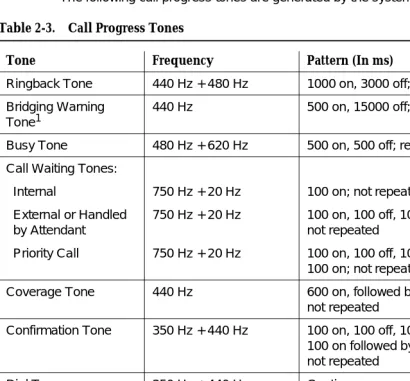
Call Progress Tones
The following call progress tones are generated by the system:
1. This tone is used with the Busy Verification and Executive Override features and Service Observing when the warning tone is enabled.
Table 2-3. Call Progress Tones
Tone Frequency Pattern (In ms)
Ringback Tone 440 Hz + 480 Hz 1000 on, 3000 off; repeated
Bridging Warning Tone1
440 Hz 500 on, 15000 off; repeated
Busy Tone 480 Hz + 620 Hz 500 on, 500 off; repeated
Call Waiting Tones:
Internal
External or Handled by Attendant
Priority Call
750 Hz + 20 Hz
750 Hz + 20 Hz
750 Hz + 20 Hz
100 on; not repeated
100 on, 100 off, 100 on; not repeated
100 on, 100 off, 100 on,100 off, 100 on; not repeated
Coverage Tone 440 Hz 600 on, followed by silence;
not repeated
Confirmation Tone 350 Hz + 440 Hz 100 on, 100 off, 100 on,100 off,
100 on followed by silence; not repeated
Dial Tone 350 Hz + 440 Hz Continuous
Intercept Tone 480 Hz & 620 Hz 250 on (480 Hz), 250 on (620 Hz);
repeated
Reorder Tone 480 Hz + 620 Hz 250 on, 250 off; repeated
Call Waiting Ringback Tone
440 Hz + 480 Hz;
440 Hz
1000 on (440 Hz + 480 Hz),
DEFINITY Enterprise Communications Server and System 75 and System 85 Terminals and Adjuncts Reference Manual
Issue 8 December 1996 General Information
Page 2-19 Technical Specifications
2
External Ringing Tones
The following external ringing tone patterns are generated by the system:
For most currently available voice terminals, the user can select a Personalized Ringing pattern (out of eight possible ringing patterns). The tone patterns are the same as those previously described. The three tones are 530 Hz [low (L)], 750 Hz [medium (M)], and 1060 Hz [high (H)]. The tone sequences are as follows: (Each of these sequences is prefaced by a medium level tone.)
Table 2-4. External Ringing Tone Patterns
Ringing Tone Pattern (In ms)
1 1200 on, 4000 off; repeated
2 400 on, 200 off, 600 on, 4000 off; repeated
3 200 on, 100 off, 200 on, 100 off, 600 on,
4000 off; repeated
Table 2-5. The Eight Personalized Ringing Patterns
Ring Pattern Tone Sequence
1 MMM
2 HHH
3 LLL
4 LHH
5 HHL
6 HLL
7 HLH
Terminals and Adjuncts Reference Manual December 1996 General Information
Page 2-20 Technical Specifications
2
Indicator Lights Signals
The following light signals are generated by the system for the attendant console and multi-appearance voice terminals:
Table 2-6. Indicator Lights Signals
Lamp Signal Pattern (In ms)
Dark (Off) Off
Lighted (On) On
Flashing 500 on, 500 off; repeated
Fluttering 50 on, 50 off; repeated
Broken Flutter 5 cycles of 50 on, 50 off, followed by 500 off; repeated
Exposed Port Protection
Page 3-1 Out-of-Building Campus Stations
3
DEFINITY Enterprise Communications Server and System 75 and System 85 Terminals and Adjuncts Reference Manual 555-015-201
Issue 8 December 1996
3
3Exposed Port Protection
All port packs and terminals require unique protection and grounding arrangements as defined in the checklists (System 75 Electrical Protection, Grounding, and Exposure Checklist, 555-200-120 and System 85 Electrical Protection, Grounding, and Exposure Checklist, 555-103-120). These
arrangements provide an adequate barrier to the potentially damaging voltages and currents inherent in lightning and power surges present in exposed
applications. Moreover, the National Electrical Code requires that an approved protector be provided on all exposed circuits.
Ports and terminals that utilize facilities that are subject to disturbances from lightning, ground potential rises (GPR), or possible contact or induction from electrical power sources or circuits in excess of 300 volts (RMS) to ground are classified as exposed. Any ports or terminals served by such exposed facilities are classified as exposed and require protection at both the port and terminal ends. The checklists contain flowcharts that are beneficial in determining exposure status and tables to determine the type of protector required.
Out-of-Building Campus Stations
An out-of-building campus station is a telephone or voice terminal that is not physically located in the same building as the equipment room, but is located on the same property. Both analog telephones and digital voice terminals can be used as out-of-building stations.
Terminals and Adjuncts Reference Manual December 1996 Exposed Port Protection
Page 3-2 Out-of-Building Campus Stations
3
Protection is required at both entrances for digital out-of-building voice terminals. There are two different types of protectors that can be used to protect digital voice terminals and digital line circuit packs in an out-of-building environment: the 4C3S-75 Enhanced Protector and the ITW Linx Enhanced Protector.
NOTE:
The 4C3S-75 Enhanced Protector may only be used on Vintage 14 or newer TN754 Circuit Packs. The 4C3S-75 can be used on all vintages of the TN754B Circuit Pack. The ITW Linx Enhanced Protector may be used on all Vintages of the TN754 and TN754B Circuit Packs.
The 4C3S-75 Enhanced Protector is equipped with a heat coil for sneak current protection and the ITW Linx Enhanced Protector is equipped with replaceable fuses for sneak current protection.
DEFINITY Enterprise Communications Server and System 75 and System 85 Terminals and Adjuncts Reference Manual
Issue 8 December 1996 Exposed Port Protection
Page 3-3 Recommended Protectors and IROB Protection
3
Recommended Protectors and IROB
Protection
Table 3-1 shows the recommended protectors for the DEFINITY G1, G2, and G3, DEFINITY ECS, System 75, and System 85. Table 3-2 shows the in-range, out-of-building (IROB) protection for DEFINITY line circuits and terminals.
!
CAUTION:
The following circuit pack and terminal arrangements are not allowed to be installed in an exposed environment:
1. 7300 Series connected to the TN762B or ANN17 Circuit Pack
2. MET terminals connected to the TN735 Circuit Pack
3. Analog terminals connected to the TN746 Circuit Pack
Table 3-1. Recommended Protectors
Primary
Primary
(with Heat Coil) Enhanced Primary Secondary
3B1A (carbon)
4B1C (carbon)
4C3S-75 (solid state)
79A Fuse
3B1E-W
(wide-gap gas tube)
4B1E-W
(wide-gap gas tube)
ITW Linx
(gas tube avalanche suppress)
SCP-1
3C1S (solid state)
Terminals and Adjuncts Reference Manual December 1996 Exposed Port Protection
Page 3-4 Recommended Protectors and IROB Protection
3
* Key to Abbreviations:
P = Primary; EP = Enhanced Primary
Notes:
1. Primary protection with heat coils for sneak protection are coded with the number 4 as the first numeric. DEFINITY ports require sneak current protection for IROB terminal installations. 2. The TN754, V1 through V13 may be installed with either the DLP and primary protector or the
ITW Linx Enhanced Primary protector. These vintages may not be installed with the 4C3S-75 Enhanced Primary protector.
3. The 4C3S-75 Enhanced Protector may only be used on Vintage 14 or newer TN754 Circuit Packs. The ITW Linx Enhanced Protector may be used on all Vintages of the TN754 Circuit Pack.
4. The TN556 Circuit Pack requires Enhanced Primary protection at the port and Primary (3- or 4-type) protection at the terminal.
For more information on exposed port protection, refer to:
■ DEFINITY Communications System Generic 1 and Generic 3 Wiring,
555-204-111
■ DEFINITY Communications System Generic 2 and System 85 Wiring,
555-104-630
Table 3-2. IROB Protection
Circuit Packs Terminal Required Protector*
SN224 7203,
7205,
MET
EP
SN228B,
SN229
2500 Series,
2500DMGC,
7100 Series
P1
TN742,
TN746B,
TN769
500 Series,
2500 Series,
7100 Series
P1
SN270 7400 Series EP
TN754 7400 Series (ITW)2
TN754, V14 7400 Series EP3
Availability
Page 4-1
4
DEFINITY Enterprise Communications Server and System 75 and System 85 Terminals and Adjuncts Reference Manual 555-015-201
Issue 8 December 1996
4
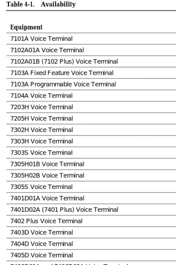
4Availability
This section provides the availability of the products described in this manual. The availability of these products is constantly changing as new products and different versions of existing products are introduced. The status of some of the products in this list may have changed since this manual was issued. Check the Sales Manual for the final determination of the equipment status.
The following convention is used in Table 4-1:
■ DA — Discontinued Availability
■ GA — General Availability
Terminals and Adjuncts Reference Manual December 1996 Availability
Page 4-2
4
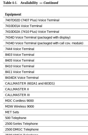
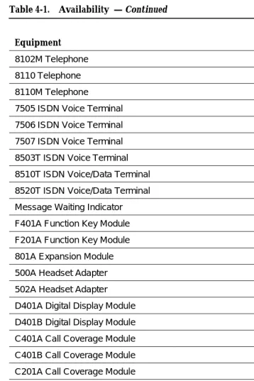
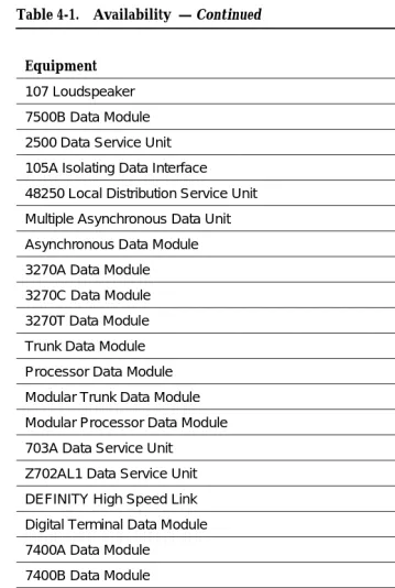
Table 4-1. Availability
Equipment
Ordering Status
7101A Voice Terminal DA
7102A01A Voice Terminal LA
7102A01B (7102 Plus) Voice Terminal LA
7103A Fixed Feature Voice Terminal DA
7103A Programmable Voice Terminal DA
7104A Voice Terminal DA
7203H Voice Terminal DA
7205H Voice Terminal DA
7302H Voice Terminal DA
7303H Voice Terminal DA
7303S Voice Terminal DA
7305H01B Voice Terminal DA
7305H02B Voice Terminal DA
7305S Voice Terminal DA
7401D01A Voice Terminal DA
7401D02A (7401 Plus) Voice Terminal DA
7402 Plus Voice Terminal DA
7403D Voice Terminal DA
7404D Voice Terminal DA
7405D Voice Terminal DA
7406D01A and 7406D02A Voice Terminal DA
7406D03A and 7406D04A Voice Terminal DA
7406D06A (7406BIS) Voice Terminal DA
7406D05A (7406BIS) Voice Terminal w/display DA
7406D08A (7406 Plus) Voice Terminal DA
7406D07A (7406 Plus) Voice Terminal w/display GA
7407D01B Voice Terminal DA
7407D02C (Enhanced 7407D) Voice Terminal DA
DEFINITY Enterprise Communications Server and System 75 and System 85 Terminals and Adjuncts Reference Manual
Issue 8 December 1996 Availability
Page 4-3
4
7407D02D (7407 Plus) Voice Terminal GA
7410D01A Voice Terminal DA
7410D02A (7410 Plus) Voice Terminal GA
7434D Voice Terminal (packaged with display) DA
7434D Voice Terminal (packaged with call cov. module) GA
7444 Voice Terminal GA
8403 Voice Terminal GA
8405 Voice Terminal GA
8410 Voice Terminal GA
8411 Voice Terminal GA
8434DX Voice Terminal GA
CALLMASTER (602A1 and 603D1) LA
CALLMASTER II GA
CALLMASTER III GA
MDC Cordless 9000 GA
MDW Wireless 9000 GA
MET Sets LA
500 Telephone GA
2500 Series Telephone DA
2500 DMGC Telephone DA
2500 YMGK Telephone GA
2500 MMGL Telephone DA
2500 YMGL Telephone DA
2500 MMGM Telephone GA
2500 YMGM Telephone GA
8101 Telephone GA
8101M Telephone GA
8102 Telephone DA
Table 4-1. Availability — Continued
Equipment
Ordering Status
Terminals and Adjuncts Reference Manual December 1996 Availability
Page 4-4
4
8102M Telephone GA
8110 Telephone DA
8110M Telephone GA
7505 ISDN Voice Terminal DA
7506 ISDN Voice Terminal DA
7507 ISDN Voice Terminal DA
8503T ISDN Voice Terminal GA
8510T ISDN Voice/Data Terminal GA
8520T ISDN Voice/Data Terminal GA
Message Waiting Indicator GA
F401A Function Key Module DA
F201A Function Key Module DA
801A Expansion Module GA
500A Headset Adapter GA
502A Headset Adapter GA
D401A Digital Display Module GA
D401B Digital Display Module GA
C401A Call Coverage Module DA
C401B Call Coverage Module GA
C201A Call Coverage Module DA
4A Speakerphone DA
S101A Speakerphone DA
S102A Speakerphone DA
S201A Speakerphone GA
S202A Speakerphone GA
S203A Speakerphone GA
Message Cartridge DA
2870A1 Automatic Dialer GA
Table 4-1. Availability — Continued
Equipment
Ordering Status
DEFINITY Enterprise Communications Server and System 75 and System 85 Terminals and Adjuncts Reference Manual
Issue 8 December 1996 Availability
Page 4-5
4
107 Loudspeaker DA
7500B Data Module LA
2500 Data Service Unit GA
105A Isolating Data Interface GA
48250 Local Distribution Service Unit GA
Multiple Asynchronous Data Unit GA
Asynchronous Data Module GA
3270A Data Module DA
3270C Data Module GA
3270T Data Module DA
Trunk Data Module DA
Processor Data Module DA
Modular Trunk Data Module GA
Modular Processor Data Module GA
703A Data Service Unit DA
Z702AL1 Data Service Unit DA
DEFINITY High Speed Link GA
Digital Terminal Data Module DA
7400A Data Module GA
7400B Data Module DA
7400B Plus Data Module GA
8400B Plus Data Module GA
PC/PBX Platform GA
PC/ISDN Platform GA
PC/PBX Connection DA
E78 Plus/ISDN DA
PC/ISDN Interface Software Developer’s Guide GA
Table 4-1. Availability — Continued
Equipment
Ordering Status
Adjunct Power
Page 5-1
5
DEFINITY Enterprise Communications Server and System 75 and System 85 Terminals and Adjuncts Reference Manual 555-015-201
Issue 8 December 1996
5
5Adjunct Power
Power for several of the adjuncts must be provided locally at the voice terminal or from a satellite closet through the terminal wiring. The following power supplies are currently recommended:
■ The MSP-1 (WP92464L1) Power Supply — replaces the KS-22911 L1/2,
329A, and 353A DC power supplies and the 2012D AC transformer. The MSP-1 can be used to supply local power to ISDN-T 65xx, 75xx, and 85xx series voice terminals connected to a DEFINITY Communications System Generic 1, Generic 2, Generic 3, a DEFINITY ECS, and the DCP 7444 and 8434/8434DX voice terminals which need auxiliary power for their vacuum fluorescent displays. The MSP-1 can also supply auxiliary power to adjunct equipment such as the S201A and CS201A speakerphones or a 500A Headset Adapter attached to any currently manufactured analog, DCP, or ISDN-T voice terminal equipped with an Adjunct jack. For more information on the MSP-1 power supply, see the short section with connection
diagrams later in this section.
■ The ISDN 1145B1 Bulk Power Unit, 1146B Power Distribution Unit, and the
2.5/5.0 A.H. back-up batteries provide an uninterruptible power source for ISDN telephones and terminals, NT1s, terminal adjuncts, and other customer premises equipment. During AC power interruptions, batteries are automatically switched on to provide continuous power to the load.
The distribution of power to the terminal equipment is provided by the 1146B distribution unit. The 1146B provides 32 standard 110 connections to the load with overcurrent protection and alarm lights. The 1145B1/1146B power arrangement is compact (measuring only 6.5 inches deep),
Terminals and Adjuncts Reference Manual December 1996 Adjunct Power
Page 5-2
5
During normal operation, the power supply/charger provides DC power to the load via the distribution unit while maintaining the battery in a fully charged condition. The power system continuously monitors systems conditions with the status displayed on the front panel of the power supply and distribution unit.
The following power supplies and transformers are