Design and Fabrication of Temperature based DC
Fan Speed Control System using Microcontroller
and Pulse Width Modulation Technique
Surabhi
1, Upendra Prasad
2, Vivek Kumar Jain
3M.Tech Student, Department of Electrical Engineering, B.I.T., Sindri, Dhanbad, Jharkhand, India1
Professor & Head, Department of Electrical Engineering, B.I.T., Sindri, Dhanbad, Jharkhand, India2
P.hd Scholar, Department of Electrical Engineering, B.I.T., Sindri, Dhanbad, Jharkhand, India3
ABSTRACT: The aim of this paper is to control the speed of dc fan based on room temperature using pulse width modulation technique with microcontroller. To get rid of the problem of Obscurity to control temperature in industries, a microcontroller based controller has been proposed. A temperature sensor has been used to measure the temperature of the room and the speed of the fan is varied according to the room temperature using pulse width modulation technique. Controller is used to control the speed of DC Fan and temperature is varied through the Temperature sensor and data is sent to AT89S52 microcontroller using analog to digital converter.The duty cycle has been varied from 0 to 100% to control the fan speed depending upon the room temperature, which is displayed on liquid crystal display. Duty cycle values between 25% and 95% allow smooth control of the fan. It is easier, reliable and accurate. The simulation of the system has been done on Proteus Professional Software v 8.0. Hardware implementation has been also done.The results of the research and Output waveforms have been investigated. Various design criteria, performance characteristics, comparison with different parameters have been plotted in MATLAB software system and other simulation results have been discussed in detail in this paper.
KEYWORDS: Microcontroller, temperature sensor, analog to digital converter, DC Fan, pulse width modulation and speed control.
I. INTRODUCTION
Out of various control techniques available only two of them can be used to control DC motor. They are sensor control and sensor less control [1]. With the improvement in machinery, smart systems are being introduced every day. In the present time microcontrollers play a vital role in the development of the smart systems [3].
It is to be noted that dc motor is not directly connected with microcontroller because a micro controller can’t supply the current for the working of DC motor.
An independent control system which responses on the ambience conditions. The idea behind this project is to control the speed of DC fan using microcontroller based on variation in temperature [15]. Temperature controlled fan is an alternative way to deal with the speed of the motor.
Fig. 1 Block diagram
This paper presents the interfacing of temperature sensor with microcontroller by means of analog to digital convertor, to display the temperature on a 16x2 LCD and to rotate a DC motor at different speeds at various temperature as shown in Figure 1.
The simulation results of the fan speed control system using PWM technique based on the room temperature.
II. RELATEDWORK(LITERATUREREVEIW)
The microcontrollers are user friendly and can be operated by anybody without any trouble. Also less manual intervention is required for operating the microcontrollers, which reduces labour [2] cost.
Here the clock source is coming from the crystal of microcontroller [6].
DC motors are widely used because its speed- torque characteristics can be varied to almost any useful form [3, 4]. There are so many ways to control speed. For instance, armature voltage control and excitation control method [7]. Pulse width modulation is a method for binary signals generation, which has 2 signal periods (high and low). The width (W) of each pulse varies between 0 and the period (T) [11, 12]. The main principle is control of power by varying the duty cycle [13].
III.PROBLEMFORMULATION
3.1 DC motor
This dc fan runs at 12v dc supply. The cost for this fan is also very cheap.
The advantages of using these types of motors over conventionally used AC motors are stated below.
DC motors have higher controller efficiency, typical 98%.
DC motors have better overload and peak voltage characteristics.
Digital control of DC machines has several benefits, including simple implementation, requirement of no additional hardware, and not computationally intense.
3.2 Speed Control Dc Motor
The piece of equipment that converts electrical energy into mechanical energy is called as a motor. The motor that utilizes a DC supply to produce mechanical output is DC Motor [5, 10].
Expression for DC motor speed (r / min)
n = 𝑈𝑎 −𝐼𝑎𝑅𝑎
𝑘∅ (1)
Where,
Ua = armature terminal voltage Ia = armature current;
Ra = equivalent resistance of armature circuit ∅ = each level of magnetic flux
It is obvious that speed control is possible by varying 1. Flux per pole, Φ (Flux control)
2. Resistance Ra of armature circuit (Rheostatic Control)
3. Applied voltage V (Voltage Control)
In this paper, “Applied voltage control” method has been used to control speed of DC fan through microcontroller.
3.3 Motor Driver
Whenever a robotics hobbyist talk about making a robot, the first thing comes to his mind is making the robot move on the ground. There are many things which we can do with DC motor when it is interfaced with a microcontroller. For example we can control the speed of motor and can control the direction of rotation.
3.4 Microcontroller
The microcontroller incorporates all the features that are found in microprocessor. Microcontroller may be called computer on chip since it has basic features of microprocessor with internal ROM, RAM, Parallel and serial ports within single chip [6, 9]. This is widely used in washing machines, microwave oven, and robotics or in industries. Microcontroller can be classified on the basis of their bits processed like 8bit MC, 16bit MC. I am using AT89S52 microcontroller here.
3.5 Liquid Crystal Display-
A liquid crystal display (LCD) is a thin, flat electronic visual display that uses the light modulating properties of liquid crystals (LCs). LCDs need a light source and are classified as "passive" displays. The most commonly used Character based LCDs are based on Hitachi's HD44780 controller or other which are compatible with HD44580 [8]. In this project LCD has been used to display static text files.
3.6 Temperature Sensor
Transducers convert physical data such as temperature, light intensity, flow, and speed to electrical signals. Temperature sensor’s output voltage is linearly proportional to the Celsius (centigrade) temperature. Depending on the transducer, the output produced is in the form of voltage, current, resistance, or capacitance. The complexity associated with writing software for non linear devices is very high. So we use a linear temperature sensor to respond for a temperature change.
Fig. 2 Temperature sensor (LM35) Full-Range Centigrade
The LM35’s low output impedance, linear output, and precise inherent calibration make interfacing to readout or control circuitry especially easy as shown in Figure 2.
The LM35 thus has an advantage over linear temperature sensors calibrated in ° Kelvin, as the user is not required to subtract a large constant voltage from its output to obtain convenient Centigrade scaling. The LM35 does not require any external calibration or trimming to provide typical accuracies of ±1⁄4°C at room temperature and ±3⁄4°C over a full −55 to +150°C temperature range.
3.7 Analog to digital converter
An analog to digital converter needs to be interfaced with microcontroller to accept analog input for data processing. To make the data flow between controllers and other devices serial input output port is used. Here, the ADC0804 IC has been used which is an 8 bit parallel ADC. It works with +5 volts and has an 8 bit resolution. In this IC the conversion time depends upon CLK IN signal but it cannot be faster than 110us.
We need to fix a reference voltage which is normally 1.28 V.
ADC uses 8 bit data resolution.
IV.PULSEWIDTHMODULATION
The pulse width modulation speed control function is a function that externally controls the rotation speed of the fan by changing the duty cycle of the input pulse signal between the control terminal and GND as shown in Figure 3. Here the conduction time to the load is controlled. Let for a time t1, the input voltage appears across the load i.e. ON state and for t2 time the voltage across the load is zero.
The average voltage at output
Va = 1/T ∫ vodt = t1/T Vs = ft1 Vs = kVs (1)
VOUT = α VIN (2)
Where, α = Duty cycle
T total time period = t1+t2 and k = t1/T is the duty cycle.
Fig. 3 Variation of PWM signal with time
V. FLOW CHART OF SYSTEM
The logical representation of the software code has been presented in the flowchart form. Figure 4 shows the flowchart of the logic implemented in the modelled system.
Fig 4 Flow chart
The temperature is read from the temperature sensor and the condition is checked and the following processes are done:
When temperature is greater than 20 and less than 40 degree Celsius, the fan speed is SLOW.
When temperature is greater than 40 and less than 60 degree Celsius, the fan speed is MEDIUM.
When temperature is greater than 60, the fan speed is FAST.
VI.SIMULATIONCIRCUIT
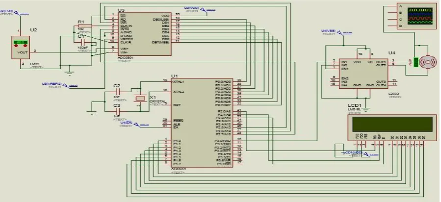
The simulation of the system has been done on Proteus Professional Software v8.0. AT89V51/AT89S52 microcontroller based on Modified Harvard architecture is used in the system. Coding of the system has been done in Embedded ASSEMBLY language. 16X2 LCD display has been used which is connected to PORT 1 of the microcontroller. The simulation of the circuit is shown in Figure 5.
Fig. 5 Simulation circuit
VII. HARDWAREIMPEMENTATION
The Hardware implementation of the system has been done on 8051 Microcontroller Development board. It is widely used till now because it is cheap and can work for the same result as other microcontroller development board can do.
In Figure 6 shown above, connections are provided according to interfacing of all the components such as LM35, ADC0804, AT89S52, L293D, DC fan, LCD. One bulb is there to increase the temperature around temperature sensor LM35. Output has been taken as speed of fan is varying according to temperature shown in LCD.
VIII. RESULTSANDDISCUSSION
The speed of the fan has been controlled using PWM technique according to the room temperature. The simulation of the system has been done on Proteus Professional v 8.0 software packages and it is running in good agreement. The logic used in the system is verified and shown in the flowchart form. The duty cycle has been varied according to room temperature and speed of the fan was controlled accordingly. The graphs showing the relationship between duty cycle and the room temperature are plotted in MATLAB and accuracy of the system was validated. The design of the system presented in this paper is appropriate according to the modern technology.
8.1 Duty Cycle
Duty cycle may be defined as the amount of time in a particular period during which the pulse is active or high. The speed is made slow, medium, fast, very fast and zero by having different duty cycles. Following Figures show the pulses with varying duty cycles for different temperature range as per simulation result.
Duty cycle = ton/ttotal
Where ton is ON time and ttotal is total time duration of pulse generated.
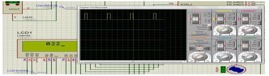
Fig. 7 Pulse for temperature above 20℃ and below 40℃
Figure 7 shows Pulse for temperature above 20℃ and below 40℃. Here variation in pulse is with Duty cycle 25% and at
the same time fan speed is slow and showing 200 rpm. At this time temperature range is greater than 20 and less than 40 degree Celsius.
Figure 8 shows Pulse for temperature above 20℃ and below 40℃. Here the variation of pulse is with Duty cycle 65% and at the same time fan speed is fast and showing 480 rpm. At this time temperature range is greater than 40 and less than 60 degree Celsius.
Fig. 9 Pulse for temperature above 60℃
Figure 9 showsPulse for temperature above 60℃. Here the variation of pulse is with Duty cycle 95% and at the same
time fan speed is very fast and showing 770 rpm. At this time temperature range is greater than 60 degree.
The temperature sensor senses the room temperature and it is displayed on the LCD. The speed of the fan is controlled by using PWM technique according to the room temperature. For processing analog signals, we have analog to digital converters interfaced with microcontroller, which converts analog signals to digital ones. The temperature sensor LM35 interfaced to the analog input port of ADC0804 acquires the room temperature and converts it into digital voltage signal. Figure 10 shows the relationship between digital voltage and the temperature.
Fig. 10 Digital Voltage vs. Temperature (in Fahrenheit)
8.2 Variation in duty cycle and speed according to temperature variation as per Simulation result
Table 1 Results of Duty cycle and Speed with Temperature in software Proteus
Temperature (in ℃)
Duty Cycle Speed
(rpm)
1 Less than 20 0 0 (Zero)
2 20 to 40 25 200 (Slow)
3 40 to 60 50 480 (Fast)
4 Above 60 95 770 (Very fast)
Now According to the readings from the temperature sensor, duty cycle has been varied automatically thus controlling fan speed on hardware. Speed has been measured using “digital Tachometer”. Table 2 shows the duty cycles and corresponding Speed varying with the temperature.
Table 2 Results of Duty cycle and Speed with Temperature taken from hardware
Temperature (in ℃)
Duty Cycle Speed
(rpm)
1 Less than 20 0 0 (Zero)
2 20 to 40 25 187 (Slow)
3 40 to 60 50 474 (Fast)
4 Above 60 95 919 (Very fast)
The slow speed corresponds to 25 percent duty cycle and fast corresponds to 95 percent duty cycle. The variation of the duty cycle with temperature (in Celsius) is shown in the Figure 11. The fan is in full swing when the Duty cycle is made 95 percent.
l
Fig. 11 Temperature (in oC) vs. Duty Cycle
IX.CONCLUSIONS
duty cycle and speed of DC Fan according to temperature variation in software and hardware I have observed approximately same result.
This design can be further extended in terms of area and power at layout and characteristic level by using Advanced VLSI applications.
ACKNOWLEDGEMENT
The authors are thankful to Vaibhav Bhatia and Gavish Bhatia, whose research papers are helpful to develop my research work and also to B.I.T., Sindri, Dhanbad, Jharkhand India for providing support and facilities to carry out this research work.
REFERENCES
[1] R.Krishnan, “Electric Motor Drives Modelling, Analysis, and Control, Prentice Hall International Inc., New Jersey, 2001.
[2] Duane, H., Brushless Permanent Magnet Motor Design. University of Maine, Orno, USA, 2nd edition, 2002.
[3] F. Luo, X. Zhao, and Y. Xu, "A new hybrid elevator group control system scheduling strategy based on particle swarm simulated annealing optimization algorithm", Intelligent Control and Automation (WCICA), pp. 5121-5124, 2010.
[4] Fundamentals of electric drive by Gopal k dubey”, narosa publishing house New Delhi,1989
[5] A. Z. Ahmad and M. N. Taib, A study On the DC Motor Speed Control by Using Back-EMF Voltage, Asia SENSE SENSOR, 359-364, 2003. [6] I. John, PIC Microcontroller Project Book, second ed., Mc Graw-Hill, Singapore, 2000.
[7] Xiaodong Xia, Based on Single Chip Microcomputer Remote Wireless Control System Design. Coal Mine Machinery, vol. 32 (8), pp. 202-204, 2011.
[8] J. Vig and A. Ballato, “Ultrasonic Instruments and Devices”, Academic Press Inc. pp. 637– 701 (Chapter7: Frequency Control Devices). 1999 [9] P. Spasov, “Micro controller Technology, The 68HC1 l”, Prentice Hall, 1992.
[10] M. H. Rashid, Power Electronics Circuits, Devices and Applications, third ed., Prentice Hall, United States of America, 2004.
[11] Song jian, Jiang junsheng, Zhao wenliang. "The DC-motor PWM Speed Regular system Base on single-chip Microcomputer". Study on Agricultural Mechanization, 1(1):102-103, 2006.
[12] J. Holtz, “Pulse width modulation: a survey,” IEEE Trans. Industrial Electronics, vol. IE-39, no.5 pp.410-420, 1992.
[13] S.D. Barman, A. Hussain, T. Ahmed, Speed Control of DC Motor Using PWM Technique: Pulse Width Modulated DC Motor Control, LAP Lambert Academic Publishing, 2012.
[14] T.Pialis and K. Phang, “Analysis of timing Jitter in Ring Oscillators Due to Power Supply Noise”, Circuits and Systems, ISCAS’03,
Proceedings of the 2003 International Symposium. 2003.
[15] Vaibhav Bhatia and Gavish Bhatia “Room Temperature based Fan Speed Control System using Pulse Width Modulation Technique”
International Journal of Computer Applications (0975 – 8887) Volume 81 – No5, November 2013
[16] S.Ravi and P.A.Balakrishnan’s “DESIGN AND DEVELOPMENT OF A MICROCONTROLLER BASED NEURO FUZZY TEMPERATURE CONTROLLER” IEEE/OSA/IAPR International Conference on Infonnatics, Electronics & Vision.