Available Online atwww.ijcsmc.com
International Journal of Computer Science and Mobile Computing
A Monthly Journal of Computer Science and Information Technology
ISSN 2320–088X
IJCSMC, Vol. 3, Issue. 10, October 2014, pg.380 – 386
RESEARCH ARTICLE
F
AULT
C
URRENT
I
NTERRUPTION OF
V
OLTAGE
S
AGS BY
D
YNAMIC
V
OLTAGE
R
ESTORER
Neela Srividya
1M.Tech1
Project Guide & HOD:
Sri. T.V.V. Pavan Kumar
2 M.Tech, Associate Professor2Global Institute of Engineering & Technology12
Abstract: Voltage sag is the most severe type of power quality disturbance faced by many commercial and industrial customers. The proliferation of voltage sag load equipment used in industrial plants may cause tremendous economic and financial losses up to millions of dollars attributed to a single disruption. Therefore, it is very important to mitigate the impact of voltage sags on sensitive equipment. In this paper, Dynamic Voltage Restorer (DVR) is used to mitigate the voltage sag during fault condition. DVR is considered to be the most efficient and effective mitigation device. The method to calculate the DVR devices for the fault calculation, were consider in this paper, as well as the control strategy. The mitigation technique was applied to an IEEE 30-buses electrical network to illustrate its application. The results show that the mitigation technique is able to mitigate voltage sag. Analyses of the voltage sag magnitude had shown the different with and without DVR for the network system. Index Terms— dynamic voltage restorer, voltage sag, power quality, voltage sags, balanced and unbalanced faults
sags, voltage swells and short interruptions are the most common types of voltage abnormalities [3]. Voltage sag accounts for the highest percentage of equipment interruptions, about 31% [4]. Voltage magnitude and duration are essential characteristics of voltage sag. The voltage sag magnitude, which is the remaining voltage during the event, depends not only on the fault type and fault location but also on other factors such as pre-fault voltages, transformer connection and fault impedance. The duration of voltage sag is defined as the time during which the voltage magnitude (RMS voltage) is below a given voltage threshold. In the event of a fault in the network, the ensuing voltage sag will last until protective devices acts to interrupt the flow of fault current. Due to this uncontrollable voltage sag phenomena, sensitive equipment used in industrial plants, such as process controllers, adjustable speed drives, computers, programmable logic controllers, robotics, banks, data centers and customer service centers may cause tremendous economic and financial losses up to millions of dollars attributed to a single disruption [5], [6]. An increasing demand for high quality, reliable electrical power an increasing number of distorting loads have led to an increased awareness of power quality by customer and utilities. Therefore it is very important to mitigate the impact of voltage sags on sensitive equipment. For voltage sag mitigation, power electronic or static controllers in medium and low voltage distribution systems use mitigation devices for the purpose of supplying a nominal voltage [7], [8]. The most commonly used devices to mitigate voltage sag are the DVR and STATCOM as illustrated in [8], [9]. In this paper, a series compensation mitigation device, commonly called dynamic voltage restorer (DVR), has been applied as a definitive solution due to the advantages of the series compensation over the shunt compensation [9], [10]. DVR is commonly used to mitigate voltage sag, voltage swell, voltage harmonic and voltage fluctuations as it is a compensating type mitigation device.
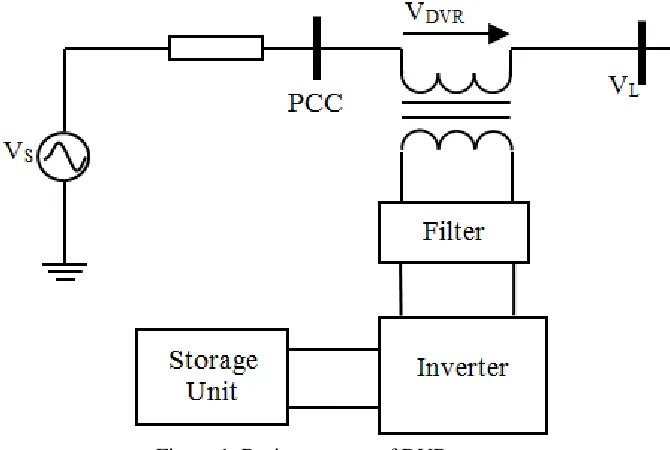
II. DYNAMIC VOLTAGE RESTORER
Figure 1. Basic structure of DVR
A. Energy Storage Unit
During voltage sag condition, energy storage is used to provide the shortage of missing energy. Commercially available DVRs use large capacitor banks. The capacity of the energy storage device has a big impact on the compensation capability of the system. DVRs can be configured alternatively to use line energy supply, that is, they absorb the energy that is to be injected from the utility feeder itself into the distribution circuit.
B. Voltage Source Inverter
The DC voltage is converted from the energy storage unit to a controllable AC voltage which is to be injected to the line voltage.
C. Filter Circuit
Normally, a second-order LC filter is introduced between the inverter and the transformer to cancel high frequency harmonic components in the inverter output voltage.
D. Bypass Switches and Control Circuits
III. CONTROL STRATEGY
Different type of voltage sag and load conditions can limit the possibility of compensating voltage sag. Therefore, the control strategy depends on the type of load characteristics. There are three different methods to inject DVR compensating voltage.
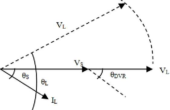
A. Pre-fault Compensation
Pre-fault control strategy restores voltage to the prefault value, i.e. both sag magnitude and phase shift are compensated. The reference voltage is set as pre-fault voltage magnitude and phase angle. Fig. 2 shows the single-phase vector diagram of pre-fault compensation method [10].
Figure 2. Pre-fault compensation method.
B. In-phase Compensation
In-phase voltage compensation method restores voltage to be in phase with the voltage sag. In other words, the phase angle will be same as the angle of sagged voltage while the voltage magnitude is restored to pre-fault value. Fig 3 shows the single-phase vector diagram for in-phase compensation method [10].
Figure 3. In-phase compensation method
performance are important in pre-sag and in-phase compensation methods, due to the limited energy storage of the capacity unit.
C. In-phase Advance Compensation
The advantage of in-phase advance compensation is that less active power needs to be injected from DVR energy storage unit into the distribution system. Fig. 4 shows the single-phase vector diagram of in-phase advance compensation method [10].
Figure 4. In-phase advance compensation method
IV. METHODOLOGY TO DETERMINE DVR INJECTION VOLTAGE
network which can simulate the entire network. In this study the pre-fault compensation method was used. The load voltage can express, when there is sag voltage and the voltage injected by the DVR is given by:
Vl = Vsag + VDVR (1)
where: Vl is the load voltage, Vsag is the sagged supply voltage and VDVR is the voltage injected by DVR.
A. Injection of Reactive Power.
When injected reactive power only from DVR, the power equation given by: jQ = VDVR + Il (2)
Sl = Vl + Il (3)
where: Q is the injected reactive power by DVR, Sl is the load at bus and Il is the load current.
V. RESULTS
VI. CONCLUSION
In this paper, the operation and capability of DVR used in system network is introduced. Detailed components and working principles of DVR were explained. Methods of control strategies for voltage compensation for three different types of control systems were illustrated in detail. Calculations of DVR were derived in order to minimize the input of real power. Based on the calculation, the magnitude of injection of voltage and current (real power and reactive power) by DVR can be obtained. The capability of the simulation with and without DVR, were demonstrated on 30-bus generic distribution system. The efficiency of the mitigation devices can be seen from the results obtained with and without DVR.
REFERENCES
[1] M. H. J. Bollen, “Understanding power quality problems: Voltage sags and interruptions,” ser. Power
Engineering, Piscataway, NJ: IEEE Press 2000.
[3] M. T. Aung, J. V. Milanovic, and C. P. Gupta, “Propagation of assymmetrical sags and the innfluence of boundary crossing lines on voltage sag prediction,” IEEE Trans. Power Del., vol. 19, no. 4, pp. 1819-1827, Oct 2004.
[4] I. Hunter, “Power quality issues: A distribution company perpective,” Power Engineering Journal, vol. 15, pp. 75-80, 2001.
[5] J. V. Milanovic and C. P. Gupta, “Probabilistic of financial losses due to interruptions and voltage sags–Part I: The methodology,” IEEE Trans Power Del., vol. 21, no. 2, pp. 918-924, 2006.
[6] J. V. Milanovic and C. P. Gupta, “Probabilistic of financial losses due to interruptions and voltage sags–Part II: Practical implementation,” IEEE Trans Power Del., vol. 21, no. 2, pp. 925- 932, 2006.
[7] A. Ghosh and Gerard, “Power quality enhancement using custom power devices,” Kluwer Power
Electronics and Power SystemSeries, 2002.
[8] A. Ghosh and G. Ledwich, “Compensation of distribution system using DVR,” IEEE Trans. on Power Del., vol. 17, pp. 1030-1036, 2002.
[9] D. V. Hertem, M. Didden, J. Driesen, and R. Belmans, “Choosing the correct mitigation method against voltage dips and interruption: A customer-based approach,” IEEE Trans. on Power Delivery, vol. 22, no. 1, pp. 331-391, Jan 2007.