Source and Channel Adaptive Rate Control
for Multicast Layered Video Transmission
Based on a Clustering Algorithm
J ´er ˆome Vi ´eron
Thomson multimedia R&D, 1 avenue Bellefontaine - CS 17616, 35576 Cesson-S´evign´e, France Email:[email protected]
Thierry Turletti
INRIA, 2004 route des Lucioles - BP 93, 06902 Sophia Antipolis Cedex, France Email:[email protected]
Kav ´e Salamatian
Laboratoire d’Informatique de Paris 6 (LIP6), 8 rue du Capitaine Scott, 75015 Paris, France Email:[email protected]
Christine Guillemot
INRIA, Campus de Beaulieu, 35042 Rennes Cedex, France Email:[email protected]
Received 24 October 2002; Revised 8 July 2003
This paper introduces source-channel adaptive rate control (SARC), a new congestion control algorithm for layered video trans-mission in large multicast groups. In order to solve the well-known feedback implosion problem in large multicast groups, we first present a mechanism for filtering RTCP receiver reports sent from receivers to the whole session. The proposed filtering mechanism provides a classification of receivers according to a predefined similarity measure. An end-to-end source and FEC rate control based on this distributed feedback aggregation mechanism coupled with a video layered coding system is then described. The number of layers, their rate, and their levels of protection are adapted dynamically to aggregated feedbacks. The algorithms have been validated with the NS2 network simulator.
Keywords and phrases:multicast, congestion control, layered video, aggregation, FGS.
1. INTRODUCTION
Transmission of multimedia flows over multicast channels is confronted with the receivers heterogeneity problem. In a multicast topology (multicast delivery tree in the 1→Ncase, acyclic graph in theM →Ncase), network conditions such as loss rate (LR) and queueing delays are not homogeneous in the general case. Rather, there may be local congestions affecting downstream delivery of the video stream in some branches of the topology. Hence, the different receivers are connected to the source via paths with varying delays, loss, and bandwidth characteristics. Due to this potential hetero-geneity, dynamic adaptation of multimedia flows over multi-cast channels, for optimized quality-of-service (QoS) of
Layered transmission has been proposed to cope with re-ceivers heterogeneity [1,2,3]. In this approach, the source is represented using a base layer (BL) and several successive enhancement layers (EL) refining the quality of the source re-construction. Each layer is transmitted over a separate mul-ticast group, and receivers decide the number of groups to join (or leave) according to the quality of their reception. At the other side, the sender can decide the optimal num-ber of layers and the encoding rate of each layer according to the feedback sent by all receivers. A variety of multicast schemes making use of layered coding for audio and video communication have been proposed, some of which rely on a multicast feedback scheme [3,4]. Despite rate adaptation to the network state, applications have to face the remain-ing packet losses. Error control schemes usremain-ingforward error
correction(FEC) strongly reduce the impact of packet losses
[5,6,7]. In these schemes, redundant information are sent along with the original information so that the lost data (or at least part of it) can be recovered from the redundant in-formation. Clearly, sending redundancy increases the proba-bility of recovering the lost packets, but it also increases the bandwidth requirements, and thus the LR of the multimedia stream. Therefore, it is essential to couple the FEC scheme to the rate control scheme in order to jointly determine the transmission parameters (redundancy level, source coding rate, type of FEC scheme, etc.) as a function of the state of the multicast channel, to achieve the best subjective quality at receivers. For such adaptive mechanisms, it is important to have simple channel models that can be estimated in an online manner.
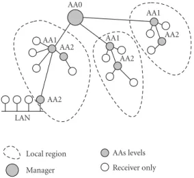
The sender, in order to adapt the transmission param-eters to the network state, does not need reports of each receiver in the multicast group. It rather needs a parti-tion of the receivers into homogeneous classes. Each layer of the source can then be adapted to the characteristics of one class or of a group of classes. Each class represents a group of homogeneous receivers according to discrimina-tive variables related to the received signal quality. The clus-tering mechanism used here follows the above principles. A classification of receiver reports (RRs) is performed by aggregation agents (AAs) organized into a hierarchy of lo-cal regions. The approach assumes the presence of AAs at strategic positions within the network. The AAs classify re-ceivers according to similar reception behaviors and filter correspondingly the (real-time transport control protocol) RTCP RRs. By classifying receivers, this mechanism solves the feedback implosion problem and at the same time pro-vides the sender with a compressed representation of the receivers.
In the experiments reported in this paper, we consider two pairs of discriminative variables in the clustering process: the first one constituted of the LR and thegoodputand the second constituted of the LR and the throughput of a con-formant TCP (transport control protocol) connection under similar loss and round-trip time (RTT) conditions. We show approaches in which receivers rate requests are only based on the goodput measure risk leading to a severe subutilization of
the network resources. To use a TCP throughput model, re-ceivers have to estimate their RTT to the source first. In order to do so, we use the algorithm described in [4] jointly with a new application-defined RTCP packet, calledprobe RTT.
This distributed feedback aggregation mechanism is cou-pled with a video fine-grain scalable (FGS) layered coding system to adapt dynamically the number of layers, the rate of each layer, and its level of protection. Notice that the aggre-gation mechanism that has to be supported by the network nodes remains generic and can be used for any type of me-dia. The optimization is performed by the sender and takes into account both the network aggregated state as well as the rate-distortion characteristics of the source. The latter allows to optimize the quality perceived by each receiver in the mul-ticast tree.
The remainder of this paper is organized as follows. Section 2provides an overview of related research on mul-ticast rate and congestion control. Section 3 sets the main lines of SARC, our new hybrid sender/receiver driven rate control based on a clustering algorithm. The protocol func-tions to be supported by the receivers and the receiver clus-tering mechanism governing the feedback aggregation are described, respectively, in Sections 4 and 5. Section 6 de-scribes the multilayer source and channel rate control and the multi-layered MPEG-4 FGS source encoder [8,9] that have been used in the experiments. Finally, experimental results obtained with the NS2 network simulator with various dis-criminative clustering variables (goodput, TCP-compatible throughput), including the additional usage of FEC are dis-cussed inSection 7.
2. RELATED WORK
Related work in this area focuses on error, rate, and conges-tion control in multicast for multimedia applicaconges-tions. Lay-ered coding is often proposed as a solution for rate con-trol in video multicast applications over the Internet. Several approaches—sender-driven [10], receiver-driven [11,12], or hybrid schemes [3,13,14]—have been proposed to address the problem of rate control in a multicast transmission. Receiver-driven approaches consist in multicasting different layers of video using different multicast addresses and let the receivers decide which multicast group(s) to subscribe to. RLM (receiver-driven layered multicast) [11] and RLC (radio link control) [12] are two well-known receiver-driven lay-ered multicast congestion control protocols. However, they both suffer from pathological behaviors such as transient pe-riods of congestion, instability, and periodic losses. These problems mainly come from the bandwidth inference mech-anism used [15]. For example, RLM uses join experiments
congestion and periodic losses [15]. PLM (Packet-pair lay-ered multicast) [16] is a more recent layered multicast con-gestion control protocol, based on the generation of packet pairs to infer the available bandwidth. PLM does not suffer from the same pathological behaviors as RLM and RLC but requires a fair queuing network.
Bhattacharya et al. [17] present a general framework for the analysis of additive increase multiplicative decrease (AIMD) multicast congestion control protocols. This paper shows that because of the so-called “path loss multiplicity problem,” unclever use of congestion information sent by re-ceivers to 1 sender may lead to severe degradation and lack of fairness. This paper formalizes the multicast congestion control mechanism in two components: the loss indication filter (LIF) and the rate adjustement algorithm. Our paper presents an implementation that minimises the loss multi-plicity problem by using an LIF which is implemented by a clustering mechanism (Section 5.2) and a rate adjustement algorithm following the algorithm described in Sections 4 and6.
TFMCC [18] is an equation-based multicast congestion control mechanism that extends the TCP-friendly TFRC [19] protocol from the unicast to the multicast domain. TFMCC uses a scalable RTT measurement and a feedback suppression mechanism. However, since it is a single-rate congestion con-trol scheme, it cannot handle heterogeneous receivers and adapts its sending rate to the current limiting receiver.
FLID-DL [20] is a multirate congestion control algo-rithm for layered multicast sessions. It mitigates the negative impact of long Internet group management protocol (IGMP) leave latencies and eliminates the need for probe intervals used in RLC. However, the amount of IGMP and PIM-SM (protocol independent multicast-sparse mode) control traf-fic generated by each receiver is prohibitive. WEBRC [21] is a new equation-based rate control algorithm that has been recently proposed. It solves the main drawbacks of FLID-DL using an innovative way to transmit data in waves. However, WEBRC, such as FLID-DL, is intended for reliable download applications and possibly streaming applications but can-not be used to transmit real-time hierarchical flows such as H.263+ or MPEG-4.
A source adaptive multilayered multicast (SAMM) algo-rithm based on feedback packets containing information on the estimated bandwidth (EB) available on the path from the source is described in [3]. Feedback mergers are assumed to be deployed in the network nodes to avoid feedback implo-sion. A mechanism based onpartial suppressionof feedbacks is proposed in [4]. This approach avoids the deployment of aggregation mechanisms in the network nodes, but on the other hand, the partial feedback suppression will likely in-duce a flat distribution of the requested rates.
MLDA [13] is a TCP-compatible congestion control scheme in which, as in the scheme we propose, senders can adjust their transmission rate according to feedback informa-tion generated by receivers. However, MLDA does not pro-vide a way to adapt the FEC rate in the different layers ac-cording to the packet loss observed at receivers. Since the
feedback only includes TCP-compatible rates, MLDA does not need feedback aggregation mechanisms and uses expo-nentially distributed timers and a partial suppression mech-anism to prevent feedback implosion. However, when the re-ceivers are very heterogeneous, the number of requested rates (in the worst case on a continuous scale) can potentially lead to a feedback implosion. Moreover, the partial suppression algorithm does not allow quantifying the number of receivers requesting a given rate in order to estimate how representa-tive this rate is.
In [14], a rate-based congestion and loss control mecha-nism for multicast layered video transmission is described. The strategy relies on a mechanism that aggregates feed-back information in the networks nodes. However, in con-trast with SAMM, the optimization is not performed in the nodes. Source and channel FEC rates in the different layers are chosen among a set of requested rates in order to maxi-mize the overall peak signal-to-noise ratio (PSNR) seen by all the receivers. Receivers are classified according to their avail-able bandwidth, and for each class of rate, two types of infor-mation are delivered to the sender: the number of receivers represented by this class and an average LR computed over all those receivers. It is supposed here that receivers with similar bandwidths have similar LRs, which may not always be the case. In this paper, we solve this problem using a distributed clustering mechanism.
Clustering approaches have been already considered sep-arately in [22,23]. In [22], a centralized classification ap-proach based on k-means clustering is applied on a qual-ity of reception parameter. This qualqual-ity of reception pa-rameter is derived, based on the feedback of receivers con-sisting of reports including the available bandwidth and packet loss. The main difference, compared with our ap-proach, is that in our case, the classification is made in a dis-tributed fashion. Hence, receivers with similar bandwidths but with different LRs are not classified within the same class. Therefore, with more accurate clusters, a better adap-tation of the error control process at the source level is pos-sible. The global optimization performed is different and leads to improved performances. Moreover, [22] uses the RTCP filtering mechanism proposed in the RTP (real-time transport protocol) standard, that is, they adapt the RTCP sending rate according to the number of receivers. How-ever, when the number of receivers is large, it is not pos-sible to get a precise snapshot of quality observed by re-ceivers.
3. PROTOCOL OVERVIEW
This section gives an overview of the SARC protocol pro-posed in this paper. Its design relies on a feedback tree struc-ture, where the receivers are organized into a tree hierarchy, and internal nodes aggregate feedbacks.
received quality would not be acceptable, whereasRmax cor-responds to the rate above, under which there is no signifi-cant improvement of the visual quality. This information is transmitted to the receivers at the start of the session. The in-terval [Rmin,Rmax] is then divided into subintervals in order to only allow relevant values for layers rates. This quantiza-tion avoids having nonquality discriminative layers.
After this initialization, the multicast layered rate control process can start. The latter assumes that the time is divided into feedback rounds. A feedback round comprises four ma-jor steps.
(i) At the beginning of each round, the source announces the number of layers and their respective rates via RTCP sender reports (SRs). Each source layer is trans-mitted to an Internet protocol (IP) multicast group. (ii) Each receiver measures network parameters and
esti-mates the bandwidth available on the path leading to it. The EB and the layer rates will trigger subscriptions or unsubscriptions to/from the layers. EB and LRs are then conveyed to the sender via RTCP RR.
(iii) AAs placed at strategic positions within the network classify receivers according to similar reception behav-iors, that is, according to a measure of distance be-tween the feedback parameter values. On the basis of this clustering, these agents proceed with the aggrega-tion of the feedback parameters, providing a represen-tation of homogeneous clusters.
(iv) The source then proceeds with a dynamic adaptation of the number of layers and of their rates in order to maximize the quality perceived by the different clus-ters.
Sections4,5, and6describe in details each of the four steps.
4. PROTOCOL FUNCTIONS SUPPORTED BY THE RECEIVER
Two bandwidth estimation strategies have been considered: the first approach measures the goodput of the path and the second estimates the TCP-compatible bandwidth under sim-ilar conditions of LRs and delays. This section describes the functions supported by the receiver in order to measure the corresponding parameters and the multicast groups join and leave policy that has been retained. The bandwidth values es-timated by the receivers are then conveyed to the sender via RTCP RRs augmented with dedicated fields.
4.1. Goodput-based estimation
A notion of goodput has been exploited in the SAMM algo-rithm described in [3]. Assuming the priority-based diff eren-tiated services for the different layers, the goodput is defined as the cumulated rate of the layers received without any loss. If a layer has suffered from losses, it will not be considered in the goodput estimation. The drawback of such a measure is that the EB will be highly dependent on the sending rates,
hence it does not allow an accurate estimation of the link ca-pacity. When no loss occurs, in order to best approach the link capacity, SAMM considers values higher than the good-put measured. Nevertheless, a LR of 0% is not realistic on the Internet. Experiments have shown that this notion of good-put in a best-effort network, in presence of cross traffic, leads to EBs decreasing towards zero during the sessions. Here, the goodput is defined instead as the rate received by the end sys-tem. A simple mechanism has been designed to try to ap-proach the bottleneck rate of the link. If the LR is under a given threshold Tloss, the bandwidth valueBt estimated at
timetis incremented as
Bt=Bt−1+∆, (1)
where∆represents a rate increment andBt−1represents the last estimated value. Letgtbe the observed goodput value at
timet. Thus, when the LR becomes higher than the threshold Tloss,Btis set togt.
In the experiments we have takentloss = 3% and the∆ parameter increases similarly to the TCP increase, that is, of one packet per RTT.
4.2. TCP-compatible bandwidth estimation
The second strategy considered for estimating the bandwidth available on the path relies on the analytical model of TCP throughput [24], known also as the TCP-compatible rate control equation. Notice, however, that the application of the model in a multicast environment is not straightforward.
4.2.1. TCP throughput model
The average throughput of a TCP connection under given delay and loss conditions is given by [24]:
T= MSS
RTT2p/3 +Tomin
1, 33p/8p1 + 32p2, (2)
where p, RTT, MSS, andTorepresent, respectively, the
con-gestion event rate [19], the round-trip time, the maximum segment size (i.e., maximum packet size), and the retransmit time out value of the TCP algorithm.
4.2.2. Parameters estimation
the congestion event ratepis done as in [25] and the param-eter MSS is set to 1000 bytes.
4.2.3. Singular receivers
In highly heterogeneous environments, under constraints of bounded numbers of clusters, the rate received by some end systems may strongly differ from their requests, hence from the TCP-compatible throughput value. The resulting exces-sively low values of congestion event rates lead in turn to overestimated bandwidth values, hence to unstability. In or-der to overcome this difficulty, the TCP-compatible through-putBtat timetis estimated as
Bt=min
T, maxSrate+Trate,Bt−1
, (3)
whereSrateis the rate subscribed to,Trateis a threshold cho-sen so that the increase between two requests is limited (i.e., Trate=K×MSS/RTT withKa constant), andBt−1is the last estimated value of the TCP-compatible throughput. When the estimated throughput value T is not reliable, the his-tory used in the estimation of LRs is reinitialized using the method described in [19]. We will see in the experimentation results that the above algorithm is still reactive and respon-sive to changes in network conditions.
4.2.4. Slow-start mechanism
The slow-start mechanism adopted here differs from the ap-proaches described in [18,19]. At the beginning of the ses-sion or when a new receiver joins the multicast transmisses-sion tree, the requested rate is set toRmin. Then, after having a first estimation of RTT and p,T can be computed and the resulting requested rateBtslowis given by
Bslowt =max
T,gt+K×MSS
RTT
, (4)
wheregtis the observed goodput value at timetandKis the
same constant as the one used inSection 4.2.3. The estima-tion given by (4) is used until we observe the first loss. After the first loss, the loss history is reinitialized takinggt as the
available bandwidth and proceeding with (3).
4.3. Join/leave policy
Each receiver estimates its available bandwidthBt and joins
or leaves layers accordingly. However, the leaving mechanism has to take into account the delay between the instant in which a feedback is sent and the instant in which the sender adapts the layer rates accordingly. Undesirable oscillations of subscription may occur if receivers decide to unsubscribe a layer as soon as the TCP-compatible throughput estimated is lower than the current rate subscribed to. It is essential to leave enough time for the source to adapt its sending rates, and only then decide to drop a layer if the request has not been satisfied. That is why in order to be still reactive, we have chosen a delay ofK×RTT before leaving a layer except in the case where the LR becomes higher than a chosen
ac-LAN AA2
AA2
AA2
AA2 AA0
AA1 AA1
AA1
Local region Manager
AAs levels Receiver only
Figure1: Multilevel hierarchy of aggregators.
ceptable boundTloss(Kis the same constant as the one used inSection 4.2.3). These coupled mechanisms permit avoid-ing a waste of bandwidth due to IGMP traffic.
4.4. Signalling protocol
The aggregated feedback information (i.e., EB and LR) are periodically conveyed towards the sender in RTCP RRs, us-ing the RTCP report extension mechanism. The RRs are aug-mented with the following fields:
(i) EB: a 16-bit field which gives the value of the estimated bandwidth expressed in Kbps;
(ii) LR: a 16-bit field which gives the value of the real loss rate;
(iii) NB: a 16-bit field which gives the number of clients requesting this rate (i.e., EB). This value is set to one by the receiver.
5. AGGREGATED FEEDBACK USING DISTRIBUTED CLUSTERING
Multicast transmission has been reported to exhibit strong spatial correlations [26]. A classification algorithm can take advantage of this spatial correlation to cluster similar re-ception behaviors into homogeneous classes. In this way, the amount of feedback required to figure out the state of receivers can be significantly reduced. This will also help in bypassing loss path multiplicity problem explained in [17] by filtering out the receivers’ report of losses. In our scheme, receivers are grouped into a hierarchy of local re-gions (seeFigure 1). Each region contains an aggregator that receives feedback, performs some aggregation statistics, and send them in point-to-point to the higher level aggregator
(merger). The root of the aggregator tree hierarchy (called
themanager) is based at the sender and receives the overall
This architecture has a slight modification compared to the generic RTP architecture. Similar to the PIM-SM context, RRs are not sent in multicast to the whole session, but are sent in point-to-point to a higher level aggregator. As these RTCP feedbacks are local to an aggregator region and will not cross the overall multicast tree, they may be set to be more frequent without breaking the 5% of the overall traf-fic constraint specified by the RTP standard.
5.1. Aggregators organization within the network
AAs must be set up at strategic positions within the net-work in order to minimize the bandwidth overhead of RTCP RRs. Several approaches have been proposed to organize re-ceivers in a multicast session to make scalable reliable multi-cast protocols [27]. We have chosen a multilevel hierarchical approach such as that described in the RMTP [28] protocol in which receivers are also grouped into a hierarchy of local regions. However, in our approach, there are no designated receivers: all receivers send their feedback to their associated aggregator.
The root of the aggregator tree hierarchy (called the man-ager) is based at the sender and receives the overall sum-mary reports. The maximal allowed height of the hierarchi-cal tree is set to 3 as recommended in [29]. In our approach, the overall summary report is a classification containing the number of receivers in each class and the mean behaviour of the class. The mechanism of aggregation is described in Section 5.2.
In our experiments, aggregators are manually set up within the network. However, if extra router functionalities are available, several approaches can be used to automati-cally launch aggregators within the network. For example, we can implement theaggregatorfunction using acustom
con-cast[30].Concastaddresses are the opposite of multicast
ad-dresses, that is, they represent groups of senders instead of groups of receivers. So, a concast datagram contains a multi-cast group source address and a unimulti-cast destination address. With such a scheme, all receivers send their RRs feedback packets using the RTCP source group address to the sender’s unicast address, and only one aggregated packet is delivered to the sender. The custom concast signaling interface allows the application to provide the network with the description of the merging algorithm function.
5.2. Clustering mechanism
The clustering mechanism is aimed towards taking advantage of the spatial and temporal correlation between the receiver’s state of reception. Spatial correlation means that there is re-dundancy between reception behavior of neighbor receivers. This redundancy can be removed by compression methods. This largely reduces the amount of data required for rep-resenting feedback data sent by receivers. The compression is achieved by clustering similar (by a predefined similarity measure) reception behaviors into homogeneous classes. In this case, the clustering can be viewed as a vector quanti-zation [31] that constructs a compact representation of the
receivers as a classification of receivers issuing similar RRs. Moreover, for sender-based multicast regulation, only a clas-sification of receivers is sufficient to apply adaptation deci-sions.
The clustering mechanism can also take advantage of time redundancy. For this purpose, classification of receivers should integrate the recent history of receivers as well as the actual RRs. Different reception states experienced by re-ceivers during past periods are treated as reports of different and heterogeneous receivers. By this way, temporal variation of the quality of a receiver reception are integrated in the clas-sification. A receiver that observes temporal variation may change its class during time.
In a stationary context, the classification would converge to a stable distribution. This stationary distribution will be a function of the spatial as well as the temporal dependen-cies. However, since over large time scales, the stationary hy-pothesis cannot be always validated, a procedure should be added to track variation of the multicast channel and adapt the classification to it. This procedure can follow a classical exponential weighting that drive the clustering mechanism to forget about far past-time reports. In this weighting mech-anism, the weight of clusters is multiplied by a factor (γ <1) at the end of each reporting round, and clusters with weight below a threshold are removed.
Before describing the classification algorithm, several concepts should be introduced. First, we should choose the discriminative characteristic and the similarity (or dissimi-larity) measure needed to detect similar reception behavior.
5.2.1. Discriminative network characteristics
In the system presented in this paper, we have considered two pairs of discriminative variables: the first one constituted of the LR and the goodput (cf.Section 4.1) and the second con-stituted of the LR and a TCP-compatible bandwidth share measure (cf.Section 4.2). Both LR and bandwidth character-istics (goodput or TCP-compatible) are clearly relevant not only as network characteristics but also as video quality pa-rameters.
5.2.2. Similarity measure
Two kinds of measures should be defined: the similarity mea-sure between two observed reports x and y (d(x,y)) and between an observed report x and a cluster C (d(x,C)). The former similarity measure can stand for the simple Lp distance (d(x,y) = p
i(xi−yi)p) or any other more
sophisticated distance suitable to a particular application. The retained similarity measure used in this work is given by d(x,y) = maxi(abs(xi−yi)/dti), wheredti is a chosen
threshold for the dimension i. The latter similarity mea-sure is more difficult to apprehend. The simplest way is to choose in each cluster a representative ˆxC and to
as-sign the distanced(x, ˆxC) to the distance between the point
and the cluster (d(x,C) = d(x, ˆxC)). We can also define
d(x,C)=maxy∈Cd(x,y)). The distance can also be a
like-lihood derived over a model mixture approach. The type of measure used will impact over the shape of the cluster and over the classification.
5.2.3. Classification algorithm
Each cluster is represented by a representative point and a weight. The representative point can be seen as a vector, the components of which are given by the discriminative vari-ables considered in the clustering process.
The clustering algorithm is initialized with a maximal number of classes (Nmax) and a cluster creation threshold (dth). AAs regularly receive RTCP reports from receivers
and/or other AAs in their coverage area as described in Section 5.1. To classify the RRs in the different clusters, we use a very simple nearest neighbor (NN) k-means cluster-ing algorithm (see pseudocode shown inAlgorithm 1). Even if this algorithm might be subject to largely reported de-ficiencies as false clustering, dependencies on the order of presentation of samples, and nonoptimality which has lead researchers to develop more complex clustering mechanism as mixture modelling, we believe that this rather simple al-gorithm attain the goal of our approach which is to filter out RRs to a compact classification in a distributed, asyn-chronous way. A new report joins the cluster that has the lowest Euclidean (L2) distance to it and updates the clus-ter representative by a weighted average of the points in the cluster. When a new point joins a cluster, it changes slightly the representative point which is defined as the cluster center and updates the weight of the cluster; afterwards, the point is dropped to achieve compression. If this minimal distance is more than a predefined threshold, a new cluster is created. This bounds the size of the cluster. We also use a maximal number of clusters (or classes) which is fixed to 5, as it is not realistic to have more layers in such a layered multicast scheme.
At the end of each reporting round, the resulting clas-sification is sent back to the higher level AA (i.e., the man-ager) in the form of a vector of clusters representatives and of their associated weights, and clusters are reset to a null weight. Clusters received by different lower level AAs are clas-sified following a similar clustering algorithm which will ag-gregate representative points of clusters, that is, cluster cen-ter, with the given weight. This amounts to applying the NN clustering algorithm to the representative points reported in the new coming RR.
At the higher level of the aggregators hierarchy, the clus-tering generated by aggregating lower level aggregator re-ports is renewed at the beginning of each reporting round.
As explained before, the classification of receivers should also integrate the recent history of receivers. This memory is introduced into the clustering process by using the cluster obtained during the past reporting round as an a priori in the highest level of the aggregator hierarchy.
Nevertheless, since, over large time scales, the stationary hypothesis cannot be always validated, a procedure must be added to ensure that we forget about far past-time reports
Search for the nearest clusterd(r, ˆC)=minCd(r,C)
if (d(r, ˆC)≥dth)
if(Number of existing cluster< Nmax)
Add a new clusterCnewand set ˆC=Cnew
Recalculate the representative of cluster ˆC,
ˆ xCˆ=
weight( ˆC) ˆxCˆ+r
weight( ˆC) + 1
Increment the weight of cluster ˆC
dth=predefined threshold
Nmax=maximal number of clusters (5)
r=received receiver report
Algorithm1: NN clustering algorithm.
At the beginning of each reporting round
forall clustersC
%Weight the current normalized cluster byγ
weight(C)=weight(C)∗γ
ifweight(C)< wmin
Remove clusterC
Aggregate new normalized reports Send aggregate reports to the sender
wmin=predefined cluster suppression threshold
γ=memory weight
Algorithm 2: Aggregation algorithm at the highest level with memory weighting.
and not to bias the cluster representative by out-of-date re-ports. This is handled by an exponential weighting heuristic: at each reporting round, the weight of a cluster is reduced by a constant factor (seeAlgorithm 2). If the weight of a cluster falls below a cluster suppression threshold level, the cluster is removed.
5.2.4. Cluster management
represented by a weighted average of the two cluster repre-sentatives and a weight corresponding to the sum of the two clusters.
The combination of these three mechanisms of cluster management creates a very dynamic and reactive represen-tation of the reception behaviour observed during the multi-cast session.
6. LAYERED SOURCE CODING RATE CONTROL
The feedback channel created by the clustering mechanism offers periodically to the sender information about the net-work state. More precisely, this mechanism delivers a LR, a bandwidth limit, and the number of receivers within a given cluster. This information is in turn exploited to optimize the number of source layers, the coding mode, the rate, and the level of protection of each layer. This section first describes the media and FEC rate control algorithm that takes into ac-count both the network state and the source rate-distortion characteristics. The FGS video source encoding system used and the structure of the streaming server considered are then described.
6.1. Media and FEC rate-distortion optimization We consider, in addition, the usage of FEC. In the context of transmission on the Internet, error detection is generally provided by the lower layer protocols. Therefore, the upper layers have to deal mainly with erasures or missing packets. The exact position of missing data being known, a good cor-rection capacity can be obtained by systematic maximal dis-tances separable (MDS) codes [32]. An (n,k) MDS code takes kdata packets and producesn−k redundant data packets. The MDS property allows to recover up ton−klosses in a group ofnpackets. The effective loss probabilityPeff(k) of an MDS code, after channel decoding, is given by
Peff(k)=Pe
wherePeis the average loss probability on the channel. One
question to be solved is then, given the effective loss probabil-ity, how to split in an optimal way the available bandwidth for each layer between raw and redundant data. This amounts to finding the level of protection (or the code parameterk/n) for each layer.
The rates for both raw data and FEC (or equivalently, the parameterk/n) are optimized jointly as follows. For a maxi-mum number of layersLsupported by the source, the num-ber of layers, their rate, and their level of protection are cho-sen in order to maximize the overall PSNR seen by all the receivers. Note that the rates are chosen in the set ofN re-quested rates (feedback information). This can be expressed as
mulated source and channel rate andκi/nthe level of
protec-tion for each layeri. The quality measureGto be maximized is defined as
The terms Rj andCj represent, respectively, the requested
rate and the number of receivers in the cluster j. The term PSNR(Ωi) denotes the PSNR increase associated with the
re-ception of the layeri. Note that the PSNR corresponding to a given layeridepends on the lower layers. The termPj,i
de-notes the probability, for receivers of clusterj, that theilayers are correctly decoded and can be expressed as
Pj,i=
the receivers of the clusterjreceiving thekconsidered layers. The values PSNR(Ωi) are obtained by estimating the
rate-distortion D(R) performances of the source encoder on a training set of sequences. The model can then be refined on a given sequence during the encoding process, if the coding is performed in real time, or stored on the server in the case of streaming applications.
The upper complexity bound, in the case of an exhaus-tive search, is given by L!/N!(N−L)!, whereLis the maxi-mum number of layers andNthe number of clusters. How-ever, this complexity can be significantly reduced by first sorting the ratesRjrequested by the different clusters. Once
the ratesRjhave been sorted, the constraint given by (8)
al-lows to limit the search space of the possible combinations of rateriper layer. Hence, the complexity of an exhaustive
search within the resulting set of possible values remains tractable. For large values ofLandN, the complexity can be further reduced by using dynamic programming algorithm [33].
Notice that here we have not considered the use of hier-archical FEC. The FEC used here (i.e., MDS codes) are ap-plied on each layered separately. Only their rateski/nare
op-timized jointly. The algorithm could be extended by using layered FEC as described in [34].
6.2. Fine-grain scalable source
Prediction-based video BL Fine-granular scalable EL
I B P B P
Figure2: FGS video coding scalable structure.
Indeed, even if classical scalable (i.e., SNR, spatial, and tem-poral) coding schemes provide elements of response to the problem of rate adaptation to network bandwidth, those approaches suffer from limitations in terms of adaptation granularity. The structure of the FGS method is depicted in Figure 2. The BL is encoded at a rate denoted byRBL, using a hybrid approach based on a motion compensated temporal prediction followed by a DCT-based compression scheme. The EL is encoded in a progressive manner up to a maximum bit rate denoted byREL. The resulting bitstream is progres-sive and can be truncated at any points, at the time of trans-mission, in order to meet varying bandwidth requirements. The truncation is governed by the rate-distortion optimiza-tion described above, considering the rate-distoroptimiza-tion charac-teristics of the source. The encoder compresses the content using any desired range of bandwidths [Rmin =RBL,Rmax]. Therefore, the same compressed streams can be used for both unicast and multicast applications.
6.3. Multicast FGS streaming server
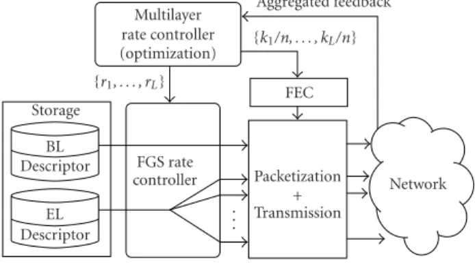
The experiments reported in this paper are done assuming an FGS streaming server.Figure 3shows the internal structure of the multicast streaming system considered including the layered rate controller and the FEC module. For each video sequence prestored on the server, we have two separate bit-streams (i.e., one for BL and one for EL) coupled with its re-spective descriptors. These descriptors contain various infor-mation about the structure of the streams. Hence, it contains the offset (in bytes) of the beginning of each frame within the bitstream of a given layer. The descriptor of the BL contains also the offset of the beginning of a slice (or video packet) of an image. The composition timestamp (CTS) of each frame used as the presentation time at the decoder side is also con-tained in the descriptor.
Upon receiving a new list (r0,r1,. . .,rL) of rate
con-straints, the FGS rate controller computes a new bit budget per frame (for each expected layer) taking into account the frame rate of the video source. Then, at the time of trans-mission, the FGS rate controller partitions the FGS enhance-ment into a corresponding number of “sublayers.” Each layer is then sent to a different IP multicast group. Notice that, re-gardless of the number of FGS ELs that the client subscribes
Descriptor EL Descriptor
BL Storage
FGS rate controller
. . .
Packetization + Transmission
Network
{r1, . . . , rL} FEC
{k1/n, . . . , kL/n}
Multilayer rate controller (optimization)
Aggregated feedback
Figure3: Multicast FGS streaming server.
to, the decoder has to decode only one EL (i.e., the sublayers of the EL merge at the decoder side).
6.4. Rate control signalling
In addition to the value of the RTT computed for the probe RTT packets, the RTCP SRs periodically sent include infor-mation about the sent layers, that is, their number, their rate, and their level of protection, according to the following syn-tax:
(i) NL: an 8-bit field which gives the number of enhance-ment layers;
(ii) BL: a 16-bit field which gives the rate of the base layer; (iii) ELi: a set of 16-bit fields which give the rate of the
en-hancement layeri,i∈1,. . .,NL;
(iv) ki: a set of 8-bit fields conveying the rate of the
Reed-Solomon code used for the protection of layeri,i ∈
0,. . .,NL.1
7. EXPERIMENTAL RESULTS
The performance of the SARC algorithm has been evaluated considering various sets of discriminative clustering variables using the NS2 (version 2.1b6), network simulator.
7.1. Analysis of fairness
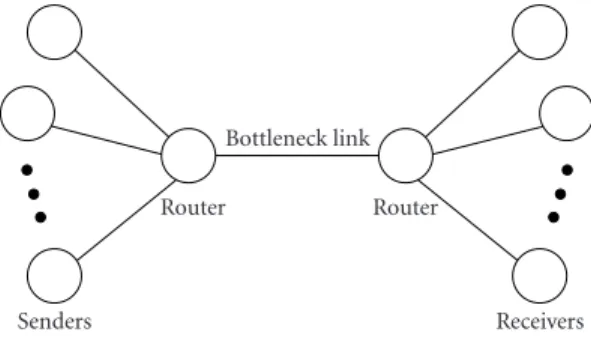
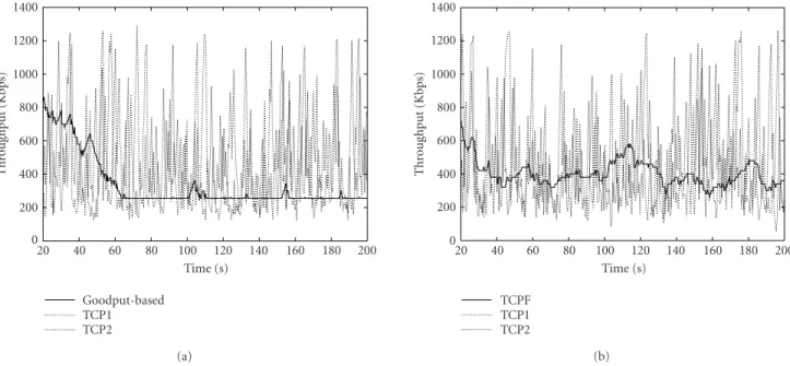
The first set of experiments aimed at analyzing the fairness of the flows produced against conformant TCP flows. Fair-ness has been analyzed using the single bottleneck topology shown in Figure 4. In this topology, a number of sending nodes are connected to many receiving nodes via a com-mon link with a bottleneck rate of 8 Mbps and a delay of 50 milliseconds. The video flows controlled by the SARC protocol are competing with 15 conformant TCP flows. Figure 5a depicts the respective throughput of one video
1Here we consider Reed-Solomon codes of ratesk/n. The value ofnis
Senders Receivers Router
Bottleneck link Router
Figure4: Simulation topology (bottleneck).
flow controlled with the goodput measure and of two out of the 15 TCP flows.Figure 5bdepicts the throughputs ob-tained when using the TCP-compatible rate equation. As ex-pected, the flow regulated with the goodput measure does not compete fairly with the TCP flows (cf. Figure 5a). In the presence of cross traffic at high rate, the EB decreases regularly to reach the lower bound Rmin that has been set to 256 Kbps. The average throughput of the flow regulated with the TCP-compatible measure matches closely the aver-age TCP throughput with a smoother rate (cf.Figure 5b).
7.2. Loss rate and PSNR performances
The second set of experiments aimed at measuring the PSNR and LR performances of the rate control mechanism, with two measures (goodput and TCP-compatible measures), with and without the presence of FEC. We have considered the multicast topology shown in Figure 6. The periodicity of the feedback rounds is set to be equal to the maximum RTT value of the set of receivers. The sequence used in the experiments, called “Brest,”2has a duration of 300 seconds (25 Hz, 6700 frames). The rate-distortion characteristics of the FGS source is depicted inFigure 7. The experiments de-picted here are realized with the MoMuSys MPEG-4 version 2 video codec [9].
7.2.1. Testing scenario
Given the topology of the multicast tree, we have consid-ered a source representation on three layers, each layer be-ing transmitted to an IP multicast address. The BL is en-coded at a constant bit rate of 256 Kbps. The overall rate (base layer plus two ELs) ranges from 256 Kbps up to 1 Mbps. Att = 0, each client subscribes to the three layers with re-spective initial rates ofRBL = 256 Kbps,REL1 = 100 Kbps, and REL2 = 0 Kbps. During the session, the video stream has to compete with point-to-point UDP cross traffic with a constant bit rate of 192 Kbps and with TCP flow. These competing flows contribute to a decrease of the links bot-tleneck. The activation of the cross traffic between clients represented by “squares” on Figure 6, in the time interval from 100 to 200 seconds, limits the bottleneck of the cor-responding link (i.e., LAN 1’s client) down to 320 Kbps.
Sim-2Courtesy of Thomson Multimedia R&D France.
ilarly, competing TCP traffic is generated between clients de-noted by “triangles” in the interval from 140 to 240 sec-onds leading to a bottleneck rate of the link (i.e., LAN 4’s clients) down to 192 Kbps during the corresponding time in-terval.
The first test aimed at showing the benefits for the quality perceived by the receivers of an overall measure that would also take into account the source characteristics (and in par-ticular the rate-distortion characteristics) versus a simple op-timization of the overall goodput. Thus, we compare our re-sults with the SAMM algorithm proposed in [3]. The corre-sponding mechanism is called SAMM-like in the sequel.
The SARC algorithm, relying on the rate-distortion op-timization, has then been tested with, respectively, the good-put and the TCP-compatible measures in order to evidence the benefits of the TCP-compatible rate control in this lay-ered multicast transmission system. In the sequel, these ap-proaches are, respectively, called goodput-based source tive rate control (GB-SARC) and TCP-friendly source adap-tive rate control (TCPF-SARC). The constant K is set to 4 in the experiments. In addition, in order to evaluate the im-pact of the FEC, we have considered the TCP-compatible bandwidth estimation both with and without FEC (TCPF-SARC+FEC) for protecting the BL. When FEC is not applied, thekiparameter of each layer is set ton(i.e., 10 in the
exper-iments).
7.2.2. Results
Figures8and9show the results obtained with the SAMM-like algorithm. It can be seen that the SAMM-SAMM-like ap-proach does not permit an efficient usage of the band-width. For example, the LAN 2’s client (with a link with a bottleneck rate of 768 Kbps) has not received more than 300 Kbps on its link. Similar observations can be done with receivers of other LANs. Notice also that if the rate had not been lower bounded by anRmin value, the goodput of the different receivers would have converged to a very small value. In addition to the highly suboptimal usage of band-width, the approach suffers from a very unstable behavior in terms of subscriptions and unsubscriptions to multicast groups.
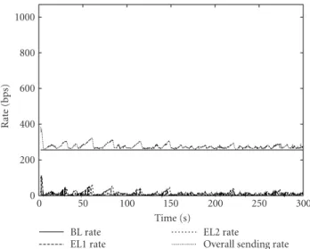
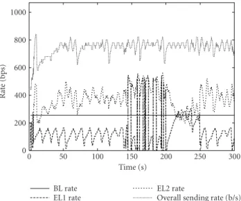
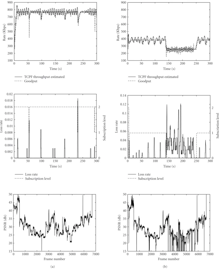
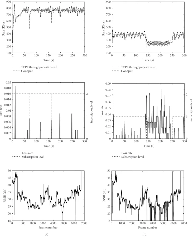
Figures10,11, and12show the rate variations of the dif-ferent layers of the FGS source over the session, obtained, respectively, with the GB-SARC, SARC, and TCPF-SARC+FEC methods. Figures 13, 14, and 15 depict the throughput estimated with these three methods versus the real measures of goodput, the LR, the number of layers re-ceived, and the PSNR values observed for two representative clients (i.e., LAN 2 with a bottleneck rate of 768 Kbps and LAN 4 with a bottleneck rate of 384 Kbps).
Time (s)
20 40 60 80 100 120 140 160 180 200
Thr
o
ug
hpu
t
(Kbps)
0 200 400 600 800 1000 1200 1400
Goodput-based TCP1 TCP2
(a)
Time (s)
20 40 60 80 100 120 140 160 180 200
Thr
o
ug
hpu
t
(Kbps)
0 200 400 600 800 1000 1200 1400
TCPF TCP1 TCP2
(b)
Figure 5: Respective throughputs of two TCP flows and of one rate-controlled flow with (a) a measure of goodput and (b) the TCP-compatible measure.
LAN3 LAN2
LAN1 LAN4
256 Kbps 768 Kbps 384 Kbps 512 Kbps
10 Mbps AA0
AA1
AA2 AA3
AA4
Source
Aggregator Client
TCP cross traffic Cross traffic (192 Kbps)
Figure6: Simulated topology.
groups is strongly reduced. However, the LRs observed re-main high. For example, the LAN 4’s client observe an av-erage LR of 30% between 240 seconds and 300 seconds. This is due to the fact that during this time interval, the receiver of LAN 1 (bottleneck rate of 512 Kbps) has sub-scribed to the first enhancement layer (EL1), hence the rate
Rate (Kbps)
100 200 300 400 500 600 700 800 900 1000 1100
PSNR
(dB)
28 29 30 31 32 33 34
MPEG-4 FGS (with a BL coded at 256 kbps) MPEG-4 version 1
Figure7: Rate-distortion model of the FGS video source.
Time (s)
0 50 100 150 200 250 300
Rat
e
(bps)
0 200 400 600 800 1000
BL rate EL1 rate
EL2 rate
Overall sending rate
Figure8: Rate variations for each layer of the FGS video source with the SAMM-like approach.
Time (s)
0 50 100 150 200 250 300
Rat
e
(Kbps)
100 200 300 400 500 600 700 800 900
SAMM Goodput
Time (s)
0 50 100 150 200 250 300
Rat
e
(Kbps)
100 200 300 400 500 600 700 800 900
SAMM Goodput
Time (s)
0 50 100 150 200 250 300
Loss
ra
te
−1
−0.5 0 0.5 1
Su
b
sc
ri
p
ti
o
n
le
ve
l
0 1 2
Loss rate Subscription level
(a)
Time (s)
0 50 100 150 200 250 300
Loss
ra
te
0 0.02 0.04 0.06 0.08 0.1 0.12 0.14 0.16 0.18 0.2
Su
b
sc
ri
p
ti
o
n
le
ve
l
0 1 2
Loss rate Subscription level
(b)
Time (s)
0 50 100 150 200 250 300
Rat
e
(bps)
0 200 400 600 800 1000
BL rate EL1 rate
EL2 rate
Overall sending rate
Figure10: Rate variations for each layer of the FGS video source with the GB-SARC approach.
Time (s)
0 50 100 150 200 250 300
Rat
e
(bps)
0 200 400 600 800 1000
BL rate EL1 rate
EL2 rate
Overall sending rate (b/s)
Figure11: Rate variations for each layer of the FGS video source with the TCPF-SARC approach.
With the TCPF-SARC algorithm (cf. Figures 11 and 14), the sending rates of the different layers follows closely the variations of the bottleneck rates of the different links. This leads to stable sessions with low LRs and with a re-stricted number of irrelevant subscriptions and unsubscrip-tions to multicast groups. The comparison of the PSNR curves in Figure 14reveals a gain of at least db for LAN 2 with respect to LAN 4. This evidences the interest of such multilayered rate control algorithm in a multicast hetero-geneous environment. Notice that the peaks of
instanta-Time (s)
0 50 100 150 200 250 300
Rat
e
(bps)
0 200 400 600 800 1000
BL rate EL1 rate
EL2 rate
Overall sending rate (b/s)
Figure12: Rate variations for each layer of the FGS video source with the TCPF-SARC + FEC approach.
neous LRs observed result from a TCP-compatible predic-tion which occasionally exceeds the bottleneck rate. Also, inFigure 14b, the LR observed over the time interval from 140 to 240 seconds remains constant and relatively high. This comes from the fact that, in the presence of compet-ing traffic, the bottleneck rate available for the video source is lower than the rate of the BL which in the particular case of an FGS source is maintained constant in average (e.g., 256 Kbps).
The FEC permits improving slightly the PSNR perfor-mances, especially for the receivers of LAN4 (cf.Figure 15b). It can be seen onFigure 12that the usage of FEC however leads to a bit more unstable behavior, that is, to higher rate fluctuations of the different layers of the FGS source.
8. CONCLUSION
Time (s)
0 1000 2000 3000 4000 5000 6000 7000
PSNR
0 1000 2000 3000 4000 5000 6000 7000
PSNR
Time (s)
0 1000 2000 3000 4000 5000 6000 7000
PSNR
0 1000 2000 3000 4000 5000 6000 7000
PSNR
Time (s)
0 1000 2000 3000 4000 5000 6000 7000
PSNR
0 1000 2000 3000 4000 5000 6000 7000
PSNR
REFERENCES
[1] S. McCanne, V. Jacobson, and M. Vetterli, “Receiver-driven
layered multicast,” inProc. Conference of the Special Interest
Group on Data Communication (ACM SIGCOMM ’96), pp. 117–130, Stanford, Calif, USA, August 1996.
[2] T. Turletti, S. Fosse-Parisis, and J. C. Bolot, “Experiments with a layered transmission scheme over the internet,” Tech. Rep. RR-3296, INRIA, Sophia-Antipolis, 1997.
[3] B. J. Vickers, C. Albuquerque, and T. Suda, “Source adaptive multi-layered multicast algorithms for real-time video
distri-bution,”IEEE/ACM Transactions on Networking, vol. 8, no. 6,
pp. 720–733, 2000.
[4] D. Sisalem and A. Wolisz, “MLDA: A TCP-friendly conges-tion control framework for heterogeneous multicast environ-ments,” Tech. Rep., GMD FOKUS, Berlin, Germany, 2000. [5] Y. Wang and Q. F. Zhu, “Error control and concealment for
video communication: A review,”Proceedings of the IEEE, vol.
86, no. 5, pp. 974–997, 1998.
[6] J. C. Bolot, S. Fosse-Parisis, and D. Towsley, “Adaptive
FEC-based error control for internet telephony,” inProc. Conference
on Computer Communications (IEEE Infocom ’99), pp. 1453– 1460, NY, USA, March 1999.
[7] K. Salamatian, “Joint source-channel coding applied to
mul-timedia transmission over lossy packet network,” in Proc.
Packet Video Workshop (PV ’99), NY, USA, April 1999. [8] H. Radha and Y. Chen, “Fine granular scalable video for
packet networks,” inProc. Packet Video Workshop (PV ’99),
Columbia University, NY, USA, April 1999.
[9] Mobile Multimedia Systems (MoMuSys) Software, “MPEG-4 video verification model 4.1”, December 2000.
[10] J. C. Bolot, T. Turletti, and I. Wakeman, “Scalable feedback control for multicast video distribution in the internet,” in
Proc. Conference of the Special Interest Group on Data Com-munication (ACM SIGCOMM ’94), pp. 58–67, London, UK, September 1994.
[11] S. McCanne, M. Vetterli, and V. Jacobson, “Low-complexity
video coding for receiver-driven layered multicast,”IEEE
Jour-nal on Selected Areas in Communications, vol. 15, no. 6, pp. 982–1001, 1997.
[12] L. Vicisano, L. Rizzo, and J. Crowcroft, “TCP-like congestion
control for layered multicast data transfer,” inProc. Conference
on Computer Communications (IEEE Infocom ’98), pp. 996– 1003, San Francisco, Calif, USA, March 1998.
[13] D. Sisalem and A. Wolisz, “MLDA: A TCP-friendly conges-tion control framework for heterogeneous multicast
environ-ments,” inProc. International Workshop on Quality of Service
(IWQoS ’00), Pittsburgh, Pa, USA, June 2000.
[14] X. H´enocq, F. Le L´eannec, and C. Guillemot, “Joint source and channel rate control in multicast layered video
transmis-sion,” inProc. SPIE International Conference on Visual
Com-munication and Image Processing (VCIP ’00), pp. 296–307, Perth, Australia, June 2000.
[15] A. Legout and E. W. Biersack, “Pathological behaviors for
RLM and RLC,” inProceedings of International Conference on
Network and Operating System Support for Digital Audio and Video (NOSSDAV ’00), pp. 164–172, Chapel Hill, NC, USA, June 2000.
[16] A. Legout and E. W. Biersack, “PLM: Fast convergence for
cumulative layered multicast transmission schemes,” inProc.
ACM (SIGMETRICS ’00), pp. 13–22, Santa Clara, Calif, USA, 2000.
[17] S. Bhattacharya, D. Towsley, and J. Kurose, “The loss path
multiplicity problem in multicast congestion control,” inProc.
Conference on Computer Communications (IEEE Infocom ’99), vol. 2, pp. 856–863, NY, USA, March 1999.
[18] J. Widmer and M. Handley, “Extending equation-based
con-gestion control to multicast applications,” inProc. Conference
of the Special Interest Group on Data Communication (ACM SIGCOMM ’01), pp. 275–286, San Diego, Calif, USA, August 2001.
[19] S. Floyd, M. Handley, J. Padhye, and J. Widmer,
“Equation-based congestion control for unicast applications,” inProc.
Conference of the Special Interest Group on Data Communica-tion (ACM SIGCOMM ’00), pp. 43–56, Stockholm, Sweden, August 2000.
[20] J. Byers, M. Frumin, G. Horn, M. Luby, M. Mitzenmacher, A. Roetter, and W. Shave, “FLID-DL: Congestion control for
layered multicast,” inProc. Second International Workshop on
Networked Group Communication (NGC ’00), pp. 71–81, Palo Alto, Calif, USA, November 2000.
[21] M. Luby and V. k. Goyal, “Wave and equation based rate con-trol building block,” Internet Engineering Task Force, Internet Draft draft-ietf-rmt-bb-webrc-04, June 2002.
[22] Q. Guo, Q. Zhang, W. Zhu, and Y.-Q. Zhang, “A sender-adaptive and receiver-driven layered multicast scheme for
video over internet,” inProc. IEEE Int. Symp. Circuits and
Sys-tems (ISCAS ’01), Sydney, Australia, May 2001.
[23] K. Salamatian and T. Turletti, “Classification of receivers in
large multicast groups using distributed clustering,” inProc.
Packet Video Workshop (PV ’01), Taejon, Korea, May 2001. [24] J. Padhye, V. Firoiu, D. Towsley, and J. Kurose, “Modeling
TCP thoughput: a simple model and its empirical validation,” inProc. Conference of the Special Interest Group on Data Com-munication (ACM SIGCOMM ’98), pp. 303–314, University of British Columbia, Vancouver, Canada, August 1998. [25] J. Vi´eron and C. Guillemot, “Real-time constrained
TCP-compatible rate control for video over the internet,” to appear in IEEE Transactions on Multimedia.
[26] M. Yajnik, J. Kurose, and D. Towsley, “Packet loss correlation
in the MBone multicast network,” inProc. IEEE Global
Inter-net Conference, London, UK, November 1996.
[27] B. N. Levine, S. Paul, and J. J. Garcia-Luna-Aceves,
“Or-ganizing multicast receivers deterministically by packet-loss
correlation,” inProc. 6th ACM International Conference on
Multimedia (ACM Multimedia 98), Bristol, UK, September 1998.
[28] S. Paul, K. K. Sabnani, J. C. Lin, and S. Bhattacharya,
“Reli-able multicast transport protocol (RMTP),”IEEE Journal On
Selected Areas in Communications, vol. 15, no. 3, pp. 407–421, 1997.
[29] R. El-Marakby and D. Hutchison, “Scalability improvement of the real-time control protocol (RTCP) leading to
manage-ment facilities in the internet,” inProc. 3rd IEEE Symposium
on Computers and Communications (ISCC ’98), pp. 125–129, Athens, Greece, June 1998.
[30] K. L. Calvert, J. Griffioen, B. Mullins, A. Sehgal, and S. Wen, “Concast: Design and implementation of an active network
service,” IEEE Journal on Selected Area in Communications
(JSAC), vol. 19, no. 3, pp. 720–733, 2001.
[31] Y. Linde, A. Buzo, and R. M. Gray, “An algorithm for vector
quantiser design,”IEEE Transactions on Communications, vol.
28, pp. 84–95, January 1980.
[32] F. J. Mac Williams and N. J. A. Sloane, The Theory of Error
Correcting Codes, North Holland, Amsterdam, 1977.
[33] D. Koo,Elements of Optimization, Springer-Verlag, NY, USA,
1977.
[34] D. Tan and A. Zakhor, “Video multicast using layered FEC
and scalable compression,” IEEE Transactions on Circuits and
J´erˆome Vi´eronreceived his M.S. degree in computer science from the University of Rennes, France, in 1999. From 1999 to 2003, he was pursuing his Ph.D. works at IN-RIA. He received his Ph.D. degree in com-puter science from the University of Rennes, France, in 2003. Currently he is with the Corporate Research Center of Thomson Multimedia R&D in Rennes, France. He works in the Multimedia Streaming &
Stor-age Lab. His research interests are new generation scalable video compression for TV, HDTV, and digital cinema.
Thierry Turletti received his M.S. and Ph.D. degrees in computer science, both from the University of Nice Sophia-Antipolis, France, in 1990 and 1995, respectively. He has done his Ph.D. studies in the RODEO group at INRIA Sophia Antipolis. During 1995–1996, he was a Postdoctoral Fellow in the Telemedia, Networks and Systems Group at the MIT Laboratory for Computer Science (LCS),
Massachusetts Institute of Technology (MIT). He is currently a Research Scientist at the Plan`ete group at INRIA Sophia Antipolis. His research interests include multimedia applications, congestion control, and wireless networking. Dr. Turletti currently serves on the editorial board of Wireless Communications and Mobile Computing.
Kav´e Salamatianis an Associate Professor at Paris VI University in France and con-ducts his researches at LIP6. His main areas of research are networking information the-ory and Internet measurement and mod-elling. He is actually the coordinator of a large research effort in Internet measure-ment and modelling in France. He has grad-uated in 1998 from Paris-SUD Orsay Uni-versity with a Ph.D. degree in computer
sci-ence. He worked during his Ph.D. on joint source-channel coding applied to multimedia transmission over Internet. Dr. Salamatian also has an M.S. in theoretical computer science from Paris XI Uni-versity (1996) and an M.S. in communication engineering from Is-fahan University of Technology (1995).
Christine Guillemotis currently “Directeur de Recherche” at INRIA, in charge of a research group dealing with image mod-elling, processing, and video communica-tion. She holds a Ph.D. degree from Ecole Nationale Sup´erieure des Telecommunica-tions (ENST), Paris. From 1985 to October 1997, she has been with CNET France Tele-com where she has been involved in vari-ous projects in the domain of coding for TV,