Image De-noising using Contoulets
(A Comparative Study with Wavelets)
Abhay P. Singh
Institute of Engineering and Technology, MIA, Alwar University of Allahabad, Allahabad-211001, Utter Pradesh, India
Email: [email protected]
Abhinav Mishra
DOEACC Center, MMM Engineering College campus, Gorakhpur, Utter Pradesh, India Email: [email protected]
Ashish Khare
J. K Institute of Applied Physics and Technology, University of Allahabad, Allahabad, UP, 21102 Email: [email protected]
---ABSTRACT---
Although the wavelet transform is powerful in representing images containing smooth areas separated with edges, it cannot perform well when the edges are smooth curves. Wavelets are less effective for images where singularities are located both in space and directions. The contourlet transform is one of the new geometrical image transforms, which represents images containing contours and textures. New developments in directional transforms, known as contourlets in two dimensions, which have the property of capturing contours. The present paper is a discussion of image de-noised by wavelet and contourlet transform.
Contoulets, wavelets, Image de-noising
Keywords - Contoulets, Image de-noising, Wavelets
--- Date of Submission: May 17, 2011 Date of Acceptance: July 19, 2011 --- 1.Introduction
P
resence of noise not only produces undesirable visual quality but also lowers the visibility of low contrast objects. Noise removal is essential in many imaging applications in order to enhance and recover fine details that may be hidden in the data. In the recent years there Has been more research on wavelets, curvelets, rigidlets, sparse representation for signal denoising. Wavelets are less effective for images where singularities are located both in space and directions. Shift invariance is very important in image denoising by thresholding. Contourlet transform[11] is a multidirectional and multiscale transform that is constructed by combining the Laplacian pyramid [12-13] with directional filter bank (DFB), can be used to capture geometrical properties of images. After contourlet decomposition feature like edges have higher contourlet coefficient in high frequency band however noise having small contourlet transformation coefficient. Therefore, eliminating noise is to eliminating the smaller coefficients.A threshold is set to eliminate the noise from the image. The new multiresolution representation can be explained with painter work. The painter exploits effectively the smoothness of the contour by making brush strokes with different elongated shapes and in a variety of directions
following the contour. This was formalized by Candes and Donoho in the curvelet construction [4] [5],
In multiresolution expansion. We identify following
characteristics for image representation.
Multiresolution The representation of image should
allow successive approximation from coarse to fine resolutions.
Localization The basic elements of the
representation should be localized in both the spatial and the frequency domains.
Critical sampling For some applications (e.g.,
compression), the representation should form a basis with less redundancy.
Directionality The representation should contain
basis elements oriented at a variety of that are separable by wavelets.
Anisotropy To capture smooth contours in images,
the representation should contain basis elements using a variety of elongated shapes with different aspect ratios.
possess directionality and anisotropy. The contourlet transform is a discrete extension of the curvelet transform that aims to capture curves instead of points, and provides for directionality and anisotropy.
Figure 1: Conceptual visualization of curvelets/contourlets. Contourlets are implemented by using a filter bank that decouples the multi-scale and the directional decompositions. In Figure 2, Do and Vetterli show a conceptual filter bank setup that shows this decoupling. We can see that a multiscale decomposition is done by a Laplacian pyramid, then a directional decomposition is done using a directional filter bank. This transform is suitable for applications involving edge detection with a high curve content[4].
2. Contoulet Transformations
Do and Vetterli proposed a multiscale and multidirectional image representation named contourlet transform [5, 6], which can effectively capture image edges and contours. The contourlet transform is constructed by Laplacian pyramid [4, 7, 10] (LP) and directional filter banks (DFB) [1, 2, 3, 9].
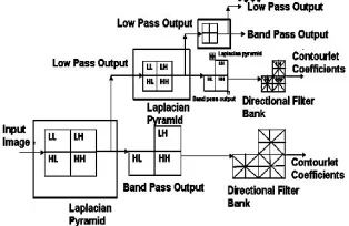
The Figure.2 illustrates the contourlet transformation, in which the input image consists of frequency components like LL (Low Low), LH (Low High), HL (High Low), and HH (High Low). The Laplacian Pyramid at each level generates a Low pass output (LL) and a Band pass output (LH, HL, and HH). The Band pass output is then passed into Directional Filter Bank, which results in contourlet coefficients [8].
Figure 2: Diagram showing the countourlet transformation.
Contourlet coefficients
Figure: 3(a): Input of barabara image; 3(b):Contoulet deformation of barabara images.
3. Methodology 3.1 Laplacian Pyramid
The basic idea of the Laplacian Pyramid is the following. First, derive a coarse approximation of the original signal, by lowpass filtering and down sampling. Based on this coarse version, predict the original (by up sampling and filtering) and then calculate the difference as the prediction error.
Figure 4: Laplacian pyramid construction
the outputs are a coarse approximation c and a difference d between the original signal and the prediction. The process can be repeated by decomposing the coarse version repeatedly.
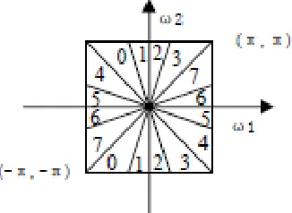
3.2 Directional filter bank (DFB)
structured decomposition that leads to 2l sub bands with wedge-shaped frequency partition as shown in Figure2
Figure 5: Directional filter construction.
The original construction of the DFB in involves modulating the input signal and using diamond-shaped filters. Furthermore, to obtain the desired frequency partition, an involved tree expanding rule has to be followed
Figure (5) shows a multiscale and directional decomposition using a combination of a LP and a DFB. Band pass images from the LP are fed into a DFB so that directional information can be captured. The scheme can be iterated on the coarse image. The combined result is a double iterated filter bank structure, named contourlet filter bank, which decomposes images into directional sub bands at multiple scales.
The contourlet transform is shift-variant and the lack of shift invariance causes pseudo-Gibbs phenomena around singularities. To achieve the shift-invariance, the Non subsampled contourlet transform is applied which built upon nonsubsampled pyramids and nonsubsampled DFB. A double filter bank structure are used for obtaining
sparse expansions for typical images having smooth contours.
In this double filter bank, the Laplacian pyramid [3] is first used to capture the point discontinuities, and then followed by a directional filter bank[4] to link point discontinuities into linear structures.
The overall result is an image expansion using basic elements like contour segments, and thus are named
contourlets. In particular, contourlets have elongated
supports at various scales, directions, and aspect ratios. This allows contourlets to efficiently approximate a smooth contour at multiple resolutions.
In the frequency domain, the contourlet transform provides a multiscale and directional decomposition.
4. Properties of the discrete contourlet
The main properties of the discrete contourlet transform are stated in the following theorem.
Theorem 1: In a contourlet filter bank, the following hold:
1) If both, the LP and the DFB use perfect-reconstruction filters, then the discrete contourlet transform achieves perfect reconstruction, which means it provides a frame operator.
2) If both, the LP and the DFB use orthogonal filters, then the discrete contourlet transform provides a tight frame with frame bounds equal to 1.
3) The discrete contourlet transform has a redundancy ratio that is less than 4/3.
4) Suppose an lj -level DFB is applied at the pyramidal level j of the LP, then the basis images of the discrete contourlet transform (i.e. the equivalent filters of the contourlet filter bank) have an essential support size of width ≈ C2j and length
≈ C2j+lj−2.
5) Using FIR filters, the computational complexity of the discrete contourlet transform is O(N) for N-pixel images.
5. Experimental Techniques
A 256*256 with 32 bit depth input image has taken. The input image has corrupted with poisons, Gaussian noise, and uniform noise respectively shown in (Fig. 6(a), 6(b) and 6(c) respectively.
Figure 6. Canonicals Images having noise (a) poisson noise; (b) Gaussian noise; (c) Uniform noise
In experimental process, there are many kinds of orthogonal wavelets and biorthogonal wavelets, we can apply 'Daubechies 9/7', '5/3', 'Burt', 'haar' and 'pkvaN' them in Contourlet transformation[5]. we chose the optical images ‘barabara.png’ of size of 256*256. The noise is the results of different image de-noising algorithm with the same directional filter (DF) ‘pkva’ under different pyramid filter (PF) combination. The combinations of pyramid filter ‘9/7’ and the directional filter ‘pkva’ gain good result (Hong Jun Hi, Zhi Min Zhang).
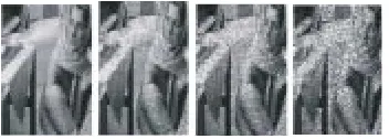
Figure 7: De-noised image 7(a), 7(b), 7(c) using wavelet transform of noisy image figure 6(a),6(b),6(c) respectively ; De-noised image 6(d), 6(e), 6(f) using contourlet transform of noisy image figure 6(a),6(b),6(c) respectively.
6. Salt and pepper noise
Represents itself as randomly occurring white and black pixels. An effective noise reduction method for this type of noise involves the usage of a median filter or a contra harmonic mean filter. barabara.png image has corrupted with salt and pepper noise density 0.01, 0.05 ,0.1 ,0.5. Noisy images are shown in Fig 8(a-d).
Figure 8: Barbara image was made noisy with salt and pepper noise with noise distribution (a) 0.01; (b) 0.05; (c) 0.1; (d) 0.2
Table 1: Image corrupted with different noise type
Table 2: (different experiment performed with salt and
pepper corrupted images with varying noise density)
Figure 9: removal of noise from corrupted image with different noise distribution using wavelet transformation. 9(a), 9(b), 9(c) and 9(d) are de-noised image of Figure 8(a), 8(b), 8(c), 8(d) in the same order.
Figure 10: removal of noise from corrupted image with different noise distribution using Contourlet transformation. 10(a), 10(b), 10(c) and 10(d) are de-noised image of Figure 8(a), 8(b), 8(c), 8(d) in the same order.
7. Spackle Noise
Speckle noise is a granular noise that inherently exists and
degrades the quality of the active images. Speckle noise in
a multiplicative noise, i.e. it is in direct proportion to the
local grey level in any area. Signal and the noise are statistically independent of each other. The sample mean and variance of a single pixel are equal to the mean and variance of the local area that is centred on that pixel. barabara.png image has corrupted with multiplicative noise density 0.01, 0.05 ,0.1 ,0.5 shown in Fig. 11(a-d)
Table 3: (different experiment performed with spackle corrupted images with varying noise density)
Figure 11: Barbara image was made noisy with spackle with noise distribution (a) 0.01; (b) 0.05; (c) 0.1; (d) 0.2
Figure 12: removal of noise from corrupted image with different noise distribution using wavelet transformation. 12(a), 12(b), 12(c) and 12(d) are de-noised image of Figure 11(a), 11(b), 11(c), 11(d) in the same order.
Spackle Noise
Expt
No. Noise Density SNR dB Of Noisy images
SNR dB De-noise Images By Wavelets
SNR dB De-noised
Image By
Contourlets
EXPT 1 0.01 12.51
dB 13.51 dB 13.37 dB
EXPT 2 0.05 5.74 dB 7.81 dB 9.51 dB
EXPT 3 0.10 2.95 dB 4.20 dB 5.53 dB
EXPT 4 0.20 0.22 dB 0.90 dB 1.69 dB
Salt & Pepper
Expt No.
Noise Density
SNR dB Noisy Images
SNR dB De-noised image wavelets
SNR dB De-noised
image by Contourlets
EXPT 1 0.01 11.83 dB 10.63 dB 13.15 dB
EXPT 2 0.05 5.86 dB 5.59 dB 8.84 dB
EXPT 3 0.10 1.84 dB 2.53 dB 4.30 dB
EXPT 4 0.20 -1.15 dB -0.75 dB -0.01 dB
Noise Type
PSNR of Noisy Image
Wavelets Contourlets
Poisson 10.9 dB 13.56 dB 13.64 dB
Gaussian 6.71dB 9.95 dB 11.58 dB
Figure 13: removal of noise from corrupted image with different noise distribution using Contourlet transformation. 13(a), 13(b), 13(c) and 13(d) are de-noised image of Figure 11(a), 11(b), 11(c), 11(d) in the same order.
8. Conclusion
The contourlet transform is one of the new geometrical image transforms, which represents images containing contours and textures Although the wavelet transform is powerful in representing images containing smooth areas separated with edges, it cannot perform well when the edges are smooth curves. New developments in directional transforms, known as contourlets in two dimensions, which have the property of capturing contours. We have performed four experiment using spackle and salt and pepper noise at different noise density 0.01, 0.05, 0.1, 0.2. We observed that SNR noise is higher in de-noised image is always higher in contoulets as compare to wavelets. for wavelet transform, the entropy of subbands in contourlet transform is much less than that of wavelet transform. Besides, the contourlet preserves better the edges than wavelet causing better PSNR. So, these two facts cause that the overall performance of contourlet transform is better for the compression of CT images.
References
[1] Guo Xujing, Wang Zulin , Nonsubsampled Contourlet Image Denoising Based on Inter-Scale Correlations[J], Journal of Opto electronics ·Laser,
2007.9,Vol 18, NO.9' 1116-1119
[2] Liang Dong, Image Enhancement Based on the Nonsubsampled Contourlet Transform and Adaptive Threshold[J], Acta elsectonica sinica, March 2008, Vol.36,No. 3: 527-530
[3] Wang Faniu, Image denoising using nonsubsampled contourlettransform[J], Computer Applications, Oct.2007, Vol.27,No.1 0:2516-519
[4] Wu Wenyi, Wu Yiquan, Method of infrared in targets detection based on Contourlet transform[J], Infrared and Laser Engineering, Feb. 2008, Vol37,No1.136-138
[5] Luo zijuan, Wu yiquan, A method of target detection in infrared image sequence based on contourlet ransform[J], sigmal processing, 2008.8, Vol24,No.4 676-679
[6] Yan Guoping, Adaptive approach to image edge detection by Laplacian of Gaussian operator
[J],Journal of Huazhong University of Science & Technology,Mar.2008, 36(3) :21-24
[7] Donoho D L. Denoise by softthresholding [J]. IEEE Transactions on Information Theory, 1995, 41: pp. 613-627.
[8] Arthur L. da Cunha, J. Zhou and Minh N. Do nonsubsampled contourlet transform:filter design and application in denoising , Image Processing, 2005. ICIP 2005. IEEE International Conference on Volume 1, 11-14 Sept. 2005 Page(s):I – 749-752 [9] R. H. Bamberger and M. J. T. Smith. A filter bank
for the directional decomposition of images: Theory and design. IEEE Trans. Signal Proc.,40(4):882–893, April 1992.
[10] M. N. Do and M. Vetterli, “The contourlet transform: An efficient directional multiresolution image representation,” IEEE Trans. Image Proc., 2005
[11] A. L. Cunha, J. Zhou, and M. N. Do, “The nonsubsampled contourlet transform: Theory, design, and applications,” IEEE Trans. Img. Proc., 2005.
[12] Li Xingmei Yan Guoping1 Chen liang, A New Method of Image Denoise Using Contourlet Transform, International Journal of Intelligent Information Technology Application, 2010, 3(1): 25-30
[13] HongJun Li, ZhiMin Zhao, Image denoising algorithm based on improved filter in Contourlet domain.
Authors Biography
Abhay P. Singh: He received his Bachelors and Masters
degree from University of Allahabad. He did his doctoral study, PhD from the same university. His interest includes swarm intelligence, digital image processing, Video processing and soft-computing. He is currently working with Institute of Engineering and Technology, MIA, Alwar.
Abhinav Mishra: He did his B.Tech(IT) from BAMS
engineering college Agra, Uttar Pradesh. He is working as Scientist-B at Doeacc center Gorakhpur. His interest includes Networking and computer architecture.
Ashish Khare: He did his PhD from Allahabad