R E S E A R C H
Open Access
Distributed execution of cognitive relaying
with time incentive: multiple PU scenario
Taskeen Nadkar
1*, Vinay Thumar
1, Uday B Desai
2and Shabbir N Merchant
1Abstract
The prime focus of this study is in developing distributed algorithms forcognitive relaying with time incentive for multiple primary users (CRTI-M).CRTI-Mis a symbiotic paradigm in which the incumbentprimary users (PUs)of the spectrum, with weak transmission links, seek cooperation from the cognitivesecondary user (SU)nodes in their vicinity, and in return reward them with anincentive timefor the latter’s own communication. When relaying through the SU network, each PU can either use its own spectrum or that of the other PUs. Cross-layer optimization problems are formulated to enable both these possibilities in a multi-hop multi-channel cognitive radio network with the objective of maximizing thecumulative time incentivefor the SUs. Corresponding distributed algorithms are developed, which face the challenge of meeting the constraints of the formulated problems with only local information and the lack of a centralized controller. Further, to make theCRTI-Mschemes practically realizable, a MAC scheduling protocol is suggested, which gives emphasis to the distributed implementation and provides a unified framework for thePUs andSUs. Simulation results are furnished to demonstrate the effectiveness of the proposed algorithms.
Keywords: Cognitive radio, Symbiotic cooperative relaying, Cross-layer optimization, Distributed algorithms, OFDM
1 Introduction
Cognitive radio (CR)attempts to alleviate the imbalance between spectrum allocation and its use, created by the
currentcommand-and-controlspectrum access policy. It
temporarily allows unused portions of the spectrum (
spec-trum holes/white-spaces), owned by the licensed users
(primary users–PUs), to be accessed by unlicensed users
(secondary users—SUs), without causing intrusive inter-ference to the former’s communication [1]. This approach can lead to a significant increase in spectrum efficiency, networking efficiency, and energy efficiency [2].
Many schools of thought have evolved from the rev-olutionary CR paradigm to accommodate substantially different technologies and solutions, one of them being
symbiotic cooperative relaying (SCR). According to this
model, the PU seeks to enhance its own
communica-tion by leveraging other users in its vicinity, having better channel conditions, as cooperative relays for its trans-mission, and in return provides suitable remuneration
to them [3-7]. The SU nodes, being scavengers of the
*Correspondence: [email protected]
1Indian Institute of Technology Bombay, Mumbai 400076, India Full list of author information is available at the end of the article
licensed PU spectrum, are potential candidates as relays. Besides, they have cognitive capabilities, which gives a large amount of flexibility of reconfiguration for resource allocation. The cooperation from the SU network results in enhanced transmission rate of the PU, which trans-lates into reduced transmission time for the same amount of information bits of the PU as those transmitted on its direct link. Then, the time saved can be offered to the SUs for their own communication as a reward for coop-erating with the PU (with a fixed rate demand). The SUs
can achieve their communication in the time incentive
without the need for spectrum sensing. The authors have previously formulated a cross-layer design to enable the
SCRscheme calledcognitive relaying with time incentive
(CRTI), for an orthogonal frequency division multiplexing (OFDM)-based multi-hop CR network [8]. The authors have also proposed that it is possible to reward the SUs
with incentive frequency bands, i.e., cognitive relaying
with frequency incentive[7,9]. While all of the aforemen-tioned works focus on providing centralized solutions to the schemes for a single PU scenario, the main concern of this article is to address a multiple PU model and propose distributed algorithms for the same.
Some unique challenges are faced when the SCR
paradigm is enabled on the spectra of multiple PUs, viz.
CRTI for multiple PUs (CRTI-M)[10,11]. The complexity
that arises in this scheme as opposed toCRTIfor a single
PU transceiver is the fact that every PU has its own dis-tinct bandwidth of operation. Consequently, it is crucial to decide the most favorable way in which the available frequency bands be utilized during the relaying process in a multi-hop multi-channel environment. We suggest two
methods of CRTI-M: band-restricted relaying (BRR), in
which each PU uses its own band when relaying through
the SU network, and all-band relaying (ABR), in which
each PU can use all the available bands (its own, as well as those of the other PUs) when relaying through the SU network. We then formulate cross-layer optimization problems which address the power allocation, frequency domain scheduling, and routing for the two proposed methods, evaluate their upper bound and devise feasible centralized solutions to them.
While the feasible centralized solutions may give rea-sonably good results in case of a small network, they will require heavy signalling overheads to communicate the global network information to a centralized node in larger CR networks. Also, the computational ability of the node may become a bottleneck. We are thus motivated to explore a solution methodology to the optimization
prob-lems for theCRTI-Mschemes, viz.ABRandBRR, that can
be distributedly implemented among the SU nodes. This is the major contribution of the article.
The proposed algorithms address the complexity of dis-tributed resource allocation in a multi-hop multi-channel SU network—an issue which is less commonly addressed in literature. The distinguishing features of the algorithm are as follows: (i) they ensure efficient utilization of the available node power by balancing the throughput along a selected path; (ii) they use a path selection metric which gives due weightage to both the throughput of the com-plete path as well as that link which may pose a bottle-neck for the path; and (iii) incase of a conflict (common resources) between the paths for multiple PUs’ sessions, the one which provides the maximum benefit is selected.
Besides, to make theCRTI-Mschemes practically
real-izable, the MAC layer scheduling and physical layer issues are approached in this article with some important con-cerns: (i) ensuring a completely distributed execution of the schemes among the SU nodes; (ii) developing a uni-fied framework for both the entities (PUs and SUs); and (iii) isolating the PUs from the operation of the SUs, like
in theCommons modelof CR. However, we do take some
liberty of allowing explicit signaling from the PUs to the
SUs initially, which happens in theproperty-rights model
(and not in the commons model) [12,13].
The article organization is as follows: (2) section describes the communication scenario and system model.
(3) section presents the centralized problem formulation
for both the CRTI-M schemes, viz.BRR andABR. The
schemes are compared in (4) section. (5) section pro-vides the details of the proposed distributed algorithms.
(6) section explains the utilization of the time
incen-tive by the SUs. (7) section furnishes the details of the
distributed implementation and MAC scheduling pro-tocol. (8) section presents simulation results and their detailed analysis. (9) section reports related work, while (10) section concludes the article.
2 System model
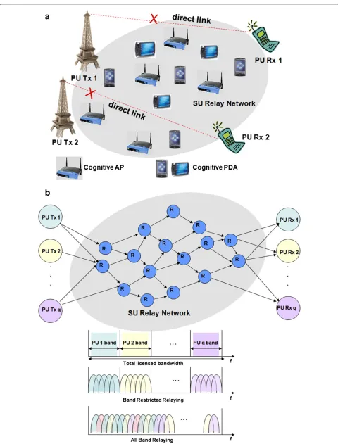
A CR system with a network of cognitive SUs and mul-tiple PU transceivers is considered (Figure 1a). Each PU has a distinct licensed bandwidth of its own. Normally, the SUs are scavenging all the PUs’ spectra for a
trans-mission opportunity. CRTI-M is enabled when one or
more PUs, with weak links, seek cooperation from the
SU network. We define Q as the set of PU transceivers
participating in the CRTI-Mscheme in a specified time
frame. OFDM is the communication technology used in the network. We have assumed unit bandwidth for each OFDM sub-carrier. The band-set of each PU is denoted
by Mq, q ∈ Q. Each PU transmitter PU Txq acts as
the source, the receiver PU Rxq as the destination, and
the SU nodes act as relays in the multi-hop communi-cation (Figure 1b). Decode-and-forward is the relaying technique at each node. The fading gains for various links are mutually independent and are modeled as zero mean complex circular Gaussian random variables. The proto-col interference model is assumed [14]. The channel gains are invariant within a frame, but vary over frames (i.e., block-fading channels). We assume that the channel gains
from eachPU Txqto the SU network, the SU network to
PU Rxq, and those among the SUs, are good enough to
provide a significantly higher end-to-end throughput as compared to the direct link of the PU transceiver, resulting in performance gains for both the PUs and SUs.
3 Problem formulation
If Ctextdirq is the throughput obtained on the direct link
between theqth PU transceiver, andCtextrelq is the
max-imum throughput achieved when relaying the qth PU’s
data through the SU network, then the time incentive
obtained for the SUs on band-setMqin a frame duration
(normalized to unity) is given by
λtq =1− Cdirq
Crelq
∀q∈Q (1)
Ideally, the incentive obtained from each PU (λtq) should
be scaled by its bandwidth (Bq) to effectively capture the
incentive obtained, i.e., λtqBq, q ∈ Q. However, since
a
b
we define the cumulative time incentive as qλtq. To
efficiently exploit the channel diversities available in the multi-hop multi-channel SU network, we allow flow split-ting, and spatial reuse of frequencies outside the interfer-ence range of nodes. The optimization problem involves a cross-layer view for power allocation, frequency band scheduling, and routing. A relay with poor channel con-ditions on all its links will be eliminated from the routes which strive to achieve maximum throughput; thus, relay selection is automatically achieved by the problem. In
the following sections, two schemes forCRTI-Mare
pro-posed.
3.1 BRR
In the firstCRTI-Mscheme, referred to asBRR, the data
from each PU are relayed on its respective frequency
band-set Mq within the SU network (Figure 1b). If we
define the communication between each unique
partici-pating PU transceiver, i.e., PUTxq−PURxq,q∈ Q, as a
session, the problem entails solving a multi-session
opti-mization with the objective of maximizing thecumulative
time incentive, i.e.,qλtq. Since each PU communicates
on its own band within the SU network, the sessions can be thought of as independent problems; hence the vari-ablesxmij,Pmij, andfij (which denote the band assignment,
power allocation, and flow, respectively) are indexed by the session number. These problems are, however, con-nected by the node power and interference constraints.
Optimization problem (P1):
We assume bidirectional links; each nodeiin the graph
has a transmit/receive set of nodesTi. fij(q) is the data
flow (bits/s) from node i to node j for the qth session.
Equation (4) indicates that, except for the source (PUTxq)
and destination (PU Rxq) nodes, the inflow into a node
is equal to the outflow. Equation (5) ensures that all the flows are non-negative. Equation (6) refers to the fact that the flows on a link cannot exceed its capacity according
to Shannon’s channel capacity theorem [15].hmij denotes
the channel power gain on band m and Pmij(q) denotes
the corresponding power allocation for theqth session. In
(6), the log function contains onlyσ2 in the
denomina-tor due to the use of an interference model, which ensures
that when node i is transmitting to node j on band m,
the interference from all other nodes in this band must remain negligible due to the frequency domain scheduling
and interference constraints.Ndenotes the node set of the
network (including PUTxq, PURxq,∀q∈Qand the SUs),
andEdenotes the edge set.
Frequency Domain Scheduling Constraints:
Equation (7) suggests that if a nodeihas used a bandm
for transmission or reception, it cannot be used by node
iagain for any other transmission or reception.xmij(q)is a binary variable which takes the value 1 if and only if band
m∈Mqis active on link(i,j), i.e.,
selected. The data transmission from nodei toj is
suc-cessful only if the received transmission power exceeds a
power thresholdPT, from which we can calculate the
min-imum required transmission power on a bandmat nodei
asPmT
ij = PT/h m
ij.Ppeakdenotes the maximum power that
can be allocated to any bandm. Equation (11) ensures that
the power consumed at nodeifor all the sessions over all
Interference constraints:
Equation (12) ensures that for a successful transmission
on linki toj, on an interfering linkkto h, the transmit
power on any bandmcannot exceedPpeakifxmij(q) = 0;
ifxmij(q)=1 then the total interference received by nodej
on bandmcannot exceed the interference thresholdPI.
Upper bound and a feasible centralized solution:
In the above formulationhmij, σ2, PT, PI, Ppeak, Pnodei
are all constants, whilexmij(q), Pijm(q), fij(q)are the
opti-mization variables. It is clearly amixed integer non-linear
programming problem. Based on the discussion on similar problems in [14,16] and the references therein, we conjec-ture that the given problem is NP-hard. A linear relaxation
of thelog term by the use of tangential supports [9] will
drastically simplify the formulation and will provide an upper bound to the original problem solution. Also, a
fea-sible sub-optimum solution can be obtained bydecoupling
the operations of power allocation and band scheduling, and that of flow computation, as follows:
(1) The power allocation and band scheduling (Pmij(q),xmij(q))are obtained from the log relaxed problem with tangential supports. This solution, however, may violate the flow constraints. (2) The above(Pmij(q),xmij(q))are substituted in the
original problem, which is then solved only with respect tofij(q)as the optimization variable. The
overall result represents a feasible solution to the original problemP1.
3.2 ABR
In the second scheme of CRTI-M calledABR, the data
from each PU can be relayed on the complete frequency band available within the SU network (which is the union of the band-sets of the participating PUs). This is unlike
BRR, where the PU’s data are relayed only on its own
band-set. The data from the various PUs are thus frequency interleaved on all available bands within the SU network
inABR(Figure 1b).
The objective is to maximize thecumulative time
incen-tiveobtained from all the PUs. Though majority of the
problem formulation forABRis similar to that forBRR,
the main difference is in the fact that in the latter the
constraints have to be posed for each PU’s band-set, while in the former the constraints are posed on the complete available band-set.
sum of the flows of all sessions on a link cannot exceed the capacity of a link according to Shannon’s channel capac-ity theorem. Furthermore, Equation (17) describes the fact
that only the PU’s own frequency band-set Mq will be
available on the first and last hops, i.e., PUTxqto the SU
network and SU network to PURxq, while within the SU
network, the total bandwidth of all the participating PUs is available.
The rest of the constraints, i.e., frequency domain scheduling, power, and interference constraints, are the
same as those posed for BRR, with Mq replaced by M
(17). However, an additional frequency domain schedul-ing constraint is introduced to ensure that a band on a given edge is not used by more than one PU. There are two reasons for incorporating this constraint: (i) It results in a much simpler formulation than if multiple PUs were allowed to use the same band; and (ii) it allows a different QoS parameter to be set for each PU if desired.
q∈Q
xmij(q)≤1 ∀(i,j)∈E,m∈M (18)
The nature of problemP1is the same as that ofP2, and consequently, the upper bound and feasible centralized
solution are computed in the same way asBRR.
4 Comparing BRR and ABR
As described earlier,ABRallows the data from each PU
to be relayed on frequency bands which do not necessar-ily belong to its own band-set, providing more channel diversity and consequently higher end-to-end
through-put for the PUs, as compared toBRR.BRR, however, has
one distinct advantage overABR—if interference
manage-ment has to be done for the individual PUs (this may be needed in case of PU prioritization, critical data trans-mission, or stringent QoS requirements), it is much easier
inBRRsince the PUs are always communicating on their
own band-set, even within the SU network. The band-set
utilized by each PU is contiguous and is knowna priori,
unlikeABR, wherein the data from the different PUs are
interleaved on all available frequency bands.
5 Distributed algorithms
Motivated by the need to diminish the communication overheads of transferring the network information to a centralized controller (which may also have limited
pro-cessing power) to solve the optimization problems forBRR
andABR, in this section we devise distributed algorithms
for the schemes.
5.1 Distributed BRR
InBRR, only the PUs’ own band-setMqis available within
the SU network while trying to maximize thecumulative
time incentive.
The algorithm comprises the following modules:
Initial-ization, Cost Computation, Path Selection, Band Assign-ment, Power Allocation, Update Allocation, and Flow Computation. Each module operates on information locally available at the SU node for its computations. First, we describe the details of each of the modules, and then explain how the modules interact in the distributed
algorithm forBRR.
Initialization:
In this module, the band allocationxmij and power
allo-cation Pmij are initialized to 0. The peak power Pmpeak
ij
is initially assigned a fixed value Ppeak, but will be later
updated based on the interference constraints. The
detec-tion thresholdPmT
ij is computed and bcost
InCost computation, we define two costs which will be
used in the path selection metric: the band cost (bcost)
and the link cost (lcost). The bcost is the inverse of the
throughput that can be achieved from the band. Thelcost
is the leastbcostfrom among all the bands on a link. Those
bands whose detection threshold exceeds the peak power
constraint are removed by making thebcostinfinite. The
computation of thebcostis different in the two events: in
case of a new allocation, thebcost is based on the peak
power (limited by the available node power); in case of an already allocated band, it depends on the difference between the allocated power and peak power (limited by the available node power).
Path Selection:
The Distributed Dijkstra’s Algorithm [17] is used to compute the least cost path onMqfrom thePU Txq
to thePU Rxq,using the metric:
Met=w1∗(i,j)∈pathlcostij+w2∗max(i,j)∈pathlcostij
If no path is found by the algorithm, found=0.
w1 and w2 are the weights assigned in the
met-ric to give the desired importance to the sum of the
lcosts and the bottleneck link (which is determined by max(i,j)∈pathlcostij). Following thepath selection, in every
iteration theband assignmentmodule assigns frequency
bands on the selected path. The algorithm exits the
cur-rent iteration when no path can be found bypath selection.
Band assignment: % Assigning the band on each link on the path
% Ensuring that the allocated band is not used again for transmission or reception
The Band assignment module consists of two main parts: assigning a band on each link of the selected path, and ensuring that the band assigned is not used again by the same node for transmission or reception (frequency domain scheduling constraints). For allocation, the band
with the leastbcostis preferred.Lset represents the
link-set of the path under consideration, in order from source to destination.Mijis the band-set on link(i,j)on the
cur-rent path. In case of a conflict on adjacent links, the band
with the next highestbcostis chosen. If that is not possible,
then the current path is revoked, and the path selection
module is used to compute a new path. It should be noted
that the variables xomik andPomik are used to denote the
band assignment and power allocation, respectively, in the current iteration, whilexmik andPmikdenote the overall
allo-cation. When a path is not found by the path selection
module, the flag foundis reset and the variablemcapis
assigned zero. The flagrevoke is reset if a suitable path
cannot be found without violating the frequency domain
scheduling constraints byband assignment.
Power allocation:
% Computing residual capacity
End For End For
% Balancing the capacity along the path
mcap=min(i,j)∈Lsetcap
% Updating peak power in view of the interference con-straints
The main objective of thepower allocationmodule is
to allocate the power based on the least capacity from
among all the links of the selected path (mcap). We first
compute the capacity based on the current allocation of
bands and power constraints. We refer to it as the
resid-ual capacity(capmij). This is because, in case the band is already allocated, it is a difference of the capacity based on the previous allocation and the current allocation. Besides balancing the capacities, the module ensures that the power constraints and interference constraints described
in the centralized problem are met. In the module,Nset
denotes the node-set of the path under consideration, and
intjis the measured interference power at nodej.
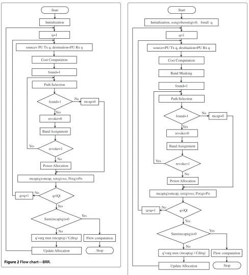
The entire algorithm with the interactions between its modules is depicted in the flow chart of Figure 2. In each
iteration, a source–destination pair (PUTxq−PURxq,q∈
Q) is selected in a round-robin manner. For each PU,
theInitialization, Cost Computation, Path Selection, Band Assignment, Power Allocation modules are executed to obtain a single path with the corresponding power allo-cation and band assignment. The power alloallo-cation and band assignment are stored but not fixed. Then the stored assignments for each PU are compared on the basis of
the minimum capacity along the path (mcap(q)). The
power allocation and band assignment for the PUTxq−
PU Rxq pair with the highest ratio of mcap(q) to Cdirq
is fixed, while the other assignments are revoked. Based
on this assignment, theupdate allocationmodule is
exe-cuted. The overall band and power allocation (xmij,Pmij) are updated with that of the current iteration (xomij,Pomij).
Update allocation:
% q represents the selected session
For alli∈N
When no paths are found for any of the sessions in a given iteration, the algorithm terminates and computes the flow.
Flow computation:
The Ford-Fulkerson algorithm [18] is used to compute the maximum network flow originating from thePU Txq,q∈Q.
Note: What is described above is what happens when the algorithm is programmed. As far as the practical dis-tributed implementation is concerned, the SUs will simul-taneously compute the assignment for all PU Txq−PU Rxq pairs. In case the path belonging to two or more pairs encounters a common node, there is a conflict in the resource allocation. In such a situation, the common node, which will have knowledge of the ‘mcaps’ of the paths pass-ing through it, will allocate the path of that PU Txq − PU Rxq pair with the ‘highest ratio of mcap(q) to Cdirq’,
while the others will be revoked.
5.2 Distributed ABR
The distributed algorithm for ABR involves the same
modules asBRR, and operates in a similar manner as the
Start
Initialization
Cost Computation
revoke=0 q=1
source= PU Tx q, destination=PU Rx q
found=1
Path Selection
found=1
Band Assignment
Power Allocation revoke=1
mcap(q)=mcap, xo(q)=xo, Po(q)=Po
q=|Q|
Sum(mcap(q))=0
q'=arg max (mcap(q) / Cdirq)
Update Allocation
Flow computation
Stop q=q+1
mcap=0 No
No
No No Yes
Yes
Yes
Yes
Figure 2Flow chart—BRR.
the total band-set of all the participating PUs, i.e.,Mˆ =
q∈QMq, is available within the SU network, while only
the PU’s own frequency band-setMqis available on the
first and last hops, i.e., PUTxqto the SU network and SU
network to PURxq.
Another difference in the distributed algorithm forABR
is the requirement of keeping the various PU’s sessions on distinct bands (as described in the corresponding
central-ized problemP2). For this purpose, an additional module
Start
Initialization, xo(q)=bcost(q)=0, forall q
Cost Computation
revoke=0 q=1
source=PU Tx q, destination=PU Rx q
found=1
Path Selection
found=1
Band Assignment
Power Allocation revoke=1
mcap(q)=mcap, xo(q)=xo, Po(q)=Po
q=|Q|
Sum(mcap(q))=0
q'=arg max (mcap(q) / Cdirq)
Update Allocation
Flow computation
Stop q=q+1
mcap=0 No
No
No No Yes
Yes
Yes
Yes Band Masking
Figure 3Flow chart—ABR.
calledBand Masking is incorporated. The details of the
module are as follows.
Band masking:
For all (i,j)∈E For allm∈M
Ifxmij(p)==1
bcostmij = ∞ End If
End For End For End For End For
Forp=q,p∈Q For alli∈N
For all (i,j)∈E For allm∈M
Ifxmij(p)==1
bcostmij =bcostmij(p) End If
End For End For End For End For
When executing the iteration for a certain PUTxq −
PURxqpair, the bands which have been utilized so far for
all the sessions except the current session are masked by
setting theirbcostto infinity. It prevents the same band
from being used by more than one session. Besides that, theupdate allocationmodule is modified accordingly.
Update allocation:
% q represents the selected session
For alli∈N For all(i,j)∈E
For all m∈M
Pmij =Pmij +Pomij(q) xmij(q)=xijm(q)OR xomij(q) xmij =xmij OR xomij(q) bcostmij(q)=bcostmij End For
End For End For
The entire algorithm with the interactions between its various modules is depicted in the flow chart of Figure 3.
6 Utilization of the time incentive
It was discussed in the previous sections that in the
CRTI-Mscheme (deployingBRRorABR), each PU takes assistance from the multi-hop network of SUs to relay its data when the link between its transmitter and receiver is
a
b
c
weak. In return, the PU rewards them with an incentive
time. As defined earlier,Cdirq is the throughput obtained
by using the weak link between PU Txq and PU Rxq,
q ∈ Q, and Crelq is the maximum throughput obtained
when relaying theqth PU’s data through the SU network.
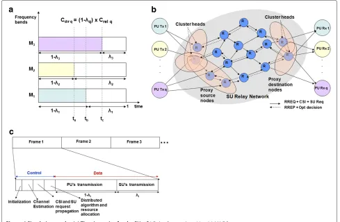
IfCdirq= (1-λtq)Crelq, 0 ≤ λtq ≤ 1, thenλtq is the time
incentiveobtained in a unit time slot on the band-setMq.
It can be observed from Figure 4a that thetime
incen-tivethat will be obtained for the SUs may be different on
the different PUs’ bands, depending onCdirqandCrelq. For
instance, in(ta−tb)onlyM2is available, while in(tb−tc)
M1M2is available. For each such interval(tx−ty) in
a frame, on the available band-set Mxy, a multi-session
sum throughput maximization problem can be solved for the SUs to efficiently exploit the transmission opportunity
createdbyCRTI-M.
7 Protocol design
7.1 Physical layer considerations
The execution of the distributed algorithms assumes the
knowledge of accuratechannel state information (CSI)at
the nodes. The estimation of local CSI is done by measur-ing the received power of the pilot signals. Discontiguous OFDM is used for data transmission, which allows the relays to decode only a fraction of the total sub-carriers.
A control channel is dedicated for all the signalling that
enables and coordinates the entireCRTI-Mscheme.
7.2 MAC layer co-ordination and distributed implementation
To make the CRTI-M scheme workable, a MAC layer
schedule is needed to co-ordinate the cross-layer activi-ties in the network. Under normal operation, each PU is communicating on its direct link, and the SUs are mon-itoring the licensed spectrum to detect a transmission opportunity. When a PU detects that its direct link is weak (based on high BER or delayed acknowledgements), it seeks cooperation from the SUs to relay its data.
Conse-quently, the PUTxqsends acooperation request (CREQq)
to the SU network (q ∈ Q, initially Q is the set of
requesting PUs). It is piggy-backed with the information of the throughput that the PU is experiencing on its weak
direct link (Cdirq). This knowledge is used in computing
thetime incentivein the given frame. The information is
received by the SUs within the radio range of each PUTxq.
We design the relaying scheme considering the fact that the PU does not have any cognitive processing
capabil-ity, and apart from the initial CREQ signaling, the PU
should be oblivious to the relaying strategy adopted by the SU network.
1 9
8 7
6
5
4
3 2
1 2
2 3 4
1
0 2.5
10
11 PU Tx 1
PU Tx 2
PU Rx 1
PU Rx 2 6.26
1 9
8 7
6 5
4
3 2
2
1 2.5
11
PU Tx 1 PU Rx 1
PU Rx 2
10
PU Tx 2
b
a
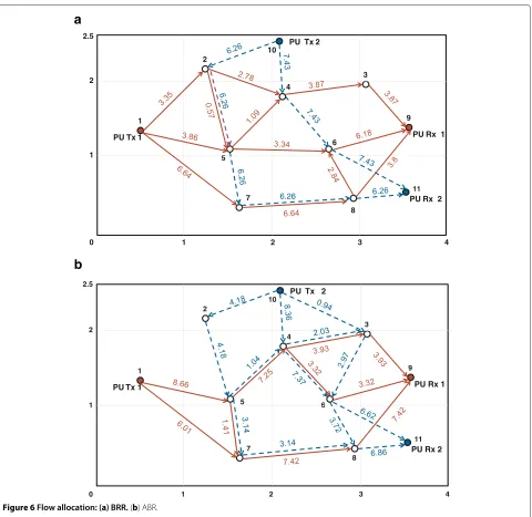
Figure 6Flow allocation: (a) BRR.(b) ABR.
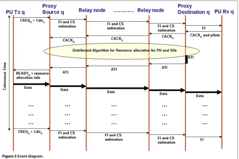
As such, it is proposed that the nodes which are in the immediate radio range of each PU transmitter act as a proxy source for the SU network (Figure 4b). CREQs from multiple PUs may be received in the control interval of the frame (the MAC frames will be explained sub-sequently). Those received in the data interval will be queued to be serviced in the control interval of the next
frame. Upon receiving the CREQq, theproxy sourcenodes
for each PU transceiver form a cluster and designate a
cluster-head PSq. Each PSq sends a frame initialization
(FI) command which is propagated throughout the SU
network to indicate the beginning of the symbiotic relay-ing. This is followed by local channel state estimation at each node.
We propose that the nodes of the last hop, which
ter-minate in the PU Rxq, form a cluster called the proxy
destinationto shield the PURxqfrom the operation of the
SU network (Figure 4b). On receiving theFI, the PURxq
responds by sending anAcknowledgement for the
Cooper-ation Request (CACKq)and pilots so that its channel can
be estimated by theproxy destinationnodes. TheCACKq
propagates through the network and reaches the proxy
source nodes to indicate that the network is ready for
CRTI-M.
Each SU node now executes the distributed algorithm
(either BRR or ABR) for resource allocation. The
Table 1 Results forBRR
Edge Frequency band Power (W)
(i,j) x(m)ij Pij(m)
neighbors is required at each node to execute the mod-ules described earlier. It is only when a node is shared by multiple sessions, that a conflict in the resource allocation arises. The common node resolves the conflict by giving
preference to the sessionq ∈ Qwith the highest ratio of
mcap(q)toCdirq.
Theproxy destinationnodes for each PU receiver also
designate a cluster-headPDq. They are designated to play
two important roles: (i) They sum themcapof every
iter-ation of the corresponding PU session, which aides the
determination of the finalCrelq, and consequently thetime
incentive λtq; (ii) if Crelq < Cdirq for any q ∈ Q, that
PU is eliminated from participating inCRTI-Mand the
algorithm is repeated for the others; and (iii) they track
the algorithm termination, in which case theAlgorithm
Termination Information (ATI)propagates on the reverse
paths towards the proxy source nodes, which in turn
inform the corresponding PUTxqto start data
transmis-sion on the allocated resources by means of theREADYq
signal. The complete event diagram with respect to each PU is depicted in Figure 5.
The proposed MAC scheduling protocol is meant to provide a unified framework for both the entities of the
CRTI-M scheme, viz. the PU and SU. If an SU has its
own data to transmit in thetime incentive, these requests
are captured in the control interval and the distributed algorithm for their sum throughput maximization is also
executed. Then in the data interval, the PU and SUs data are time division multiplexed (Figure 4c). The total time for the control interval is acceptable, provided it is a small fraction of the channel coherence time, which is true in a slow fading environment as is assumed in this study.
8 Simulation results and discussion
We have simulated a network with the nodes
ran-domly distributed in an area of 102 units as shown in
Figure 6a. Nodes 2–8 represent the SU relay nodes. Two PU transceivers have been considered: Nodes 1–9 repre-sentPU Tx1-PU Rx1and nodes 10–11 represent PUTx2−
PURx2. All the links undergo Rayleigh multi-path fading,
defined in the time domain byLl=−01hlδ(t −lT)where
hl is the complex amplitude of pathl, andLis the
num-ber of channel taps. Thelth channel coefficient between
two nodes with a distancedbetween them is distributed
asN(0, 1/dη)and the frequency domain channel is given
by its Fourier Transform. The path loss exponentη=2.5.
Each PU’s band-set comprises four OFDM bands: bands 1–4 for PU 1 and bands 5–8 for PU 2. The OFDM subcar-rier bandwidth unit is Hz. The other system parameters
areσ2= 10−4W,PT = 0.01W,PI = 0.001W,Ppeak =
0.5W,Pnodei=2W(it is the same for each nodei).
MATLAB has been used to simulate the environment and to execute the distributed algorithms. The LINGO [19] software has been used to obtain the centralized
Table 2 Results forABR
Edge Frequency band Power (W)
solutions to the BRR and ABR optimization problems. LINGO deploys the branch-and-bound technique to tackle the integer variablesx(ijm), and its nonlinear solver employs successive linear programming at each branch. For an extremely small network (one-hop, and two bands on each link), the results obtained from LINGO have been theoretically verified using the above techniques, though not included in the article. But for the network assumed in the simulation, the combinatorial nature of the problems makes it computationally prohibitive to do so.
We first report the results for the centralized solution
of the BRR problem, for a single instance of the
chan-nel conditions. The flow splitting and flow conservation are depicted in Figure 6a, where the numbers denote the flow in bits/s/Hz. The maximized sum throughput of the two PUs’ sessions is obtained as 27.54 bits/s/Hz. Table 1 reports the corresponding band assignment and power allocation. It can be observed that the session of
PUTx1−PURx1always occupies its own band-set, i.e.,
{1,2,3,4}, while the session of PUTx2−PURx2occupies
its band-set{5,6,7,8}.
The results forABR, for the same channel conditions as
those used above, are reported in Figure 6b and Table 2. The maximized sum throughput of the PUs’ sessions is obtained as 28.15 bits/s/Hz. It can be observed that the sessions occupy the complete available band-set, i.e.,
{1–8} within the SU network, but from PU Txq to the
SU network and the SU network to PU Rxq, only the
respective band sets are used.
In Figure 7, we report the cumulative time incentive
obtained in a unit time slot, i.e., qλtq, by varying
the number of PU transceivers. Cdirq was assumed as
4 bits/s/Hz for each PU, andCrelq was obtained from the
centralized cross-layer optimization results. As expected,
ABRprovides a highertime incentiveas compared toBRR.
Also, the difference in the incentive obtained from both schemes increases with the number of users. This is due to the fact that each participating PU provides its own bandwidth for use by all other PUs during the relaying
process in ABR, which results in greater channel
diver-sity as compared toBRR. These results were obtained by
adding PUs randomly to the topology described earlier; they have been averaged over three different positions of
nodes in the network (in the given area of 102units), with
10 independent channel realizations in each case, i.e., totally 30 instances. We have been unable to incorporate
any more than 4 users, as the constraint and variable
limitationin the version of LINGO used made it compu-tationally prohibitive. We anticipate that by adding more
PUs, a point will be reached beyond which thecumulative
time incentive will not increase any further—the power constraint will not allow any further increase in the relay throughput even with the addition of frequency bands.
Intuitively, this saturation will be reached earlier forBRR
as compared toABR.
The execution of the proposed distributed algorithm for
BRRis depicted iteration-wise (first four iterations) for a
single instance of the channel and two PU transceivers, in Figure 8a–d. It can be observed that on execution of the
algorithm, first a path is formed between PUTx1−PURx1.
The bands used on each link and the corresponding flow (bits/s/Hz) are indicated in the figure. In the third itera-tion, another physical path is formed between the same source–destination pair. In the fourth iteration, a path is
formed for the second session, i.e., PUTx2−PURx2. The
final allocation is shown in Figure 8e. The corresponding power allocation and band assignment are documented in Table 3.
1 2 3 4
0 0.5 1 1.5 2 2.5 3
Number of PU pairs
Cumulative Time Incentive
ABR BRR
1 9
Figure 8Execution of distributed BRR algorithm:(a)Iteration 1.(b)Iteration 2.(c)Iteration 3.(d)Iteration 4.(e)Final.
Similar results will be observed on executing the
dis-tributedABRalgorithm.
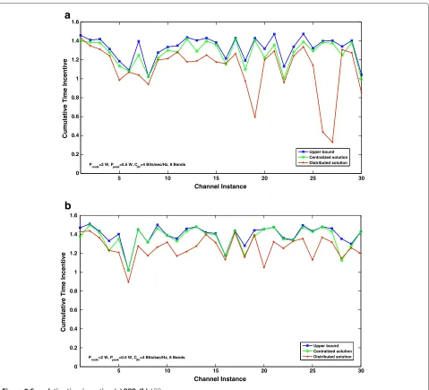
Next, we plot the cumulative time incentive for BRR
with respect to channel instances, obtained on the exe-cution of the distributed algorithm. It is compared with the upper bound obtained by tangential supports to the
logcurve and the feasible centralized solution (Figure 9a).
As expected, the centralized solution provides a higher incentive than the distributed algorithm which relies on local information. However, the solution obtained from the distributed algorithm is quite close to the central-ized result, for instance, for channel conditions 1 and 6,
the distributed result is 98.07 and 98.01% of the corre-sponding upper bound. Which means these results are even closer to the actual solution. On an average, the distributed result is 87.51% of the centralized solution. These results were plotted for two PU transceivers, and
Cdirq was assumed as 4 bits/s/Hz for each to compute the
time incentive. Similar results are observed forABR, with the distributed result being 92.4% of the corresponding centralized solution (Figure 9b).
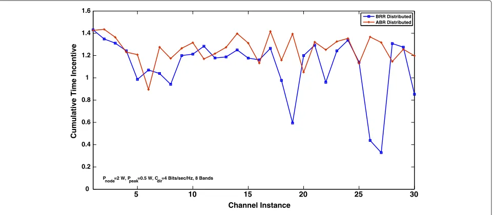
In Figure 10, we compare the distributed results
obtained for both theCRTI-Mschemes to illustrate the
5 10 15 20 25 30 0
0.2 0.4 0.6 0.8 1 1.2 1.4 1.6
Channel Instance
5 10 15 20 25 30
Channel Instance
Cumulative Time Incentive
0 0.2 0.4 0.6 0.8 1 1.2 1.4 1.6
Cumulative Time Incentive
Upper bound Centralized solution Distributed solution P
node=2 W, Ppeak=0.5 W, Cdir=4 Bits/sec/Hz, 8 Bands
Upper bound Centralized solution Distributed solution Pnode=2 W, Ppeak=0.5 W, Cdir=4 Bits/sec/Hz, 8 Bands
a
b
Figure 9Cumulative time incentive: (a) BRR.(b)ABR.
higher channel diversity it provides. This trend was also observed earlier for the centralized solutions, and further validates the proposed distributed algorithms. On an
aver-age, thetime incentiveobtained from ABRexceeds that
obtained fromBRR. In a few cases, though, the result of
ABRis lower than that forBRR, which may be attributed
to the dominating influence of the channel conditions and the limitations of the distributed algorithms as compared to the centralized.
9 Related study
We review the literature in the following contexts, which are relevant to the current work.
9.1 SCR for CR
Surrounding the concept of SCR the following models
Table 3 Results for distributedBRR
Edge Frequency band Power (W)
(i,j) x(m)ij Pij(m)
(1,2) [0 0 1 1 0 0 0 0] [0 0 0.4511 0.3876 0 0 0 0]
(1,5) [1 1 0 0 0 0 0 0] [0.2192 0.1654 0 0 0 0 0 0]
(2,3) [1 1 0 0 0 0 0 0] [0.5 0.5 0 0 0 0 0 0]
(2,5) [0 0 0 0 0 1 0 0] [0 0 0 0 0 0.0581 0 0]
(3,6) [0 0 0 0 0 0 1 1] [0 0 0 0 0 0 0.5 0.5]
(3,9) [0 0 1 1 0 0 0 0] [0 0 0.1645 0.1444 0 0 0 0]
(4,5) [0 0 0 0 0 0 0 1] [0 0 0 0 0 0 0 0.0687]
(5,6) [0 0 1 1 0 0 0 0] [0 0 0.5 0.5 0 0 0 0]
(5,7) [0 0 0 0 0 0 1 0] [0 0 0 0 0 0 0.04 0]
(5,8) [0 0 0 0 1 0 0 0] [0 0 0 0 0.5 0 0 0]
(6,9) [1 1 0 0 0 0 0 0] [0.5 0.5 0 0 0 0 0 0]
(6,11) [0 0 0 0 1 1 0 0] [0 0 0 0 0.4471 0.2961 0 0]
(7,8) [0 0 0 0 0 1 0 0] [0 0 0 0 0 0.5 0 0]
(8,11) [0 0 0 0 0 0 1 1] [0 0 0 0 0 0 0.1853 0.1224]
(10,2) [0 0 0 0 0 0 0 1] [0 0 0 0 0 0 0 0.5]
(10,3) [0 0 0 0 1 1 0 0] [0 0 0 0 0.2227 0.1893 0 0]
(10,4) [0 0 0 0 0 0 1 0] [0 0 0 0 0 0 0.2333 0]
by AF relaying of the PU’s data by multiple cooperating SUs. All of the aforementioned works in literature have considered either a single relay node or single channel CR networks. The authors have also contributed
signif-icantly towardsSCRparadigms for channel
multi-hop networks [7-11], the details of which are provided in (1) section.
9.2 Cross-layer optimization for multi-channel networks
Cross-layer optimization problems have received consid-erable attention in literature ([14-22] and the references therein). Shi et al. [14] have addressed power control, frequency band scheduling, and flow routing for the
physical modelin a multi-hop multi-channel CR network with the objective of maximizing the rates of a set of user communication sessions. The power is quantized to a finite number of levels, and a centralized solution
is developed using the branch-and-bound framework.
Ma and Tsang [21] use a similar model but a simplistic problem formulation, with the assumption of uniform power and only band assignment and flow routing as the variables. The formulation of Zhang et al. [16] aims at minimizing the transmission time for the user sessions by joint consideration of spectrum allocation, routing, and time scheduling. Besides these, there also exist cross-layer formulations for conventional multi-channel wireless net-works with all or some of the flow, scheduling, power con-straints, typically with the objective of maximizing users’ throughput, or minimizing power consumption [22-24].
9.3 Distributed algorithms for cross-layer formulations
The work pertaining to distributed algorithms for cross-layer optimization problems is limited. Lin and Shroff [25] consider maximizing the sum of the users’ utility func-tions, assuming a single path for each user and a single channel network, to determine the rate and link schedule. Palomar and Chiang [26] also formulate a similar problem within a power constrained situation, which they address using different decomposition techniques. Lin and Rasool [27] have developed a distributed algorithm that jointly
5 10 15 20 25 30
0 0.2 0.4 0.6 0.8 1 1.2 1.4 1.6
Channel Instance
Cumulative Time Incentive
BRR Distributed ABR Distributed
P
node=2 W, Ppeak=0.5 W, Cdir=4 Bits/sec/Hz, 8 Bands
solves the channel-assignment, time scheduling and rout-ing problem to maximize the system capacity, with fixed power, in a multi-channel network. Joint allocation of power, frequency bands, and routing in a multi-channel multi-hop network in a distributed manner is more chal-lenging. The centralized framework suggested by Shi et al. [28] is quite similar to ours, hence we feel the need to provide a detailed comparison with the former. The main difference in the cross-layer formulations is that this study
incorporates the requirements ofBRR(each PU relaying
on its own band) andABR(each PU utilizing all the
avail-able bands), while that of Shi et al. is concerned with throughput maximization of SUs’ sessions. Also, we con-sider the sum interference from all the neighboring nodes for power allocation. The distributed algorithm described by Shi et al. differ from ours in the following aspects: (i) the
metric used by the former for path selection isbandwidth
footprint productwhich targets optimal spatial occupancy, whereas the authors use a metric which gives weightage to both the net throughput that can be obtained from a path and also that link which may pose a bottleneck, which seems more appropriate in a throughput maximization
scenario; (ii) the former’s strategy involves aConservative
Iteration Process, which allocates resources for the
ses-sions and anAggressive Iteration Process, which tries to
increase the throughput of sessions with lower throughput (lower scaling factors) by releasing the allocated resources of the others with higher throughput. The authors, on the other hand, propose that on encountering paths from multiple sessions, a common node will instantaneously resolve the conflict by giving preference to that session which is likely to derive a higher benefit—this approach befits a distributed implementation in terms of practical execution and time; (iii) given the fact that the source and destination are PUs, while the relay nodes are SUs, the exchange of information between the two entities is rather restricted. In this study, the detailed MAC schedule is pro-vided, which will address this issue while facilitating the distributed algorithm for resource allocation. In the work of Shi et al., there is no such concern since only one entity, viz. the SU is involved in the process; (iv) the algorithm of Shi et al. allocates power on unused bands based on the detection threshold which results in the same metric for all bands irrespective of the channel gains. On the other hand, the proposed algorithm operates on the peak power, which gives importance to the gains when selecting high throughput paths. Moreover, the proposed algorithm is more meticulous in meeting the constraints of the central-ized problem, and has specialcentral-ized modules to account for
BRRandABR.
10 Conclusion
The main focus of this article is to develop distributed
algorithms for the two methods ofCRTI-M, viz.BRRand
ABR.ABRwhich allows a PU to use all other PUs’ bands
when relaying through the SU network provides a higher
cumulative time incentivefor the SUs.BRR, on the other hand, which allows every PU to only use its own band, makes management and PU prioritization easier. The pro-posed distributed algorithms are meticulous in meeting the constraints of the corresponding centralized problems and the results are in close proximity of the centralized results. A MAC scheduling protocol is described which gives emphasis to the distributed implementation and presents a unified framework for the PUs and SUs.
Competing interests
The authors declare that they have no competing interests.
Acknowledgements
This study was supported by the Ministry of Communication and Information Technology, Government of India, New Delhi. The study was also supported by the Microsoft Corporation and Microsoft Research India under the Microsoft Research India PhD Fellowship Award 2009. A small part of this study (only the centralized problem formulation) has been presented at IEEE VTC Fall 2011.
Author details
1Indian Institute of Technology Bombay, Mumbai 400076, India.2Indian
Institute of Technology Hyderabad, Hyderabad 502205, India.
Received: 9 February 2012 Accepted: 28 September 2012 Published: 2 November 2012
References
1. S Haykin, Cognitive radio: brain-empowered wireless communications. IEEE Trans. Sel. Areas Commun.23, 201–220 (2005)
2. H Zhang, Cognitive radio networking for green communications and green spectrum. [Online] Available from http://www.comnets.org/ keynote.html
3. O Simeone, Y Bar-Ness, U Spagnolini, inCooperative Wireless
Communications, ed. by Y Zhang, H Chen, and M Guizani. Cooperative
cognitive radio (Auerbach Publications, CRC Press, Boca Raton, 2009), pp. 209–230
4. J Zhang, Q Zhang, inProc. of ACM MobiHoc,Stackelberg game for utility-based cooperative cognitive radio networks (2009), pp. 23–32 5. P Xue, P Gong, N Cao, DK Kim, inProc. of KICS the 18th, JCCI,Symbiotic
architecture for the cognitive radio networks with amplify-and-forward relaying cooperation (Jeju, Korea, 2009), pp. 49–54
6. P Gong, JH Park, JM Yoo, Y Bo-Sun, DK Kim, inProc. of 4th International
Symposium on Wireless Pervasive Computing,Throughput maximization
with multiuser non-selfish cognitive relaying in CR networks (2009), pp. 1–5
7. T Nadkar, V Thumar, UB Desai, SN Merchant, Symbiotic cooperative relaying in cognitive radio networks with time and frequency incentive. Springer Telecommun. Syst. J.: Special Issue on Mobile Computing and Networking Technologies. doi:10.1007/s11235-011-9494-4
8. T Nadkar, VM Thumar, UB Desai, SN Merchant, inProc. of IEEE Symp. on
New Frontiers in Dynamic Spectrum Access Networks (DySPAN),A cross-layer
framework for symbiotic relaying in cognitive radio networks (2011), pp. 498–509
9. T Nadkar, VM Thumar, G Shenoy, UB Desai, SN Merchant, inProc. of the
IEEE Global Telecommunications Conference, IEEE GLOBECOM,Cognitive
relaying with frequency incentive (2011), pp. 1–6
10. T Nadkar, VM Thumar, G Shenoy, UB Desai, SN Merchant, inProc. of IEEE Symposium on Personal, Indoor and Mobile Radio Communications (PIMRC), Cognitive relaying with time incentive:protocol design for multiple primary users (2011), pp. 577–582
11. VM Thumar, T Nadkar, G Shenoy, UB Desai, SN Merchant, inProc. of IEEE
Vehicular Technology Conference (VTC),Cognitive relaying with time
incentive: multiple primary users (2011), pp. 1–5
13. W Lehr, J Crowcroft, inProc. of First IEEE Symp. New Frontiers in Dynamic
Spectrum Access Networks,Managing shared access to a spectrum
commons (2005), pp. 420–444
14. Y Shi, Y Hou, S Kompella, inProc. of IEEE MILCOM’08,A cross-layer approach to multi-hop networking with cognitive radios (2008), pp. 1–7 15. TM Cover, Thomas JA,Elements of Information Theory, 2nd edn.
(Wiley-Interscience, New York, 2006)
16. J Zhang, Z Zhang, H Luo, A Huang, inProc. of the IEEE Global
Telecommunications Conference, IEEE GLOBECOM,A column generation
approach for spectrum allocation in cognitive wireless mesh network (2008), pp. 1–5
17. PA Humblet, An adaptive distributed, Dijkstra shortest path algorithm. Technical Report CICS-P-60, Center for Intelligent Control Systems, MIT, (1981)
18. TH Cormen, CE Leiserson, RL Rivest, C Stein, 2nd edn. (MIT Press and McGraw-Hill, 2001), pp. 651–664
19. LINGO: User’s guide (LINDO Systems Inc., 2006)
20. DP Bertsekas,Network Optimization—Continuous and Discrete models (Athena Scientific, Belmont, MA)
21. M Ma, DHK Tsang, inProc. of 5th IEEE Consumer Communications and
Networking Conference CCNC,Joint spectrum sharing and fair routing in
cognitive radio networks (2008), pp. 978–982
22. R Bhatia, MS Kodialam, inProc. of IEEE INFOCOM,On power efficient communication over multi-hop wireless networks: joint routing, scheduling and power control (2004), pp. 1457–1466
23. M Alicherry, R Bhatia, L Erran Li, Joint channel assignment and routing for throughput optimization in multiradio wireless mesh networks. IEEE J. Sel. Areas Commun.24(11), 1960–1971 (2006)
24. K Karakayali, JH Kang, M Kodialam, K Balachandran, inProc. of IEEE ICC, Joint resource allocation and routing for OFDMA-based broadband wireless mesh networks (2007), pp. 5088–5092
25. X Lin, NB Shroff, inProc. IEEE Infocom,The impact of imperfect scheduling on cross-layer rate control in wireless networks Miami, 2005),
pp. 1804–1814
26. DP Palomar, M Chiang, inProc. IEEE Infocom,Alternative decompositions for distributed maximization of network utility: framework and applications Spain, 2006), pp. 1–13
27. X Lin, S Rasool, inProc. IEEE Infocom,A distributed joint
channel-assignment, scheduling and routing algorithm for multi-channel ad hoc wireless networks Anchorage, 2007), pp. 1118–1126
28. Y Shi, Y Thomas Hou, H Zhou, S Midkiff, Distributed cross-layer optimization for cognitive radio networks. IEEE Trans. Veh. Technol. 59(8), 4058–4069 (2010)
doi:10.1186/10.1186/1687-1499-2012-332
Cite this article as:Nadkaret al.:Distributed execution of cognitive relaying
with time incentive: multiple PU scenario.EURASIP Journal on Wireless
Com-munications and Networking20122012:332.
Submit your manuscript to a
journal and benefi t from:
7Convenient online submission
7Rigorous peer review
7Immediate publication on acceptance
7Open access: articles freely available online
7High visibility within the fi eld
7Retaining the copyright to your article