New DC Voltage Balancing Technique for High Power Multilevel
Converter
E Surya Narayana1 G venkateswara Rao2
M.Tech Student, Department of EEE, KIET-II, Kakinada, India.1 Asst. Professor, Department of EEE, KIET-II, Kakinada, India.2
Abstract-In this venture, a dedicated pulse width modulation (PWM) procedure particularly intended for single-stage (or four wire three-stage) multilevel Cascaded H-Bridge Converters is displayed. The point of the proposed method is to limit the DC-Link voltage unbalance, autonomously from the adequacy nof the DC-Link voltage reference, and remunerate the exchanging gadget voltage drops and on-state resistances. Such remuneration can be utilized to accomplish an expansion in the waveform nature of the converter. This is especially valuable in high-control low supply voltage applications where a low exchanging recurrence is utilized. The DC-Link voltage adjusting capacity of the strategy expels the prerequisite for extra control circles to effectively adjust the DC-Link voltage on every H-Bridge, streamlining the control structure. In this venture fuzzy controller is utilized to decrease the aggregate consonant twisting. The proposed balance procedure has been approved using reproduction comes about.
Key words- DC Voltage, H- Bridge, PWM.
I.INTRODUCTION
As of late multilevel converters have been distinguished as a favored topology for high power applications accordingly of points of interest, for example, abnormal amounts of particularity, accessibility, general productivity, and high yield waveform quality. This is accomplished to the detriment of expanded quantities of segments and control multifaceted nature. In electrical footing drives multilevel inverters have been effectively connected with a specific end goal to enhance framework unwavering quality and decrease disappointments on engine windings subsequently of the lower normal mode voltages that they create. Similar points of interest can be accomplished when connected to Hybrid Electric Vehicles. Notwithstanding this usefulness, when the dc side is associated with an arrangement of batteries or other vitality stockpiling gadgets the multilevel converter can be utilized to keep up the charge adjust of the vitality stockpiling framework. Multilevel converters have likewise been connected for power quality change and
FACTS where, particularly in aviation applications, the decreased sifting prerequisite required for multilevel converter speaks to leeway as far as aggregate converter weight and cost. In the coming years, multilevel converters are probably going to be utilized progressively in electrical power frameworks with a specific end goal to accomplish a higher adaptability and dependability and permit shrewd power administration within the sight of various vitality sources and utilities associated with the network. An illustration is the substitution of circulation level substation transformers with high power multilevel consecutive converters. In all the previously mentioned applications, multilevel converters are as a rule progressively considered as a key innovation, subsequently of their ability to deal with high-control, using low voltage control gadgets, while keeping up unrivaled quality yield waveforms, even at low gadget exchanging recurrence. Among all the conceivable multilevel converter topologies, Cascaded H-Bridge converters (CHB) speak to a fascinating arrangement in a few applications where its diminished number of parts when contrasted with other multilevel converter topologies and high measured quality are essential elements which loan themselves to the change of general framework proficiency and dependability. Despite the fact that three-stage converters are generally utilized as a part of high power applications, a solitary stage arrangement is to a great extent utilized in Photovoltaic inverters, footing applications or in impartial associated three-stage control dissemination frameworks.
The primary issues with the CHB converter is the prerequisite for segregated DC-Link voltages and additionally the noteworthy impact of gadget voltage drop and on-state resistance in applications with high number of levels and generally low application air conditioning side voltages. Moreover, in the dynamic rectifier arrangement, adjusted DC-Link voltages are required to accomplish ideal operation considering a symmetrical (and accordingly completely particular) setup. DC-Link voltage adjusting strategies have been proposed in writing for CHB dynamic rectifiers and they can be partitioned into two primary gatherings relying upon whether the DC-Link voltage adjusting strategy is
New DC Voltage Balancing Technique for High Power Multilevel
Converter
E Surya Narayana1 G venkateswara Rao2
M.Tech Student, Department of EEE, KIET-II, Kakinada, India.1 Asst. Professor, Department of EEE, KIET-II, Kakinada, India.2
Abstract-In this venture, a dedicated pulse width modulation (PWM) procedure particularly intended for single-stage (or four wire three-stage) multilevel Cascaded H-Bridge Converters is displayed. The point of the proposed method is to limit the DC-Link voltage unbalance, autonomously from the adequacy nof the DC-Link voltage reference, and remunerate the exchanging gadget voltage drops and on-state resistances. Such remuneration can be utilized to accomplish an expansion in the waveform nature of the converter. This is especially valuable in high-control low supply voltage applications where a low exchanging recurrence is utilized. The DC-Link voltage adjusting capacity of the strategy expels the prerequisite for extra control circles to effectively adjust the DC-Link voltage on every H-Bridge, streamlining the control structure. In this venture fuzzy controller is utilized to decrease the aggregate consonant twisting. The proposed balance procedure has been approved using reproduction comes about.
Key words- DC Voltage, H- Bridge, PWM.
I.INTRODUCTION
As of late multilevel converters have been distinguished as a favored topology for high power applications accordingly of points of interest, for example, abnormal amounts of particularity, accessibility, general productivity, and high yield waveform quality. This is accomplished to the detriment of expanded quantities of segments and control multifaceted nature. In electrical footing drives multilevel inverters have been effectively connected with a specific end goal to enhance framework unwavering quality and decrease disappointments on engine windings subsequently of the lower normal mode voltages that they create. Similar points of interest can be accomplished when connected to Hybrid Electric Vehicles. Notwithstanding this usefulness, when the dc side is associated with an arrangement of batteries or other vitality stockpiling gadgets the multilevel converter can be utilized to keep up the charge adjust of the vitality stockpiling framework. Multilevel converters have likewise been connected for power quality change and
FACTS where, particularly in aviation applications, the decreased sifting prerequisite required for multilevel converter speaks to leeway as far as aggregate converter weight and cost. In the coming years, multilevel converters are probably going to be utilized progressively in electrical power frameworks with a specific end goal to accomplish a higher adaptability and dependability and permit shrewd power administration within the sight of various vitality sources and utilities associated with the network. An illustration is the substitution of circulation level substation transformers with high power multilevel consecutive converters. In all the previously mentioned applications, multilevel converters are as a rule progressively considered as a key innovation, subsequently of their ability to deal with high-control, using low voltage control gadgets, while keeping up unrivaled quality yield waveforms, even at low gadget exchanging recurrence. Among all the conceivable multilevel converter topologies, Cascaded H-Bridge converters (CHB) speak to a fascinating arrangement in a few applications where its diminished number of parts when contrasted with other multilevel converter topologies and high measured quality are essential elements which loan themselves to the change of general framework proficiency and dependability. Despite the fact that three-stage converters are generally utilized as a part of high power applications, a solitary stage arrangement is to a great extent utilized in Photovoltaic inverters, footing applications or in impartial associated three-stage control dissemination frameworks.
coordinated in the controller, utilizing extra control circles, or straightforwardly into the modulator. In this venture, the last case is viewed as and a novel balance procedure, produced for single-stage frameworks and reasonable for high power multilevel CHB converters, is presented. The proposed regulation procedure depends on the Distributed Commutation Modulator (DCM), depicted in. DCM is a heartbeat width regulation (PWM) strategy particularly intended for multilevel CHB converters. The point of DCM is to limit the recompense recurrence of the individual gadgets, circulating these compensations equally among the converter HB cells. Accordingly, the converter misfortunes are similarly conveyed over the gadgets, expanding the converter unwavering quality, without trading off the yield voltage waveform quality.
However, the balancing of the DC-Link voltages represents an issue for the DCM strategy as such a technique is able to passively balance the DC Link voltages only when balanced dc currents are demanded. Moreover, in the DCM technique, the devices voltage drops and on-state resistances are not considered. In order to overcome these issues, an active DC-Link voltage balancing algorithm has been designed for DCM which accounts for the device voltage drops and on-state resistances, improving the output voltage waveform quality and maintaining good performances even when unbalanced dc currents are demanded. In the concept of DC-Link voltage balancing algorithm is introduced as well as the device voltage drop and on-state resistance compensation. The main target of the proposed modulation strategy is, in contrast with DCM, to minimize the DC-Link voltage unbalance among the different converter cells in order to maintain the converter modularity and produce high quality waveforms, even if a low switching frequency is considered. Referring to Fig. 1, the DC-Link voltage affects the distribution of the commutations among the devices only for unbalanced loads, i.e., whenR1=R2=R3. When the loads are balanced, i.e., whenR1=R2=R3, the device commutations are equally distributed among the CHB cells. When compared to other DC-Link voltage balancing techniques, the proposed algorithm presents a very fast and accurate response, avoiding the use of
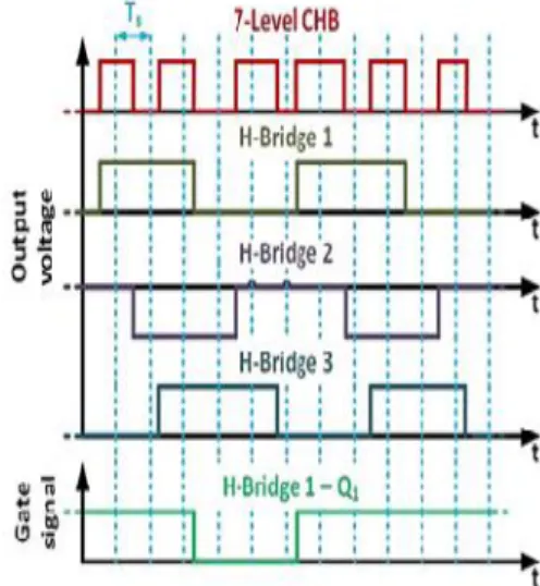
additional control loops. The gadget voltage drops and on state resistances are likewise adjusted, delivering higher quality yield voltage waveforms, specifically, in applications where countless cells are utilized with a generally low target air conditioning side waveform extent, i.e., car applications. The proposed modulator is executed on a solitary stage 7-level CHB, containing three H-Bridges cells, which is generally utilized as a part of Photovoltaic inverters or in unbiased associated three-stage control circulation frameworks. Points of interest of the proposed tweak strategy are given in Section III, including cases of the operation of the proposed procedure and a short clarification of the DCM technique. The got results are depicted in detail, highlighting the preferences and drawbacks of the proposed balance method.
II. CASCADED H-BRIDGE CONVERTERS
In a solitary stage 7-level CHB converter, associated as a dynamic rectifier, is appeared. In spite of the fact that the proposed strategy is similarly as successful in the inverter mode arrangement, keeping in mind the end goal to test the capacity of a DC-Link voltage adjusting calculation and stay away from the need of secluded high voltage sources, the rectifier design is favored. Alluding to Fig. 1, the HBs are arrangement associated on the network side and an inductive channel L, with a parasitic resistance rL, is utilized to encourage the required association between the converter and the matrix. Every HB cell is associated with a capacitor, C, and a resistor, R, used to speak to the stacking of the converter, which in all actuality could conceivably be another converter, giving consecutive operation, or a genuine load. For a symmetrical converter, the geneticist cell is associated with a voltage source and can create three voltage levels, showed as−VDCi, 0 and +VDCi. These voltage levels are related,
separately, to states−1, 0 and 1. As a result, a n-cell fell converter can produce2n+1voltage levels on the air conditioner side. The yield voltage VCONV is made out of seven diverse voltage levels which can be delivered by at least one blends of H-Bridge states, as demonstrated in Table I.
III. PROPOSED MODULATION TECHNIQUE
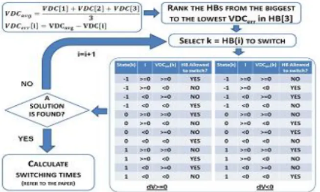
proposed calculation is to even out the voltages on the capacitors, their normal esteem is considered as the reference voltage for every DC-connect capacitor in the calculation, while the aggregate DC-Link voltage is set to the reference esteem utilizing a Proportional-Integral activity outside to the modulator. With a specific end goal to diminish weight on the power switches and enhance their unwavering quality, the recompenses are allowed just between nearby voltage levels i.e., it is conceivable to switch just a single leg of one H-Bridge cell amid each inspecting interim. The calculation is particular and appropriate to a genericn-level CHB converter; however expanding the quantity of voltage levels requires a conspicuous increment in computational exertion.
Fig :2 Overall control scheme
A. Control Scheme
Fig. 2, demonstrates the control piece outline executed for the converter of Fig. 1, where VDC signifies the aggregate DC-Link voltage and VDC∗ is the coveted DC-Link voltage. A solitary stage Phase-Locked-Loop (PLL) is utilized as a part of the control plan to get the
supply stage point, θ, and RMS esteem, Vs,RMS. The
PLL plan is gotten by falling the orthogonal framework generator proposed in [37], in view of the Second Order Generalized Integrator, with the three-stage PLL displayed in [38], in light of an unfaltering state straight Kalman channel.
The line current is controlled keeping in mind the end goal to acquire the required DC-Link voltage; to accomplish this objective, the present reference I ∗ is ascertained, at each testing period Ts of the controller, as takes after
The control output represents the desired converter voltage average value during the next sampling interval, applied using the proposed modulation scheme.
B. Distributed Commutation Modulator (DCM)
As specified in the presentation, the proposed procedure can be viewed as a change to the DCM strategy where the recompenses are disseminated among the three H-Bridges with a specific end goal to decrease the gadget exchanging recurrence, and improve the converter misfortunes. Under ordinary working conditions, the n converter cells can commutate consecutively so that every one can perform just a single substitution each n testing periods. Recompenses are allowed just between adjoining voltage levels.
delivered and the regulation calculation endeavors to circulate the compensations
among the gadgets. Two primary issues have been distinguished utilizing this strategy. The DC-Link voltage adjust is accomplished with a symmetrical load on the three HBs and in some other case an extra control is required. The second issue shows up on account of high-power yet moderately low voltage applications using an extensive number of CHB cells, where the gadget voltage drops and on-state resistances can contrarily influence the conduct of the modulator. An extra calculation, depicted beneath, has been actualized to conquer these issues.
C. Gadget Voltage Drop and on-State Resistance Compensation
The gadget voltage drop and on-state resistance impact is remunerated considering, rather than the deliberate DC-Link voltages, the successful voltages produced by the converter [43]. For every HB cell, three parasitic voltages, which are reliant on the present course and plentifulness, are characterized as
In (3)–(5) the actual voltages generated by the converter are calculated on the basis of the diode and transistor voltage drops (Vd,Vq), the diode and transistor on state resistances(Rd,Rq), and on the current I flowing through the HB.
Fig :4.3 DC voltage balancing basic principle In particular, when a zero voltage state is applied, the voltage VDCef f produced at the output of the ith cell is defined by the following equation:
On the other hand, in case of positive power flowing through the HB cell (applied voltage and ac current have the same sign) the transistor are on and generate the voltage defined by the following equation
Similarly, in case of negative power flow through the HB cell, the transistors are on and generate the voltage defined as follow
DC link voltage control algorithm was explained in the project[1]
IV. FUZZY CONTROLLER
The word Fuzzy means ambiguity. Fluffiness happens when the limit of snippet of data is not obvious. In 1965 Lotfi A. Zahed propounded the fuzzy set hypothesis. Fuzzy set hypothesis displays huge potential for powerful tackling of the instability in the issue. Fuzzy set hypothesis is an incredible numerical apparatus to deal with the vulnerability emerging because of unclearness. Understanding human discourse and perceiving manually written characters are some normal occasions where fluffiness shows.
Fuzzy set hypothesis is an expansion of established set hypothesis where components have shifting degrees of participation. Fuzzy rationale utilizes the entire interim in the vicinity of 0 and 1 to portray human thinking. In FLC the information factors are mapped by sets of participation capacities and these are called as "Fuzzy SETS".
Fig.4a. Fuzzy Basic Module
V.SIMULINK MODELLING AND RESULTS
Simulations have been carried out in order to compare the performance of the proposed modulation strategy. The power rating of the converter considered in simulation match the power rating used in the experimental tests (3 kW). Operation in rectifier mode has been used to avoid the requirement of isolated high voltage sources. The proposed method, however, is equally as effective in the inverter mode configuration. A Dead-Beat current control, described in, is used to impose the desired voltage reference. The complete control scheme is shown in Fig. 3 while the simulation parameters are shown in Table II. In order to highlight the effect of parasitic components, large values of Vd and Vq are considered during simulations. In this project, the proposed modulator is compared with the DCM technique illustrated . A comparison between the DCM technique and other well-known modulation techniques for CHB converters has already been carried out. In Fig. 6.4 (a) and (b) it is possible to appreciate that the total DC-Link voltage is correctly regulated at the reference value with an optimal DC-Link voltage balance. However, with the proposed modulation strategy the DC-Link voltage oscillations are reduced, when compared to those observed with DCM. In Fig.6.5 (c) and (d) the line current and the grid voltage are shown for a switching frequency of 1.25 kHz. For the proposed technique the current is correctly regulated with the required phase alignment between grid voltage and current. The proposed modulation strategy also produces a lower total harmonic distortion (THD) value, compared with DCM, due to the active compensation of device voltage drops and on-state resistances which reduces the line current distortion. Fig. 6.4 (e) and (f) illustrate, for both techniques, the converter output voltage versus the converter voltage reference and the voltages produced by the single HBs. The commutations are equally distributed among the HBs for both modulation strategies. In order to appreciate the superior capability of the DC-Link voltage balancing of the proposed modulation strategy,
three unbalanced dc loads of 10 Ω–20Ω–30Ω are
implemented in the simulation. Such operating conditions frequently occur in solid state transformers as well as in
battery supplied inverters. From Fig. 6.5 (a) and (c), which illustrate the DC-Link voltages, it is possible to observe that for the proposed modulation strategy the total DC-Link voltage is correctly regulated and the single DC-Link voltages are well balanced. When using the DCM technique under the same conditions, an unbalance of the DC-Link voltages is clear.
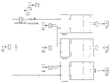
The below figure is the schematic diagram of a CHB multilevel inverter and its control diagram.
Fig: 5.1schematic diagram of a CHB multilevel inverter
Fig: 5.3 Fuzzy Controller SIMULATION results for Fuzzy Controller
Fig: 5.4. Simulation results with dc Link voltage balancing algorithm, devices voltage drops and on-state
resistances compensation
Fig: 5.5. Simulation results with dc Link voltage balancing algorithm, devices voltage drops and on-state
resistances compensation
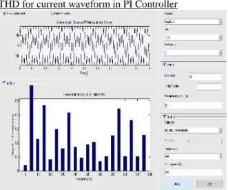
THD for current waveform in PI Controller
Comparison for THD in both PI Controller and FUZZY Controller
PI Controller FUZZY Controller
3.29 0.37
In Fig. 5.4(c) and (d) the line current and grid voltage are shown for a switching frequency of 1.25 kHz: using the proposed technique the current is correctly regulated with the required phase alignment between grid voltage and current. On the contrary, the DCM technique produces a significant distortion on the line current. The proposed modulation strategy clearly generates a lower THD value, compared with DCM. Fig. 5.4(e) and (f) illustrate, for both techniques, the converter output voltage versus the converter voltage reference as well as the voltages produced by the single HBs. Using the proposed strategy the commutations are not evenly distributed among the HBs anymore. Conversely, using the DCM technique, the even commutation distribution is maintained but the significant harmonic content affects the Dead-Beat controller, producing a distorted voltage reference.
CONCLUSION
In this project, a new modulation concept, suitable for high power low switching frequency cascaded multilevel converters, is introduced. In order to minimize the switching frequency, only one leg of a single H-Bridge cell in each sampling interval is commutated, obtaining a total switching frequency that is the half of the sampling frequency. The aim of the presented modulation technique is to minimize the unbalance of the DC link voltages, for any amplitude of the voltage reference, in order to obtain high quality waveforms while maintaining the modularity of the converter. In order to obtain a quick response to unbalance on the dc loads, the balancing algorithm is fully integrated into the modulation scheme without using any additional controllers. The proposed modulation technique provides a balance of the DC-Link voltages without compromising the quality of the
waveforms, in term of harmonic distortion, with both balanced and unbalanced dc loads. The modulator also naturally distributes the commutations among the H-Bridge cells in case of balanced dc loads. In conclusion, using the proposed technique, it is possible to achieve an optimal balance of DC-link voltages and an active compensation for device parasitic effects in an n-level CHB active rectifier with any configuration of the dc loads, improving the quality of the ac waveforms and maintaining the modularity of the converter. Fuzzy controller is used to reduce the total harmonic distortion. The results were analyzed in MATLAB/SIMULINK environment
REFERENCES
[1] Luca Tarisciotti, Member, IEEE, Pericle Zanchetta,
Member, IEEE, Alan Watson, Member, IEEE,” Active
DC Voltage Balancing PWM Technique for High-Power
Cascaded Multilevel Converters”. IEEE
TRANSACTIONS ON INDUSTRIAL ELECTRONICS, VOL. 61, NO. 11, NOVEMBER 2014
[2] J. S. Lai and F. Z. Peng, “Multilevel converters-a new
breed of power converters,”IEEE Trans. Ind. Appl., vol.
32, no. 3, pp. 509–517, May/Jun. 1996.
[3] L. Harnefors and A. Antonopoulos, “Dynamic analysis of modular multilevel converters,” IEEE Trans. Ind. Electron., vol. 60, no. 7, pp. 2526–2537, Jul. 2013.
[4] L. M. Tolbert and F. Z. Peng, “Multilevel converters for large electric drives,”IEEE Trans. Ind. Appl., vol. 35,
no. 1, pp. 36–44, Jan./Feb. 1999.
[5] C. Cecati, A. Dell’Aquila, M. Liserre, and V. G.
Monopoli, “A passivitybased multilevel active rectifier
with adaptive compensation for traction
applications,”IEEE Trans. Ind. Appl., vol. 39, no. 5, pp.
1404–1413, Sep./Oct. 2003.
[6] A. Varschavsky, J. W. Dixon, M. Rotella, and L.
Morán, “Cascaded nine-level inverter for hybrid-series active power filter, using industrial controller,” IEEE
Trans. Ind. Electron., vol. 57, no. 8, pp. 2761–2767, Aug. 2010.
[7] P. R. Khatri, V. S. Jape, N. M. Lokhande, and B. S.
Motling, “Improving power quality by distributed