R E S E A R C H
Open Access
Implementation of low-complexity MIMO
detector and efficient soft-output demapper
for MIMO-OFDM-based wireless LAN systems
Chanho Yoon
1and Hoojin Lee
2*Abstract
In this paper, we describe a simplified soft-output demapper designed to support coded multiple-input
multiple-output orthogonal frequency-division multiplexing-based system utilizing only 3-bit soft information. The IEEE 802.11n standard requires relatively high punctured convolutional code rate ofR=5/6 for spectrally efficient high-throughput data rate settings. In order to extract soft-bit information effectively without degrading the packet error rate performance, we introduce bit-rounding and effective-bit threshold adjustment techniques to achieve such.
Keywords: Multiple-input multiple-output (MIMO); Wireless local area network (WLAN); Orthogonal
frequency-division multiplexing (OFDM); Soft-output demapping
Introduction
In many areas of modern digital communication sys-tems, modulation and coding scheme (MCS) in conjunc-tion with bit-interleaved coded modulaconjunc-tion technique has been adopted. The IEEE 802.11a/g [1] and 802.11n [2] standards are such good examples. The bit-interleaved coded modulation scheme brings substantial performance enhancement not only limited to input single-output but also multiple-input multiple-single-output (MIMO) antenna system as well. In order to decode multiple layers of transmit signals propagated in the wireless fading chan-nel, the MIMO detector takes the crucial role of extracting soft-bit signals for optimal decoding performance.
On the subject of MIMO detector, the effective per-formance and hardware implementation complexity are important issues. The maximum likelihood (ML) detec-tor having log-likelihood ratio (LLR) output is known as the optimum detector. Its complexity, however, increases exponentially with the number of transmit antennas and modulation order [3]. On the other hand, applying linear MIMO detectors such as simple zero-forcing (ZF) or min-imum mean squared error nulling techniques to extract
*Correspondence: [email protected]
2Department of Information and Communications Engineering, Hansung University, Seoul 136-792, South Korea
Full list of author information is available at the end of the article
soft bits require much lower implementation complexity, as a result of significant performance trade-off. This lower complexity benefit is appreciated especially when mod-ulation order is high, such as 64-quadrature amplitude modulation (QAM). Considering linear MIMO detectors, some complimentary techniques to compensate receiver performance should be devised in the soft demapper. In addition, the size of soft-bit should be kept as small as possible for low implementation complexity. It is also expected that latency induced by heavy arithmetic opera-tions processed in the channel decoder is proportional to resolution of soft-demapped bit resolution, and therefore, it should be minimized for implementation.
The IEEE 802.11n standard requires punctured
con-volutional code rate R = 5/6 as one of mandatory
high-throughput (HT) data rate settings. In order to effectively extract 3-soft-bit information without causing performance degradation induced by adopting high chan-nel coding rate, we apply bit-rounding and effective-bit threshold adjustment techniques during the extraction of soft-bits at the demapper. The system to be investigated is based on bit-interleaved coded MIMO-orthogonal frequency-division multiplexing (OFDM) which supports IEEE 802.11n version with HT transmission mode up to MCS 15. Low-complexity ZF linear detector with extra receive antenna is assumed prior to the calculation of soft-demapped bits in this paper, as a cost-effective solution
for achieving both low implementation complexity and performance [4].
We use the following notation throughout this paper.
The superscripts (·)T, (·)∗, and (·)H denote transpose,
complex conjugate, and Hermitian operations,
respec-tively. Pr(·)denotes the probability.E[·] stands for
expec-tation.(α)denotes the real part of complex numberα.
Receiver system model
The overall receiver block diagram is shown in Figure 1. The three received signals from three antennas are fed into digital amplifiers to adjust the power of the incoming signals to a target value. The digital front-end operations are applied to only two received signal paths out of three available paths to reduce implementation complexity. The power of the input signal is measured, and gain update is calculated in the automatic gain control (AGC) block. Next, DC offset and I/Q imbalance that come from RF components and analog-to-digital conversion (ADC) are compensated in each RX path. The received signals are
directed to a channel mixer for +10- and−10-MHz
fre-quency shifting. The input OFDM symbols are stored in the fast Fourier transform (FFT) input buffer, and carrier frequency offset (CFO) is corrected at the input of the FFT block. At the start of data OFDM symbols, residual frequency and phase errors are estimated and corrected using pilot tones in the phase tracking block. After the synchronization process is done, the CFO compensated packets are transformed to the frequency domain by a
128-point radix-23 decimation in frequency FFT block.
The output data of FFT is transferred to the MIMO detector. Finally, the output signal of MIMO detector is processed in soft demapper.
MIMO signal detection
We apply simple linear ZF nulling scheme to detect sym-bols for lower implementation complexity. Note that the linear MIMO detector that we consider here does not
involve the popular ordering and successive interference
cancelation techniques [5]. The received symbol vectorr
of MIMO system with NT = 2 transmit antennas and
NR=3 receive antennas is given by
r=Hx+n, (1)
wherer=[r0,r1,r2]T represents received symbol column
vector,Hdenotes the 3×2 channel matrix which
time-invariant channel per subcarrier is assumed. Element,hij,
ofHstands for the channel gain between thei-th receive
antenna and thej-th transmit antenna.x=[x0,x1]T is the
transmitted symbol vector of two independent streams
with total transmit power normalized to unity. Vectorn
represents additive white Gaussian noise vector generated
at the receiver side with varianceσ2.
Assuming channel delay is completely within guard interval, the channel matrix and its detection algorithm can be separated in subcarrier basis. The ZF detection method for de-correlating spatially multiplexed signals ignores the noise enhancement effect. Therefore, ZF filter
coefficient matrixWis defined by
W=HHHH−1, (2)
where the inverting termHHHcan be expressed as
chan-nel norm and correlation term,
HHH=
where channel norm of transmit antennas are
N02= |h00|2+ |h10|2+ |h20|2,
N12= |h01|2+ |h11|2+ |h21|2. (4)
The correlation term, interpreted as interference among transmit signals over the air interface, can be expressed as C=h∗00h01+h10∗ h11+h∗20h21.
During matrix inversion process, all the matrix
ele-ment inHHH−1should be normalized by determinant carrier sen .
Auto
est . with pilots
soft
= detHHH = N02N12− |C|2. However, due to fixed-point implementation complexity and numerical instabil-ity issues, division operation by the determinant should be avoided if possible. In fact, it is unnecessary to normalize the estimated transmit symbols during the matrix inver-sion step, but normalization can be deferred to the soft
demapper. Then, the scaled ZF filter coefficient matrixW
can be rewritten as
W=HHHH−1
Next, the filter coefficient matrix W is multiplied by
received signal vectorrto estimate the transmitted signal
vectorx. The estimated symbol vectorˆ xˆis a scaled version
of the transmitted signal, and it is scaled exactly by the
determinant. The resulting estimated transmit vectorxˆ
can be written as
ˆ
As observed, note that noise vector n is boosted by
WH, and covariance matrix of noise vector is R =
σ2HHH−1. In other words, the noise is generally
corre-lated [6] after ZF equalization.
For detection of single-spatial-stream-based signals such as IEEE 802.11a or 802.11n HT 1 spatial stream (i.e., SIMO) frames, estimated symbol is derived from simply
redefiningwandto following equations:
w=
where vector wis simply channel impulse response per
subcarrier per receive antennas and is the channel
norm. The transmitted symbol estimation method in this case is simply maximal ratio combining.
Knowing the theoretically mapped point of estimated
QAM signals, we consider the scaled effect ofat the soft
demapper during the extraction of soft-bits. This will be described in the next section.
Soft-output demapper
At the demapper, the extraction algorithm of soft-output bits in [7] is complex so that sub-optimal solutions [8] need to be adopted. As extraction of soft-bit information is concerned, we first review conventional soft-demapping techniques briefly and then focus on simplified sub-optimal approach for generating multi-level modulation cases.
Log-likelihood ratio-based bit metric
The optimum bit metric for Viterbi decoding is given by
LLR. The bit metric given by LLR of the estimatedk-th
subcarrier symbol at thej-th bit can be defined as
LLRbik,j|r,H=log
whereiindicates spatial stream.S0represents the subset
of 12MNT vectors s for which the j-th bit of the
corre-sponding symbol is equal to bit 0. The above metric can be simplified as max-sum approximation which eliminates calculation of logarithm [9].
LLRbik,j|r,H
As the above bit metric is the procedure for exact soft
ML MIMO detection, total computation of MNT × N
R
Euclidean distances ar required.
ZF equalizer output-based bit metric
As implementation complexity is concerned, ZF equalized output can be used to extract soft-bits instead of using maximum likelihood LLR bit metric described above. The simplified ZF equalizer output-based soft demapper bit metric can be expressed as
LLR
where xi is the ZF equalized output in Eq. (5). Here,
S0 indicates subset of 1
2M vectors s for which the j-th
X
effective -bit calculation &
bit-rounding
effective -bit calculation &
bit-rounding
effective -bit calculation &
bit-rounding 3
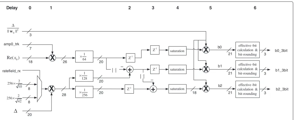
Figure 2Soft-bit calculation procedure in the soft demapper.
trade-off between complexity and performance. Note that at high signal-to-noise ratio (SNR) region, Eq. (10) is a piecewise linear function of real or imaginary part of
ZF equalized outputx, as suggested in [8]. Furthermore,ˆ
much simpler bit metric algorithm is suggested by [9] where complexity of the demapper is maintained at almost the same level for all the multi-level modulation modes.
Noise power weighting-based bit metric
As ZF MIMO detector disregards the noise enhancement effect, the boosted colored noise term is considered dur-ing generation of soft-bit information at the demapper. In Eq. (5), we see that the covariance matrix of noise vector
nis affected by ZF filter matrixW. In Eq. (5), the
vari-anceσ2of nulling vector and noise vector product can be
expressed as
Thus, by multiplying the inverse of norm of the ZF
fil-ter coefficient 1/WHi 2to the estimated symbolxˆi, the
exact variance of colored noise affected to soft-bit infor-mation is reflected on the channel decoder, delivering enhanced channel decoding performance.
Soft-bit weighting is especially crucial for coded multi-carrier OFDM systems, since colored noise boosted sub-carriers suffer low signal-to-interference noise ratio. Since colored noise is always present for all possible cases unless
SNR approaches infinity, an estimated symbol having
smallWHi 2value (i.e., high SNR) can be said to be more
reliable than those with highWHi 2values. Note thati
refers toi-th row vector here. Then, the simplified noise
power weight soft-bit LLR metric related to real part in case of 64-QAM modulation is defined as
b0
Since xˆi and ||Wi||2 are both scaled, soft-bit weighting
of noise enhancement should be /||Wi||2 instead of
1/||Wi||2, and their scaling effect is effectively gone. In
summary, only one division operation is necessary to
nor-malize the estimated transmit signal xˆi. In addition, we
found that the ratio of/||Wi||2is typically in the range
Table 1 List of variables used in the analysis
Channel determinant 11 bits
ampx_trk Scale for amplitude tracking 7 bits
ratefield_rx Modulation order indicator 1 bit
ˆ
MSB == 1 ? -3 : +3
+
b0=
wgt_max_dmp (saturate MSB 12/11/10/9 bits)
b0_3bit =
wgt_max_dmp (remove LSB 7/8/9/10 bits)
Absolute value greater
than/equal to 3 ?
no yes
Figure 3Effective 3-bit extraction process.
of 0 to 8. Therefore, only 3 bits are enough to express the colored noise weighting as well as normalization factor.
Hardware architecture
The hardware architecture of soft demapper is designed such that they are consisted of two functional parts, as illustrated in Figure 2. First half block, during clock delay
intervals 1 to 5, is designated for calculating exact soft-bit values, and the other half, at delay 6, is specialized for effective 3-bit extraction process.
Before MIMO detector output signals are processed, amplitude tracking value is multiplied to the scaled
esti-mated symbol xˆi in consideration of channel variation
over time,
¯
x0=amp0_trk· ˆx0,
¯
x1=amp1_trk· ˆx1, (14)
where “ampi_trk" is amplitude tracking result of thei-th
spatial stream. This tracking coefficient reflects variation of average magnitude of pilot tones allocated to every data field OFDM symbols. Although time selectivity of wide-band nomadic systems such as wireless local area network (WLAN) is considered negligible, average channel power may change for long packet format in case of long packet aggregation feature is enabled.
After the multiplication of incoming ZF equalized signal
by amplitude tracking resultamp0_trk, 6 least significant
bits (LSBs) corresponding to floating point are cut off,
making scaled signalxˆ0
·amp0_trk as 20 bits.
Dur-ing that time, higher order modulation threshold values corresponding to decision boundary of 16-QAM and 64-QAM signals are calculated to let soft demapper extract sub-optimal LLR values. Note that these decision
bound-aries are scaled by.
As shown in Figure 2, “ratefield_rx" control signal is
the indication of the modulation order of incoming sym-bols. For OFDM-based IEEE 802.11 WLAN systems, this
Table 2 Simulation parameters
Carrier frequency 5 GHz
System bandwidth 20 MHz
Channel model Exp. 50-ns rms delay spread
Modulation & coding set MCS12 to MCS15
Packet length 1,000 bytes
Freq. / sampl. offset 40/40 ppm
signal is set to either 16-QAM or 64-QAM after the detec-tion of transmission rate indicated in the Legacy/HT sig-nal field. At processing delay time 4, clipping operation is performed since any multiplication size larger than 20 bits involves typically more than one built-in multiplier block in field programmable gate array (FPGA) implementation. Thus, saturation process is necessary to lower complexity. It takes the total of five clock time delays to acquire the
soft-bits. Finally, normalization factor/||Wi||2is
mul-tiplied, as indicated in Eq. (13), before the 3-bit extraction process (Table 1).
Three-bit extraction/quantization
Based on colored noise power weight bit metric discussed in the previous section, the soft-bit calculation procedure (Eq. 13) is a piecewise linear function [9] which is simple to implement. In contrast, the 3-bit quantization process, however, is a non-linear function. During the extraction, the magnitude of soft-bit values are analyzed for a given specific range.
The bit metric output signal, as shown in Figure 3, is first saturated to one of 9-, 10-, 11-, or 12-bit signal which length of saturation depends on register control
value “wgt_max_dmp". We can set this as a fixed value
since normalization resultsE[||ˆxi||2]=1 for BPSK signals.
Next, LSBs of the saturated signal are removed; the num-ber of LSBs depends on pre-determined register control value also. This is the effective-bit threshold adjustment technique. Consequently, what is left is LLR with three effective bits.
At this point, 3-bit LLR is examined whether its absolute value is greater than or equal to 3. If it holds true, the final 3-bit output is set to either 3 or -3, limiting 3-bit signed number to seven levels instead of eight (i.e., from -4 to 3). If not, bit-rounding scheme, equivalent to adding 0.5 bit, is applied to mitigate problems related to negative-value biased signal due to fixed-point quantization effect on 2’s compliment conversion. We later find that this biased sig-nal affects the soft-input Viterbi decoding performance
significantly, especially for high code rateR = 5/6. Note
that the above procedure can be applied similarly to
find-ing the 3-bit value of /||Wi||2. In this case, b0 of
Figure 3 can be replaced with| − ||Wi||2|,≥ ||Wi||2
or|− ||Wi||2|/4,< ||Wi||2since bothand||Wi||2 are positive values.
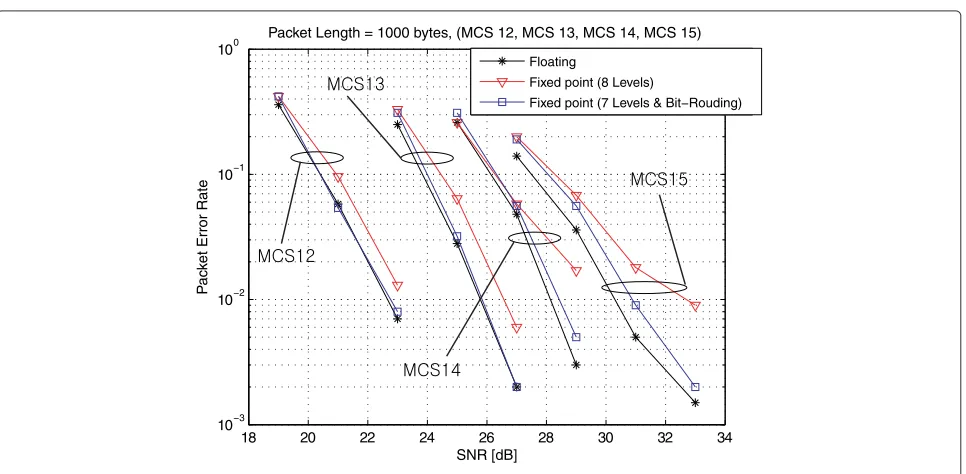
Simulation results
In this section, we present the fixed-point simulation results of implemented soft demapper applied to the IEEE
802.11n-based 2 × 3 MIMO-OFDM system. As
indi-cated earlier, all fixed-point simulation results are based
18 20 22 24 26 28 30 32 34
10−3 10−2 10−1 100
SNR [dB]
P
a
c
k
et Error Rate
Packet Length = 1000 bytes, (MCS 12, MCS 13, MCS 14, MCS 15)
Floating
Fixed point (8 Levels)
Fixed point (7 Levels & Bit−Rouding)
on Viterbi decoder with 3-bit LLR input. The simulation results are based on bit and cycle true synchronized clock-based C/RTL codes targeted for the IEEE 802.11n system implemented/verified with FPGA technology, as shown in Figure 4.
We apply exponentially decaying 50-ns root mean square (rms) delay spread channel model. The chan-nel sampling rate is adjusted to 80 Msps. All simulation cases have frequency/time offset of 40 ppm, introduced by TX/RX carrier frequency mismatch and TX/RX sam-pling mismatch from ADC converter, respectively. Also, RF impairments are included: RAPP power amplifier with 10-dB backoff and phase noise with a pole-zero model. All real system impairments mentioned above are compen-sated with AGC, carrier frequency offset compensation, time synchronization, and phase tracking algorithms. Channel estimation is done by capturing the frequency-domain tone-interleaved per transmit antenna version of long sequence preambles defined in [2] and saving them
asHin 3×2 matrix form in the MIMO detector.
Simu-lation parameters are given in Table 2, and packet size is fixed to 1,000 bytes, as suggested in [10].
As shown in Figure 5, the packet error rate (PER) of var-ious soft-demapping schemes are plotted as a function of average SNR per received antenna. Here, floating-point simulation means such that not only soft demapper but all arithmetic calculations including entire RX front-end are based on floating-point operation. Out of 16 MCS modes, four transmission rates are chosen for analyz-ing fixed-point effect of soft demapper in comparison to floating-point simulation results. From MCS 12 to 14, performance gap between floating point and fixed point due to quantization error is kept minimum with proposed effective 3-bit extraction soft demapper whereas conven-tional eight-level quantization scheme consistently has SNR loss about 0.5 dB. On top of this, PER error floor is observed in MCS 14 and 15. In contrast, error floor is suc-cessfully eliminated by applying proposed fixed-point soft demapper. The low-complexity soft demapper enables the MIMO-OFDM-based IEEE 802.11n WLAN system to achieve its peak data rate of 270 Mbps with packet error ratio of 1% at SNR 31 dB.
Conclusions
We have proposed a linear MIMO detector-based soft-demapping metric as well as its hardware architecture that is simple to implement. With a combining technique of limiting 3-bit effective quantization to seven-level bit-rounding and effective-bit threshold adjustment, a consid-erable gain can be realized in coded MIMO-OFDM-based system in high data rate transmission modes, especially for high code rates. The proposed soft-bit demapper has been tested/verified with Xilinx Virtex II XC2V8000 FPGAs operating at 80 MHz.
Competing interests
Both authors declare that they have no competing interests.
Acknowledgments
This research was funded by the MSIP (Ministry of Science, ICT & Future Planning), Korea in the ICT R&D Program 2013. The work of Hoojin Lee was financially supported by Hansung University. The content of this paper was partially presented in [11].
Author details
1Distributed Wireless Access Research Laboratory, ETRI, Daejeon 305-700,
South Korea.2Department of Information and Communications Engineering,
Hansung University, Seoul 136-792, South Korea.
Received: 11 March 2013 Accepted: 15 May 2013 Published: 29 May 2013
References
1. IEEE Standard 802.11a-1999, Part 11, Wireless LAN Medium Access Control (MAC) and Physical Layer (PHY) Specifications : High-speed Physical Layer in 5 GHz Band, IEEE (1999)
2. IEEE Standard 802.11n-2009, Part 11. Wireless LAN Medium Access Control (MAC) and Physical Layer (PHY) Specifications Amendment 5: Enhancements for Higher Throughput, IEEE (2009)
3. AV Zelst, inProc. of the 10th Mediterranean Electrotechnical Conference,
vol. 3. Space division multiplexing algorithms (Cyprus, 9–31 May 2000), pp. 1218–1221
4. H Yu, T Jeon, S Lee, inProc. of IEEE International Conference on Communications (ICC),vol. 4. Design of dual-band MIMO-OFDM system for next generation wireless LAN (IEEE Piscataway, 2005), pp. 2640–2644 5. PW Wolniansky, GJ Foschini, GD Golden, RA Valenzuela, inIEEE ISSSE ’98
V-BLAST: an arhitecture for realizing very high data rates over rich-scattering wireless channel (Pisa, 29 Sep–2 October 1998), pp. 295–300
6. H Artes, D Seethaler, F Hlawatsch, Efficient detection algorithms for MIMO channels: a geometrical approach to approximate ML detection. IEEE Trans. Signal Process.51(11), pp. 2808–2820 (2003) 7. SH Muller-Weinfurtner, Coding approaches for multiple antenna
transmission in fast fading and OFDM. IEEE Trans. Signal Process.
50(10), pp. 2442–2450 (2002)
8. R Pyndiah, Picart A, A Glavieux, inProc. of IEEE GLOBECOM ’95. Performance of block turbo coded 16-QAM and 64-QAM modulaitons (Singapore, 1995), pp. 1039–1043
9. F Tosato, P Bisaglia, inProc. IEEE International Conference on
Communications (ICC),vol. 2. Simplified soft-output demapper for binary interleaved COFDM with application to HIPERLAN/2 (IEEE Piscataway, 2002), pp. 664–668
10. AP Stephens, IEEE 802.11 TGn comparison criteria. IEEE 802.11 document, doc. no. 11-03-0814-31-000n (2004)
11. C Yoon, H Lee, inFuture Information Technology, Application, and Service, Lecture Notes in Electrical Engineering, Springer,vol. 164. Efficient soft-output demapping method for MIMO-OFDM WLAN systems (Springer Heidelberg, 2012), pp. 485–491
doi:10.1186/1687-1499-2013-143