R E V I E W
Open Access
Survey of hyperspectral image denoising
methods based on tensor decompositions
Tao Lin and Salah Bourennane
*Abstract
A hyperspectral image (HSI) is always modeled as a three-dimensional tensor, with the first two dimensions indicating the spatial domain and the third dimension indicating the spectral domain. The classical matrix-based denoising methods require to rearrange the tensor into a matrix, then filter noise in the column space, and finally rebuild the tensor. To avoid the rearranging and rebuilding steps, the tensor-based denoising methods can be used to process the HSI directly by employing multilinear algebra. This paper presents a survey on three newly proposed HSI denoising methods and shows their performances in reducing noise. The first method is the Multiway Wiener Filter (MWF), which is an extension of the Wiener filter to data tensors, based on the TUCKER3 decomposition. The second one is the PARAFAC filter, which removes noise by truncating the lower rankKof the PARAFAC decomposition. And the third one is the combination of multidimensional wavelet packet transform (MWPT) and MWF (MWPT-MWF), which models each coefficient set as a tensor and then filters each tensor by applying MWF. MWPT-MWF has been proposed to preserve rare signals in the denoising process, which cannot be preserved well by using the MWF or PARAFAC filters. A real-world HYDICE HSI data is used in the experiments to assess these three tensor-based denoising methods, and the performances of each method are analyzed in two aspects: signal-to-noise ratio and improvement of subsequent target detection results.
1 Review 1.1 Introduction
Hyperspectral images (HSI) attract more and more inter-est in recent years in different domains, such as geography, agriculture, and military [1-3]. They use the HSI to do the target detection [4] or classification [5] to find objects or materials of interest on the ground. Unfortunately, in the capturing procedure, the HSI is usually impaired by sev-eral types of noise, such as thermal noise [6], photonic noise [7], and strip noise [8]. Therefore, denoising meth-ods [9-13] have become a critical step for improving the subsequent target detection and classification in remote sensing imaging applications [14].
In HSI processing, images are modeled as a three-dimensional tensor, i.e., two spatial dimensions and one spectral dimension. The classical denoising methods [15-18] rearrange the HSI into a matrix whose columns contain the spectral signatures of all the pixels, then esti-mate the signal subspace by methods based on the analysis
*Correspondence: [email protected]
Institut Fresnel/CNRS-UMR 7249 Ecole Centrale Marseille, Aix-Marseille Université, Marseille 13013, France
of second-order statistics, and finally rebuild the original HSI structure after processing.
Since matrix-based techniques cannot take advantage of spectra in hyperspectral images, therefore, in order to treat the HSI as a whole entity, some new techniques were developed. For example, an HSI was treated as a hyper-cube in order to take into account the correlation among different bands [19,20], tensor-algebra was brought to jointly analyze the 3D HSI, etc. In this paper, we mainly focus on the problem of applying tensor algebra in reduc-ing noise in HSIs. Unlike the matrix-based denoisreduc-ing methods which are based on matrix algebra, the newly proposed tensor-based denosing methods utilize multilin-ear algebra to analyze the HSI tensor directly. It is well known that SVD (singular value decomposition) is impor-tant for matrix analysis. Similarly, there are two imporimpor-tant tensor decompositions: TUCKER3 and PARAFAC. These two decompositions play significant roles in analyzing tensors. Therefore, in this paper, we focus on compar-ative methods based on multilinear algebra for sake of coherence with the recently developed method which combines multidimensional wavelet packet transform and
TUCKER3 decomposition: The three methods involve a tensor decomposition either TUCKER3 or PARAFAC.
TUCKER3 decomposition, also known as lower rank-(K1,. . .,KN) tensor approximation (LRTA-(K1,. . .,KN)), has been firstly used as multimode PCA, which uses the first Kn PCA components in mode n, n = 1,. . .,N, to restore the multidimensional signal. The LRTA-(K1,. . .,KN)has been employed for seismic wave separation [21], face recognition [22], and color image denoising [23]. Although the LRTA-(K1,. . .,KN) can obtain good results in denoising, it is not an optimal solution for filtering noise in the aspect of the mean squared error (MSE). The multidimensional Wiener filter (MWF) has been proposed to overcome this drawback of LRTA-(K1,. . .,KN)[24]. MWF calculates the filter in each mode under the criterion of minimizing the MSE between the desired signal and the estimated signal, therefore it can been understood as an optimal LRTA-(K1,. . .,KN). Moreover, MWF can also be understood as an extension of the classical matrix-based Wiener filter to the tensor model by using multilinear algebra tools. MWF has been used in seismic wave denoising [24] and HSI denoising [12,25], and obtained good results. Recently, a statistical criteria has been adapted to estimate the rank of sig-nal subspace in each mode [13], which makes MWF an automatic method to reduce noise in the data.
Apart from TUCKER3, the PARAFAC [26] decomposi-tion, also known as CANDECOMP [27], is another way to decompose a tensor into lower rank factors. Distinguish-ing from TUCKER3, PARAFAC decomposes a tensor into a sum of rank-one tensors and only one rank K needs to be estimated for the tensor. Moreover, the PARAFAC decomposition is unique when the rankKis greater than one, whereas TUCKER3 cannot be. PARAFAC decom-position has recently been applied to chemical sciences [28], array processing [29], telecommunications [30], and HSI denoising [14]. As a comparison of MWF, refer-ence [31] shows the potential of PARAFAC in the HSI denoising. However, there is not an efficient way to estimate the rank of PARAFAC, which constrains it in automaticdenoising.
In a HSI, a rare signal is the one that is represented by only a few number of pixels, while the abundant sig-nal is the one that contains a large number of pixels compared to a rare signal [17]. MWF and PARAFAC treat a HSI as a whole entity in the denoising opera-tion; therefore, the abundant signals and the rare signals are processed together, which inhibits a drawback: the rare signals may be unintentionally removed. In fact, the energy of the rare signal is so weak compared to that of the abundant signal that the estimated signal sub-space cannot include the rare signal, and as a result, the rare signal is removed. MWPT-MWF (multidimen-sional wavelet packet transform (MWPT) with multiway
Wiener filter) has been proposed to overcome this draw-back of MWF and PARAFAC [32]. Instead of treating the HSI as a whole entity, MWPT-MWF firstly decom-poses the HSI into several coefficient sets, also called components, by employing MWPT, therefore the abun-dant signal and the rare signal can be separated. After this step, each component is filtered by MWF auto-matically. Because the rare signal and the abundant sig-nal are separated into different components, the sigsig-nal subspace in each component can be estimated more exactly.
The goal of this paper is to present a survey of the tensor-based denoising methods applied in filtering the HSI. Some recent simulations and comparative results on a real-world HYDICE HSI are also presented. The reminder of this paper is organized as follows: Section 1.2 briefly introduces some basic knowledge about multi-linear algebra. Section 1.3 introduces the signal model used in this paper. Sections 1.4, 1.5, and 1.6 present the recently proposed denoising methods MWF, PARAFAC, and MWPT-MWF, respectively. Section 1.7 supplies some comparative denoising and detection results. And finally, Section 2 concludes this paper.
1.2 Basics on tensor tools and multilinear algebra 1.2.1 Tensor model
A multiway signal is also called tensor. A tensor is a multi-dimensional array,X ∈RI1×I2×...×IN, in whichRindicates
the real mainfold, andNis the number of dimensions. The elements in this tensor can be expressed asxi1i2...iN, with
i1 = 1,. . .,I1; i2 = 1,. . .,I2;· · ·; iN = 1,. . .,IN. The n-th dimension of this tensor is calledn-mode. In partic-ular, tensorX is called a rank-one tensor when it can be written as the outer product ofNvectors [33]:
X =a1◦. . .◦aN, (1)
where◦indicates the outer product [34].
1.2.2 Multilinear algebra tools
n-mode unfolding Xn ∈ RIn×Mn denotes the n-mode unfolding matrix of a tensor X ∈ RI1×I2×...×IN, where
Mn = In+1. . .I1IN. . .In−1. The columns ofXn are the In-dimensional vectors obtained fromXby varying index inwhile keeping the other indices fixed. Here, we define then-mode rankKnas then-mode unfolding matrix rank, i.e.,Kn=rank(Xn).
n-mode product Then-mode product is defined as the product between a data tensorX ∈ RI1×I2×...×IN and a
matrix B ∈ RJ×In in mode n. This n-mode product is
denoted by
C=X×nB, (2)
ci1...in−1jin+1...iN 1.3 Problem formulation and signal modeling
A noisy HSI is modeled as a tensorR∈RI1×I2×I3resulting
from a pure HSIX ∈ RI1×I2×I3 impaired by an additive
noiseN ∈RI1×I2×I3. The tensorRcan be expressed as:
R=X+N. (4)
In this paper, we assume that the noiseN is zero-mean white Gaussian noise and independent from the signalX. The aim of this paper was to estimate the desired signalX from the noisy HSIR.
1.4 Multiway Wiener filtering 1.4.1 Denoising model
MWF provides an estimate Xˆ of the desired signal X from data tensorRby using a three-dimensional filtering, which can be expressed as follows [35]:
ˆ
X =R×1H1×2H2×3H3. (5)
From the signal processing point of view, the n-mode product is an-mode filtering ofR; therefore,Hnis named asn-mode filter.
In order to obtain the optimaln-mode filters{Hn, n= 1, 2, 3}, the usually used criterion is the mean squared error (MSE) between the estimated signal Xˆ and the desired signalX:
Then, the optimaln-mode filters are the ones which can minimize the MSE given in (6).
1.4.2 Calculation ofHn
To minimize the MSE given in (6) with respect ton-mode filters{Hn, n = 1, 2, 3}, the derivation is employed and the calculation details are presented in [24]. By setting the derivation of the MSE to zero, the expression of the optimaln-mode filterHnis [24]:
Hn=V(sn)(n)V(sn) T
, (7)
where V(sn) is a matrix containing the Kn orthonormal basis vectors of the signal subspace in the column space of then-mode unfolding matrixRn, and
(n)=diag However, in the practice, theIn−Knsmallest eigenvalues are generally different. Hence,σγ(n)2 can be estimated by:
ˆ
1.4.3 Estimation of Kn
Being used in the computation of then-mode filterHn, expression (7) requires the unknown Kn value, i.e., the number of largest eigenvalues of the covariance matrix of γRR(n), for n=1, 2, 3. Choosing a small Kn makes that some signals are lost whereas choosing a largeKnmakes that noise is included after restoration. For this case, the optimal Kn should be estimated to yield an optimum restoration. Akaike information criterion (AIC) is a crite-rion used to measure the information lost; therefore, it is employed in MWF to determine the optimal rankKn[13]. For moden, the AIC can be expressed as:
AIC(kn)= −2Mn ofknwhich minimizes AIC criterion.
1.4.4 ALS algorithm
modes. The steps of this algorithm can be summarized as presented here.
1. Input:Data tensorR 2. Initializationk=0:
X0=R⇐⇒H
n=IIn∀n=1, 2, 3. WhereIInis the
In×Inidentity matrix.
3. ALS loop:Repeat until convergence, that is, for example, whileXk+1−Xk> ε
4. Output:Estimated signal tensor ˆ
X =R×1Hkc
1 ×2Hk2c×3Hk3c, wherekcis the convergence iteration index.
As the calculation ofn-mode filterHnin step 33b uti-lizes the filters in other modes{Hi, 1≤i≤3andi=n}, it shows that the MWF considers the relationships between elements in all modes of the data set.
1.5 PARAFAC filtering 1.5.1 Denoising model
Since the decomposition by TUCKER3 model is not unique and needs to estimate the rankKnin each mode, another tensor decomposition model PARAFAC was recently introduced to reduce noise inR[14]. Different from TUCKER3 model, PARAFAC model can decompose a tensorRuniquely into a sum of rank-one tensors:
ˆ
whereNˆ is the decomposition error. Under the assump-tion that signal can be expressed by finite rank PARAFAC factorization, the estimateXˆ of the desired signalX can be expressed by the PARAFAC model:
ˆ betweenXˆandRshould be minimized:
e(A1,A2,A3)= R−I×1A1×2A2×3A32. (17)
Nonetheless, it is worth noting that the criterion of PARAFAC is the squared error between the estimateXˆ and the noisy HSI R, while that of MWF is the mean squared error between the estimate Xˆ and the desired signal X (see (6)). For a given rank K, minimizing (17) means removing as little signal as possible in the denoising process.
1.5.2 Calculation ofAn
To obtainAnin each mode, the error given in (17) should be minimized: into (18), we can obtain
An=arg min
An(ApAq)T−Rn2
. (20)
Obviously, the estimation ofAnneeds information ofAp andAq, which are not known. In this situation, an ALS algorithm should be employed to calculate the optimalAn.
1.5.3 PARAFAC ALS algorithm
To jointly estimate An, a ‘PARAFAC ALS’ algorithm is introduced and its steps are listed as follows:
1. Input: k is less than the maximum number of iteration,k←k+1and then go back to step 33a. Otherwise, break the loop.
4. Output:
1.5.4 Rank estimation
As described in Section 1.5.1, PARAFAC filtering is an algorithm which minimizese(A1,A2,A3)in (17) under a given rankK. In other words, it is assumed that the rankK is known in PARAFAC filtering. Unfortunately, the rankK is generally unknown in practice; therefore, an algorithm used to estimateKis presented in this section. The details are as follows:
1. Input:
Data tensorR 2. Initialization:
Seti=1. Set rank-searching-set K-SCOPE. 3. Loop:
(a) SetK=K-SCOPE[i].
(b) Do PARAFAC decomposition: R=K
k=1ak1◦ak2◦ak3+ ˆN.
(c) At n=1,2,3, calculate the covariance matrix
CnofNˆn, then-mode unfolding matrix ofNˆ. (d) If
(i) σdiag2 =
1/IniI=n1(ci,i−1/InIi=n1ci,i)2< δ1, whereci,iis the diagonal elements of
Cn.
(ii) | Cn2−iI=n1c2i,i|< δ2
these two conditions are satisfied for all n=1, 2, 3at the same time, break the loop.
MWF and PARAFAC treatRas an entire entity in the denoising process. This works well when there are only abundant signals or the rare signals can be neglected. However, in the situation where the rare signals cannot be neglected, such as the target detection, MWF and PARAFAC might remove rare signals in the denoising process.
MWPT-MWF has been proposed to preserve rare sig-nals in the denoising process and hence improve the denoising performance. In MWPT-MWF,X is estimated by minimizing MSE between the desired signalXand its estimateXˆ:
MSE=E ˆX−X2. (21)
Nevertheless, unlike MWF or PARAFAC, MWPT-MWF reduces noise by jointly filtering the wavelet packet
coefficient set. The details of MWPT-MWF will be described in the following subsections.
1.6.2 Multidimensional wavelet packet transform
The multidimensional wavelet packet transform (MWPT) can be written in tensor form as:
CR=R×1W
1×2W2×3W3 (22)
and the reconstruction can be written as:
R=CR×1WT
1 ×2WT2 ×3WT3, (23)
where Wn ∈ RIn×In,n = 1, 2, 3 indicate the wavelet packet transform matrices. When the transform level vec-tor is l =[l1,l2,l3]T, where ln ≥ 0 denotes the wavelet packet transform level in mode n, the coefficient tensor CR
l,m, which is also called a component in this paper, of scalem=[m1,m2,m3], where 0≤ mn ≤2lk −1, can be extracted by
CR
l,m=CR×1Em1×2Em2×3Em3 (24)
and the corresponding inverse process is
CR=
where the extraction operatorEmnis defined as
Emn =[01,IIn
zero matrix with size In
2ln ×
(2ln−1−m)In
2ln .
1.6.3 Multiway Wiener filter in multidimensional wavelet packet domain
After the MWPT, abundant and rare signals can be sep-arated into different components; therefore, the signal subspace of each component can be estimated more accu-rately than that of the entire dataset. Furthermore, a better estimation of the signal subspace can improve the per-formance of MWF in each component. However, the denoising criterion of MWPT-MWF is the minimization of the MSE betweenXandXˆbut not the component and its estimate; therefore, this subsection proves the ability of MWPT-MWF in minimizing the MSE betweenXandXˆ, which is defined in (21). By performing MWPT to tensor R,X andN in expression (4), we obtain
R×1W1×2W2×3W3
=(X +N)×1W1×2W2×3W3
The coefficient tensor of each part:
and the coefficient tensor of the estimateXˆ: ˆ
From Parseval’s theorem, the following expression can be obtained:
which means that minimizing the MSE betweenXand its estimateXˆ is equivalent to minimizing the MSE between CX
tiway Wiener filter aforementioned in Section 1.4. After estimatingCˆlX,mfor eachm, we obtainCˆXl by
concatenat-1.6.4 Best transform level and basis selection
In MWPT-MWF, several parameters should be deter-mined, as presented here.
1. Level of transform: the performance of the algorithm is affected by the level of transform, which depends on the size of tensorR. The maximum level can be calculated by
NLk = log2Ik −5,k=1, 2, 3, (36)
where·rounds a number upward to its nearest integer, and the constant 5 is subtracted from log2Ikto make sure there are enough elements in each mode so that the transform is meaningful. Then, the set of possible transform levels can be expressed as:
Lk= {0, 1,· · ·,NLk}, k=1, 2, 3, (37)
where{·}denotes a set.
2. Basis of transform: there are many wavelet bases designed for different cases. For the simplicity of expression, we define
W = {w1, w2,· · ·, wNW} (38)
to denote the set of possible wavelet bases, where NWis the number of wavelets in this set.
The best transform level and basis should minimize the MSE or risk Rc(X,Xˆ) = E
X− ˆX2[36], whose equivalent form for each component can be expressed as:
Rc(X,Xˆ)=
m
EClX,m− ˆClX,m2 (39)
Then, the best transform level and basis can be selected by
While selecting the optimal l,w depends onX which is generally unknown. To overcome this drawback, an alternative solution should be found. Denoting by
ˆ CX
l,m[d] the estimate of ClX,mat the d-th ALS loop
afore-mentioned in Section 1.4.4 and noticing that, when ˆCX
l,m[d]− ˆClX,m[d−1]2 is minimized,CˆlX,m CˆlX,m[d] is
the optimal estimate ofClX,mobtained by MWF, and at the
same time, EClX,m− ˆClX,m2is minimized according to Section 1.4.2. Therefore, (40) can be replaced by
l,w= arg min
1.6.5 Summary of the MWPT-MWF
The proposed algorithm, which is denoted by MWPT-MWF, can be summarized as presented here.
1. Input:
(d) Calculate the risk ˆ
Rc=
m ˆC
X
l,m[d]− ˆClX,m[d−1]2. IfRˆc reaches a fixed threshold, return the optimall1,l2,l3,wandCˆlX,m.
4. Output:ConcatenateCˆlX,mto obtainClXand perform inverse MWPT:Xˆ = ˆClX×1W1T×2W2T×3W3T.
1.7 Experimental results
In this section, we use a real-world high spatial resolution image acquired by HYperspectral Digital Imagery Collec-tion Experiment (HYDICE). The HYDICE image contains 65 rows, 100 columns, and 160 spectral bands, and is mod-eled as a 65×100×160 tensor in this paper. Six targets of interest are selected in the image as shown in the ground-truth map in Figure 1 and the corresponding mask is shown in Figure 2. The spectral signatures of these six tar-gets are presented in Figure 3. These six tartar-gets are chosen because they have different spectral signatures and sizes, so that the denoising and target detection performance on different target sizes can be evaluated.
White Gaussian noise is added into the HSI with signal-to-noise ratio (SNR) ranged from 15 to 30 dB (with a step of 5 dB) to reproduce different simulation scenarios. MWF, PARAFAC, and MWPT-MWF are used to reduce noise in the HSI. The rank-searching-set of PARAFAC is set as [51,101,151,201], and wavelet db3 is selected to do MWPT with transform levels [l1,l2,l3]=[1, 1, 0].
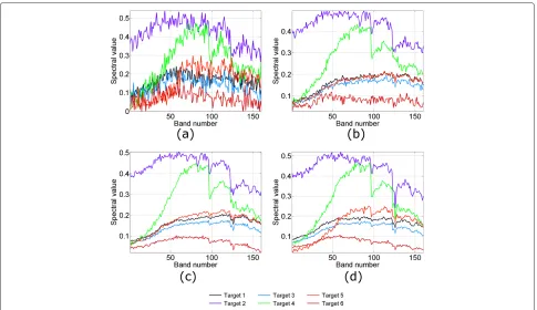
1.7.1 Denoising performance evaluation and comparison To present the denoising results intuitively, Figure 4 shows the target spectral signatures of the noisy HSI and the HSI denoised by MWF, PARAFAC, and MWPT-MWF, respec-tively. By comparing the four sub-figures in Figure 4, it is evident that denoising is a necessary procedure to restore the target spectral signatures. Moreover, we can see that there still exists more noise in Figure 4b than Figure 4c and Figure 4d. Especially, the spectral signatures of targets 1,
Figure 1Ground-truth map of real-world image HYDICE.
Figure 2Target mask of real-world image HYDICE.
3, and 5 are almost mixed together in Figure 4b. Figure 4c and Figure 4d are much better, at least the residual noise is small after denoising. However, the spectral signatures are changed more greatly after denoising by PARAFAC than by MWPT-MWF, which can be seen obviously from the signatures of targets 5 and 6. In Figure 4c, the signatures of targets 5 and 1 are almost overlapped, while in Figure 4d, these two signatures can be distinguished easily.
To compare the performances of MWF, PARAFAC, and MWPT-MWF, the SNR of the image after denoising, also named as SNR output, is defined as below [12]:
SNROUTPUT=10 log( X
2
ˆX−X2). (43) If SNROUTPUT is greater than SNRINPUT, we can con-clude that the algorithm improves the SNR of the image.
The SNROUTPUT values obtained when SNRINPUT is varying from 15 to 30 dB by different denoising methods are shown in Table 1. It is obvious that MWPT-MWF out-performs the other two denoising methods significantly. When the SNRINPUTis low, from 15 to 25 dB in Table 1, the denoising result of PARAFAC is better than that of
Figure 4Comparison of target spectra in (a) the noisy HSI and HSI denoised by (b) MWF, (c) PARAFAC, and (d) MWPT-MWF,
SNRINPUT=15dB.
MWF. But when the SNRINPUTis high, from 25 to 30 dB, the performance of MWF is slightly better than that of PARAFAC. Moreover, it is worth noting that all of these three methods can improve the SNR significantly. When the SNRINPUTis 15 dB, the SNROUTPUTafter denoising is 30 dB maximum by MWPT-MWF and 24 dB minimum by MWF. The denoising results shown in Table 1 give the experimental evidence of the benefits derived from the denoising procedure.
1.7.2 Target detection performance evaluation and comparison
In the last subsection, we have compared the denois-ing performances of different methods in the aspect of SNROUTPUT. However, sometimes SNROUTPUT cannot reflect the denoising performance we want, especially
Table 1 SNROUTPUTvs. SNRINPUTobtained after denoising
by methods MWF, PARAFAC, and MWPT-MWF
SNROUTPUT(dB)
SNRINPUT(dB) MWF PARAFAC MWPT-MWF
15 23.55 28.80 30.27
20 29.68 32.04 33.58
25 35.54 35.19 36.60
30 38.35 38.07 39.19
when we consider preserving small targets in the HSI while removing noise. Hence, in this subsection, we compare the target detection performance after denoising by MWF, PARAFAC, and MWPT-MWF.
Spectral Angle Mapper (SAM) detector [37] is used in the experiment to detect targets in the HSI. As SAM does not require the characterization of the background, it can avoid the inaccuracy of the comparison result caused by the noise covariance matrix estimation error. The SAM detector can be expressed as
TSAM(x)=
sTx
(sTs)1/2(xTx)1/2, (44)
where s is the reference spectrum and x is the pixel spectrum.
To assess the performances of detection, the probability of detection (Pd) is defined as
Pd=
ns i Nird
ns i Ni
(45)
and the probability of false alarm (Pfa) is defined as
Pfa=
ns i N
fd i
ns
i (I1×I2−Ni)
Figure 5Detection result obtained after denoising by MWF with parameters Pfa=10−4andSNRINPUT=15dB.
where ns is the number of spectral signatures, Ni the number of pixels with spectral signaturei,Nirdthe num-ber of correctly detected pixels, and Nifd the number of false-alarm pixels.
Figures 5, 6, and 7 are the target detection results after denoising by MWF, PARAFAC, and MWPT-MWF, respectively, in the noise environment SNRINPUT=15dB. In the images, the black pixel indicates no-target, the green the correct-detection, the red the false alarm, and the blue the missed target. From Figure 5, which shows the detection result after denoising by MWF, we can see that all of the three small targets (targets 1, 3, and 5) are missed in the detection. Moreover, most of the pix-els of target 5 are also missed. The detection result after denoising by PARAFAC, in Figure 6, is slightly better than that by MWF, but all of the small targets are also lost in the detection. MWPT-MWF shows its capability of preserving small targets in Figure 7, in which two of the three small targets are detected correctly. Apart from preserving small targets, MWPT-MWF can also improve
Figure 6Detection result obtained after denoising by PARAFAC with parameters Pfa=10−4andSNR
INPUT=15dB.
Figure 7Detection result obtained after denoising by MWPT-MWF with parameters Pfa=10−4andSNRINPUT=15dB.
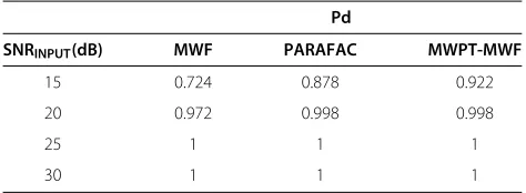
the detection performance of the large-size-small-energy target 6, which is obvious by comparing Figures 5, 6, and 7. To evaluate the detection performance in different noise environments, Table 2 shows the Pd values versus SNRINPUTof different denoising methods with SNRINPUT ranged from 15 to 30 dB.
It is obvious that the detection result after denoising by MWPT-MWF outperforms the two other methods. By comparing Table 2 with Table 1, we can understand that the denoising process can improve the target detection performance.
2 Conclusion
In this paper, a survey has been presented on three recently proposed tensor filtering methods: MWF, PARAFAC, and MWPT-MWF. They utilize multilinear algebra in analyzing a multidimensional data cube to jointly filter it in each mode.
The MWF extends the classical Wiener filter to the mul-tidimensional case by using the TUCKER3 decomposition while minimizing the MSE between the desired signal ten-sor and the estimated signal tenten-sor. As the filter in one mode relies on the filters in the other modes, the ALS algorithm is used to jointly calculate the MWF filters. In the filtering process, the signal subspace rank in moden needs to be known to remove the noise in the orthogonal
Table 2 SNRINPUTvs. Pd obtained after denoising by
methods MWF, PARAFAC, and MWPT-MWF
Pd
SNRINPUT(dB) MWF PARAFAC MWPT-MWF
15 0.724 0.878 0.922
20 0.972 0.998 0.998
25 1 1 1
complement subspace of the signal subspace. For this rea-son, the AIC algorithm is taken to estimate the rank in moden, which implies that the MWF can reduce noise automatically.
The PARAFAC filtering method was proposed to reduce the number of rank values to be estimated. As aforemen-tioned, the rank in each mode must be estimated in MWF, while only one rank must be estimated in PARAFAC fil-tering. Moreover, the low-rank PARAFAC decomposition is unique for rank values higher than one, whereas the TUCKER3 decomposition is not. However, there is not an efficient way to estimate the PARAFAC rank automat-ically. Though we have shown a rank estimation method in this paper, it is a time-consuming brute force searching way.
The MWF and PARAFAC were proposed to process the HSI as a whole entity, but this may remove the small tar-gets in an HSI in the denoising process. Distinguishing from MWF and PARAFAC, MWPT-MWF firstly trans-forms the HSI into different wavelet packet sets, also called components in this paper, and then filters each component as a whole entity. As the small targets are separated from the large ones, the former can be well preserved in the denoising process.
A real-world HYDICE HSI is used in the compara-tive study. Quantitacompara-tive and visual evaluation of the three methods is shown. From the experimental results, we can conclude that MWPT-MWF is a suitable tool for denoising especially when there exist small targets in the HSI.
Competing interests
The authors declare that they have no competing interests.
Acknowledgements
The authors would like to thank the reviewers for their careful reading and helpful comments which improve the quality of this paper.
Received: 16 August 2013 Accepted: 2 December 2013 Published: 17 December 2013
References
1. K Kotwal, S Chaudhuri, Visualization of hyperspectral images using bilateral filtering. IEEE Trans. Geosci. Remote Sens.
48(5), 2308–2316 (2010)
2. S Lewis, A Hudak, R Ottmar, P Robichaud, L Lentile, S Hood, J Cronan, P Morgan, Using hyperspectral imagery to estimate forest floor
consumption from wildfire in boreal forests of Alaska, USA. Int. J. Wildland Fire20(2), 255–271 (2011)
3. K Tiwari, M Arora, D Singh, An assessment of independent component analysis for detection of military targets from hyperspectral images. Int. J. Appl. Earth Obs. Geoinf.13(5), 730–740 (2011)
4. T Veracini, S Matteoli, M Diani, G Corsini, Nonparametric framework for detecting spectral anomalies in hyperspectral images. IEEE Geosci. Remote Sens. Lett.8(4), 666–670 (2011)
5. S Prasad, W Li, JE Fowler, LM Bruce, Information fusion in the redundant-wavelet-transform domain for noise-robust hyperspectral classification. IEEE Trans. Geosci. Remote Sens.
50(9), 3474–3486 (2012)
6. J Kerekes, J Baum, Full-spectrum spectral imaging system analytical model. IEEE Trans. Geosci. Remote Sens.43(3), 571–580 (2005)
7. ML Uss, B Vozel, VV Lukin, K Chehdi, Local signal-dependent noise variance estimation from hyperspectral textural images. IEEE J. Sel. Topics Signal Process.5(3), 469–486 (2011)
8. N Acito, M Diani, G Corsini, Subspace-based striping noise reduction in hyperspectral images. IEEE Trans. Geosci. Remote Sens.49(4), 1325–1342 (2011)
9. L Shao, R Yan, X Li, Y Liu, From heuristic optimization to dictionary learning: a review and comprehensive comparaison of image denoising algorithms. IEEE Trans. Cybernet. (2013) in press.
10. R Yan, L Shao, Y Liu, Nonlocal hierarchical dictionary learning using wavelets for image denoising. IEEE Trans. Image Process.
22(12), 4689–4698 (2013)
11. R Yan, L Shao, S Cvetkovi´c, J Klijn, Improved nonlocal means based on pre-classification and invariant block matching. J. Display Technol.
8(4), 212–218 (2012)
12. D Letexier, S Bourennane, Noise removal from hyperspectral images by multidimensional filtering. IEEE Trans. Geosci. Remote Sens.
46(7), 2061–2069 (2008)
13. N Renard, S Bourennane, Improvement of target detection methods by multiway filtering. IEEE Trans. Geosci. Remote Sens.46(8), 2407–2417 (2008)
14. X Liu, S Bourennane, C Fossati, Denoising of hyperspectral images using the PARAFAC model and statistical performance analysis. IEEE Trans. Geosci. Remote Sens.50(10), 3717–3724 (2012)
15. JA Richards,Remote sensing digital image analysis: an introduction (Springer, Berlin Heidelberg, 2012)
16. IC Chein, D Qian, Estimation of number of spectrally distinct signal sources in hyperspectral imagery. IEEE Trans. Geosci. Remote Sens.
42(3), 608–619 (2004)
17. O Kuybeda, D Malah, M Barzohar, Rank estimation and redundancy reduction of high-dimensional noisy signals with preservation of rare vectors. IEEE Trans. Signal Process.55(12), 5579–5592 (2007)
18. N Acito, M Diani, G Corsini, A new algorithm for robust estimation of the signal subspace in hyperspectral images in the presence of rare signal components. IEEE Trans. Geosci. Remote Sens.47(11), 3844–3856 (2009) 19. J Martin-Herrero, Anisotropic diffusion in the hypercube. IEEE Trans.
Geosci. Remote Sens.45(5), 1386–1398 (2007)
20. R Mendez-Rial, M Calvino-Cancela, J Martin-Herrero, Accurate implementation of anisotropic diffusion in the hypercube. IEEE Geosci. Remote Sens. Lett.7(4), 870–874 (2010)
21. N Le Bihan, G Ginolhac, Three-mode data set analysis using higher order subspace method: application to sonar and seismo-acoustic signal processing. Signal Process.84(5), 919–942 (2004)
22. MAO Vasilescu, D Terzopoulos, Multilinear image analysis for facial recognition, inInternational Association of Pattern Recognition (IAPR), vol. 2 (Quebec City, August 2002), pp. 511–514
23. D Muti, S Bourennane, Multidimensional signal processing using lower-rank tensor approximation, inIEEE ICASSP, vol. 3 (Hongkong, 6–10 April 2003), pp. 457–60
24. D Muti, S Bourennane, Multidimensional filtering based on a tensor approach. Signal Process.85(12), 2338–2353 (2005)
25. D Letexier, S Bourennane, J Talon, Nonorthogonal tensor matricization for hyperspectral image filtering. IEEE Geosci. Remote Sens. Lett.5, 3–7 (2008) 26. RA Harshman, ME Lundy, The PARAFAC model for three-way factor
analysis and multidimensional scaling, inResearch methods for multimode
data analysis(Praeger, New York, 1984), pp. 122–215
27. JD Carroll, JJ Chang, Analysis of individual differences in multidimensional scaling via an N-way generalization of Eckart-Young decomposition. Psychometrika35(3), 283–319 (1970)
28. A Smilde, R Bro, P Geladi,Multi-way analysis: applications in the chemical
sciences(Wiley, Hoboken, 2005)
29. X Guo, S Miron, D Brie, S Zhu, X Liao, A CANDECOMP/PARAFAC perspective on uniqueness of DOA estimation using a vector sensor array. IEEE Trans. Signal Process.59(7), 3475–3481 (2011)
30. AL De Almeida, G Favier, JCM Mota, PARAFAC-based unified tensor modeling for wireless communication systems with application to blind multiuser equalization. Signal Process.87(2), 337–351 (2007)
31. X Liu, S Bourennane, C Fossati, Nonwhite noise reduction in hyperspectral images. IEEE Geosci. Remote Sens. Lett.9(3), 368–372 (2012)
32. T Lin, S Bourennane, Hyperspectral image processing by jointly filtering wavelet component tensor. IEEE Trans. Geosci. Remote Sens.
33. TG Kolda, BW Bader, Tensor decompositions and applications. SIAM Rev.
51(3), 455–500 (2009)
34. A Cichocki, R Zdunek, A Phan, S Amari,Nonnegative matrix and tensor factorizations: applications to exploratory multi-way data analysis and blind
source separation(Wiley, Hoboken, 2009)
35. D Muti, S Bourennane, J Marot, Lower-rank tensor approximation and multiway, filtering. SIAM J. Matrix Anal. Appl.30(3), 1172–1204 (2008) 36. D Donoho, I Johnstone, Ideal denoising in an orthonormal basis chosen
from a library of bases. Comptes Rendus de l’Academie des Sciences-Serie I-Mathematique319(12), 1317–1322 (1994) 37. X Jin, S Paswaters, H Cline, A comparative study of target detection
algorithms for hyperspectral imagery, inSPIE Defense, Security, and Sensing (Orlando, FL, 13–17 April 2009)
doi:10.1186/1687-6180-2013-186
Cite this article as:Lin and Bourennane:Survey of hyperspectral image denoising methods based on tensor decompositions.EURASIP Journal on Advances in Signal Processing20132013:186.
Submit your manuscript to a
journal and benefi t from:
7Convenient online submission
7Rigorous peer review
7Immediate publication on acceptance
7Open access: articles freely available online
7High visibility within the fi eld
7Retaining the copyright to your article