R E S E A R C H
Open Access
Wireless MIMO switching: distributed
zero-forcing and MMSE relaying using network
coding
Miao Wang, Fanggang Wang
*and Zhangdui Zhong
Abstract
In a switching problem, a one-to-one mapping from the inputs to the outputs is conducted according to a switch pattern, i.e., a permutation matrix. In this paper, we investigate a wireless switching problem, in which a group of single-antenna relays acts together as a multiple-input-multiple-output (MIMO) switch to carry outdistributed precode-and-forward. All users transmit simultaneously to the MIMO switch in the uplink and then the MIMO switch precodes the received signals and broadcasts in the downlink. Ideally, each user could receive its desired signal from one other user with no or little interference from other users. Self-interference is allowed in the received signals, as it can be canceled when each user has the channel gain of its self-interference. We propose two distributed relaying schemes based on two widely adopted criteria, i.e., zero-forcing relaying and minimum mean square error (MMSE) relaying. For the distributed zero-forcing relaying, we further propose a message passing approach, with which the proposed zero-forcing relaying achieves significant throughput gain with little attendant overhead. We also claim that the proposed MMSE relaying achieves even larger throughput at the expense of larger amount of message passing. Simulation results validate the throughput gains of the proposed relaying schemes.
1 Introduction
Two-way relaying has attracted tremendous attention due to its potential of significantly improving the spectral effi-ciency [1-4]. By applying physical-layer network coding (PNC) [5], two half-duplex nodes can accomplish a bidi-rectional data exchange in two phases with the assist of a half-duplex relay.
Recently, much of the interest has been generalized to multi-way relaying [6-17]. The major challenge of design-ing a multi-way relaydesign-ing system lies in the co-channel interference induced by multiple users, which could dra-matically degrade the system performance if not handled properly. So far, most related works focus on two traf-fic patterns, i.e., pairwise data exchange where the users form pairs to exchange data within each pair, and full data exchange, where each user and full data exchange, where each user broadcasts to all other users [8-11]. In contrast, the traffic pattern studied in our earlier papers [12,13,16,17] is an arbitrary unicast, where the mapping
*Correspondence: [email protected]
State Key Laboratory of Rail Traffic Control and Safety, EIE, Beijing Jiaotong University, Beijing, China
from transmitters to receivers can be an arbitrary permu-tation and thus is more general. Such a framework is called wireless multiple-input-multiple-output (MIMO) switch-ing [12], and it is realized via a multi-antenna relay. In this paper, we follow the same framework and study the relaying schemes of the distributed relays.
Specifically, we investigate distributed relaying schemes for multiple single-antenna relays in the wireless MIMO switching network. Most of the existing works on multi-way relaying including our previous works exploited a multi-antenna relay to improve relaying efficiency [6,7,10-13,16,17]. However, due to limited size and power, etc., it is natural to deploy multiple single-antenna relays in the network. A group of such relays forms a MIMO switch where distributed beamforming is carried out. Since data exchange among the distributed relays is expensive, decode-and-forward schemes which involve joint coding and decoding at the relays are not practi-cal. Thus, non-regenerative relaying is used instead in the network. In addition, the precoding matrix at the relays is diagonal as each relay can only multiply its received
signal with a complex gain. The schemes for a multi-ple antenna relay fail for distributed relays. In [14], the authors proposed an orthogonalize-and-forward protocol to make multiple pairs of two-way transmissions inde-pendent with the aid of multiple single-antenna relays. In this paper, we propose a scheme to improve the sys-tem sum rate which chooses a precoding vector in the interference null space under the criterion of maximiz-ing the ratio of overall signal power to noise power. In [15], it was assumed that the users do not have knowl-edge of the channel state information. In order to achieve interference-free transmission at the users, the equivalent channel gains of each desired signal and its correspond-ing self-interference signal are designed to be equal to 1, and the gains of inter-user to 0 with proper precoding at the relays citemolisch11. We will show that by limited attendant message limited attendant message passing, the constraint that the channel gains of desired signals and self-interferences are equal can be relaxed. By doing so, the minimum required number of relays is reduced, we could achieve higher throughput. Furthermore, both cite-Bor07 and citemolisch11 assume that the [15] assume that the uplink and downlink channels are reciprocal. We will indicate that the relaying schemes in [14,15] fail for non-pairwise traffic pattern and solve this problem later in this paper.
As we know, zero-forcing schemes could boost noise at low signal-to-noise ratio (SNR) or for an ill-conditioned channel. Minimum mean square error (MMSE) schemes strike a balance between interference and noise. MMSE precoder and receiver were investigated in [18] for a single-hop transmission. Similar MMSE schemes with a multi-antenna relay were proposed to minimize sum mean square error (MSE) of all the users in [7,11] for multi-way relaying. In contrast, due to the practical issues aforementioned, we propose a distributed MMSE relay-ing scheme to circumvent the noise-elevatrelay-ing issue of zero-forcing schemes.
Specifically, in this paper, we first propose a distributed zero-forcing relaying scheme, which nulls all inter-user interferences and maximizes the ratio of overall signal power to noise power. For this relaying scheme, we also propose a message-passing approach with low overhead. After that, we propose a distributed MMSE relaying which minimizes the sum MSE and improves the throughput further by jointly optimizing the precoders at the relays and the receive filters at the users. We aim to deploy both relaying schemes for pairwise/non-pairwise switch-ing under reciprocal/nonreciprocal channels. For non-pairwise switching in reciprocal channels, a desired signal and the interference signal of its reverse link belong to the same signal space, which could make the proposed schemes fail. A trick by using the conjugate of the received signals at each hop is provided to deal with this problem.
Notation. The operators(·)T,(·)∗,(·)H, and(·)−1denote the transposition, the complex conjugation, the Hermi-tian and the inverse of a matrix, respectively.denotes the Hadamard product, i.e., element-by-element product. Tr{W}and rank(W)denote the trace and the rank ofW, respectively.E[·] is the expectation of a random variable.
W=diag{w}denotes a diagonal matrix with the elements ofwon the diagonal.w=diag{W}denotes a column vec-tor that contains the diagonal elements of the matrixW. [W]diagdenotes a diagonal matrix with the same diagonal
elements asW.
The remainder of this paper is organized as follows. The system setup of a distributed MIMO switching is introduced in Section 2. Two distributed relaying schemes based on zero-forcing and MMSE criteria are proposed in Sections 3 and 4, respectively. In Section 5, special cases of the two relaying schemes are further investigated in reciprocal channels. The simulation results are presented in Section 6. The paper is concluded in Section 7.
2 System model
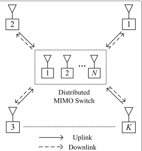
Consider a wireless MIMO switching network with K single-antenna users and N distributed single-antenna relay nodes which form a virtual MIMO switch as shown in Figure 1. The K users communicate with each other via the MIMO switch, assuming that direct links are not available between any two users. In this paper, we focus on a pure unicast traffic pattern where each user trans-mits to one other user only. We assume that each user and
relay is half-duplex, and then each transmission consists of two phases. In the uplink phase, all users transmit their signals simultaneously to the relays. After that, the relays broadcast their precoded signals back to the users in the downlink phase. independent and identically distributed (i.i.d.) noise fol-lowing a circularly symmetric complex Gaussian (CSCG) distribution, i.e., un ∼ CN(0,σ2). Upon receiving the uplink signal, each relay scales its received signal by a complex gain before forwarding to the users, that is,
z=Gy, (2)
where G = diag{g}, and the nth element of g is the complex gain factor at relayn.Gis designed to realize a particular switch pattern among the users, which is speci-fied by a mappingπ(·). That is to say, userisends data to userπ(i) through the relays in a transmission. The total transmission power of the relays is bounded byPR, i.e.,
E{Gy2} =Tr{G(HHH+γ2IN)GH} (3)
=gHg≤PR, (4)
where[HHH+γ2IN]diag. The received signals at the users can be written as
r=FGHx+FGu+w, (5)
wherew∈CK×1is the noise vector at the users, with i.i.d. noise samples following a CSCG distribution, i.e.,wk ∼
CN(0,σ2). Equivalently, the received signal of userπ(i)is
where the downlink channel is written as F =
(f1,· · ·,fK)T, andfk ∈ CN×1is the channel vector from the relays to userk. The first term of the right hand side of (6) is the desired signal; the second term is the self-interference which can be canceled by userπ(i)as long as the equivalent channel gainfTπ(i)Ghπ(i)is known to this user; the third term is the inter-user interference induced by other users; the last two terms are noises from the relays and the user end. Assuming that the upper- and
downlink phase both consume half of the total intervals, we obtain the sum rate as
R=1
In the following discussion, we optimize the sum rate based on two different criteria in the distributed MIMO switching network.
3 Distributed zero-forcing relaying
In this section, we propose a distributed zero-forcing relaying scheme that eliminates all interferences at the users. Specifically, we use a vector in the null space of the total inter-user interferences as the precoder. By prop-erly choosing the vector, we can maximize the ratio of the overall signal power to noise as well. In what follows, we elaborate the details of this scheme.
The total power of inter-user interference at userπ(i)is written as
To null the inter-user interference of user π(i), the precoder vectorgsatisfies
gTW∗π(i)g∗=0. (13)
Then, all inter-user interferences of the users being zero can be equivalently expressed as
gHWg=0, (14)
to guarantee each inter-user interference to be zero, i.e., N>K(K−2).
From (14), it is obvious that g is in the null space of
W. SinceWis the sum ofK(K−2)different interference subspaces, the rank ofWisK(K−2)with probability of 1. The orthonormal basis of the null space ofWdenoted as NW ∈ CN×(N−K(K−2)) here can be obtained by the
singular value decomposition:
W=SW NW
WVHW. (15)
The solution to (14) is thus a linear combination of the columns ofNWand can be written as
g=NWα, (16)
where α =[α1,· · ·,αN−K(K−2)]T is the linear combina-tion vector. We then determine the weightsαby maximiz-ing the ratio of the total power of the desired signals to the noise power. The total desired signal power is written as
Psig=E
of desired signal to the total noise powerηcan be obtained as
By inserting (15) into (4), the total power constraint at the relays can be rewritten as
gHg=αHNHWNWα (26)
=αHα≤PR, (27)
where = NHWNW. We claim that the relays need to
transmit with total power PR to maximize η. It can be
proved as follows: supposeαopt is the optimal combina-tion vector andαHoptαopt < PR, we can always find a
which contradicts with thatαoptis optimal. Thus, the
opti-malαsatisfies the equationαHPα
which is a generalized Rayleigh ratio problem [19]. The optimal α to maximize η is α = κα¯ where α¯ is the eigenvector of( )−1corresponding to its largest eigen-value, andκis a scaling factor to guarantee that the relays transmit with maximum power in (4), i.e.,
κ=
PR
¯
αHα¯. (32)
Remark 1.To perform self-interference cancelation, the equivalent channel response of self-interference
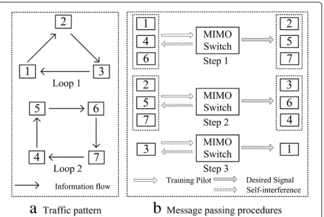
fTπ(i)Ghπ(i) in (6) is needed at user π(i). In addition, the equivalent channel response of desired signalfTπ(i)Ghi in (6) is also required at user π(i) to estimate the desired signal. We claim that the equivalent channel gains can be delivered within at most three steps for an arbitrary uni-cast pattern. We provide an example to show how the users get the required channel responses. Consider seven users with traffic demands as shown in Figure 2. If only
Figure 2An example of message passing.(a)Traffic pattern.(b)
useri(e.g., user 1 ) sends a training pilot to the relays and the relays broadcast the precoded signal back to the users, in such a transmission, useri(e.g., user 1) obtains the gain of its self-interference and userπ(i)(e.g., user 2 ) gets the channel gain of the desired signal link. Since zero-forcing relaying nulls inter-user interference completely, multiple users could send training pilots simultaneously without interfering each others, as long as usersi,π−1(i), andπ(i)
(e.g., users 1 , 3, and 2) do not transmit together. Based on this requirement, the users in a unicast cycle with even users can be scheduled in two steps, i.e., adjacent users are scheduled in different steps. The users in a uni-cast cycle with odd users can be scheduled in three steps. Note that the users from different cycles can be scheduled together because different cycles do not interfere with each other. As illustrated in Figure 2, the required chan-nel information needed can be obtained in three steps shown in Figure 2b for the switching pattern in Figure 2a. In the first transmission, users 1, 4, and 6 estimate the equivalent channel gains of self-interferences, and users 2, 5, and 7 estimate the gains of the desired signals. In the second transmission, users 2, 5, and 7 estimate the equivalent channel gains of self-interferences, and users 3, 4, and 6 estimate the gains of the desired signals. In the last transmission, user 3 estimates the equivalent channel gain of self-interference, and user 1 estimates the gain of its desired signal. Thus, we conclude that at most three steps are required for message passing before data transmission of the network.
Note that a central node is required to compute the precoding matrix at the relays following the assumption in [16,17]. In addition, channel informationHandFare required at the relays. The channel estimation at the relays is out of the scope of this paper. More details can be found in [20,21].
4 Distributed MMSE relaying
In this section, we propose a distributed MMSE relaying scheme that minimizes the sum MSE by jointly optimizing the precoder at each relay and the receive filter at each user end.
Similar to [13], we use a diagonal matrixBto express the weights of self-interference and a diagonal matrixC
to denote the receive filters. The receivers first filter the signal withCand then subtract the self-interferencesBx
from the filtered signalCr. The sum MSE can be written as
EPx−(Cr−Bx)2, wherePis aK-dimensional per-mutation matrix realizing the required switch pattern, i.e., the mapping defined byπ(·)as mentioned in Section 2; that is, columniofPis equal toeπ(i), i.e.,pi=eπ(i), where
eiis columniof an identity matrix. Together with the total transmission power constraint of the relays in (4), the sum MSE minimization problem is formulated as follows:
min
G,B,C E
(P+B)x−Cr2 (33a)
s.t. gHg≤PR, (33b)
B,C∈CK×K are diagonal. (33c)
Unfortunately, the optimization problem (33a) is non-convex and thus is generally difficult to solve in an optimal way. We then propose an iterative algorithm to optimize
G,B, andC. A similar method was used in [7,18], which considered a single-hop problem or a multi-way relaying without network coding. Here we show that PNC can be easily incorporated and optimized in the iterative method. To solve the problem (33), we introduce a cofactorβand define
¯
G=β−1G and C¯ =βC. (34)
The Lagrangian function is written as
L(g¯,B,C¯,λ)=E{(P+B)x−Cr2} +λ(gHg−PR)
(35)
=Tr{I+BBH−2{ ¯CFGH¯ (P+B)H} + ¯CFGHH¯ HG¯HFHC¯H
+γ2CF¯ G¯G¯HFHC¯H+σ2β−2C¯C¯H}
+λ(β2g¯Hg¯−PR), (36)
whereg¯ = diag{ ¯G} ∈ CN×1, and the last step follows by plugging (5) and (34).
4.1 Optimal(g¯,β)for fixed(B,C¯)
For fixed (B,C¯), the Lagrangian function (36) can be rewritten as
L(g¯,λ)=Tr{I+BBH+σ2β−2C¯C¯H}
−2{dHg¯} + ¯gHSg¯+λ(β2g¯Hg¯−PR),
(37)
where
d=diag{FHC¯H(P+B)HH} ∈CN×1, (38)
S=(FHC¯HCF¯ )(HHH+γ2IN)T∈CN×N. (39)
From the KKT conditions, we have
∂L(g¯,λ)
∂g¯∗ =0−→¯g=(S+λβ
2)−1d, (40)
∂L(g¯,λ)
∂λ =0−→β =
PR
¯
gHg¯, (41)
∂L(g¯,λ)
∂β =0−→λβ
4g¯Hg¯=σ2Tr{ ¯CC¯H}. (42)
Substituting (41) into (42), we get
λβ2= σ
2Tr{ ¯CC¯H}
PR
Plugging (43) to (40), we have
¯
g=
S+ σ
2Tr{ ¯CC¯H}
PR
−1
d. (44)
Note that similar KKT conditions were considered in [7]. However, the derivation provided here is much sim-pler.
4.2 Optimal(B,C¯)for fixed(g¯,β)
Denoteb = diag{B} ∈CK×1,c¯ = diag{ ¯C} ∈ CK×1. For fixed(g¯,β), i.e., fixedG, the Lagrangian function can be rewritten as
L(b,c¯)=K+bHb− ¯cHs− ¯cHQH1b−sHc¯−bHQ1c¯
+β−2c¯HQ2c¯+λ(β2g¯Hg¯−PR) (45)
=K+(Q3c¯−Q−31s)H(Q3c¯−Q−31s)−sHQ−32s
+(b−Q1c¯)H(b−Q1c¯)+λ(β2g¯Hg¯−PR),
(46)
where
s=diag{PHHG¯HFH} ∈CK×1, (47)
Q1=[FGH¯ ]diag∈CK×K, (48)
Q2=[FG¯(HHH+γ2I)G¯HFH+σ2β−2I]diag∈CK×K,
(49)
Q3=(Q2−QH1Q1)
1
2 ∈CK×K. (50)
From (45), we obtain the solution to minimize the sum MSE for fixed(g¯,β),
b=Q1Q−32s, (51)
¯
c=Q−32s. (52)
Note that from (51) the interference canceled at the user end is rewritten as
b=Q1c=diag(CFGH), (53)
which implies that self-interference is completely canceled by the solution ofBin (51).
By performing the above two steps iteratively, we present the proposed iterative approach as follows:
1: Init:B=B0,C¯ = ¯C0;
2: while the sum MSE can be reduced by more than
do
3: Calculateg¯andβusing (44) and (41), respectively;
4: CalculateBandC¯ using (51) and (52), respectively;
5: end while
4.3 Convergence of the iterative algorithm
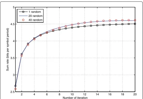
The sum MSE decreases monotonically in the iteration. Together with the fact that the sum MSE is nonnega-tive, we conclude that the iterative algorithm converges. Figure 3 shows the sum rate versus the number of iteration with different numbers of random initial vectors. When
2 4 6 8 10 12 14 16 18 20
2.5 3 3.5 4 4.5 5
Number of iteration
Sum rate (bits per symbol period)
1 random 20 random 40 random
Figure 3Convergence of the proposed iterative algorithm for MMSE relaying (SNR = 5 dB,N=N1,K=4).
multiple random initial vectors are used, we choose the vector that converges to the highest sum rate. It can be observed that the sum rate converges within 20 iterations. Higher sum rate can be achieved by setting various ran-dom initials, but the performance gain is marginal when the number of random initials exceeds 20.
Remark 2. With the proposed MMSE relaying, each user also demands the equivalent channel gains of the desired signal and the self-interference to recover the desired signal, as that for the proposed zero-forcing relaying men-tioned previously in Remark 1. However, each user needs to send its pilot individually in different steps, since there is residual inter-user interference at the users for the MMSE relaying. Larger overheads are required compared to the proposed zero-forcing scheme. In the simulations, we will show that with the larger overhead, the MMSE relaying can further improve the sum rate that achieved by the proposed zero-forcing scheme.
Remark 3.Here we compare the computational com-plexity of our schemes with the existing schemes in [14, 15]. We count the numbers of matrix inversion and singu-lar value decomposition (SVD) needed in each scheme as the complexity of other operations can be neglected com-pared to them. In the scheme proposed in [14], the major operation is an SVD operation of aN×K(K−2) inter-ference matrix with complexityO(NK2(K−2)2). For the scheme in [15], the major operations are the SVD of a N ×K(K−2)matrix and a matrix inverse operation of two N × N matrices. The computational complexity is
O(NK2(K−2)2)+O(2N3). In our proposed zero-forcing scheme, to get the weighting vector (15) at the relays, we need to computeNWandα. Specifically, we need to
getα, we need to compute the inverse of aN×Nmatrix and the eigenvector of aN×Nmatrix. The computational complexity isO(NK2(K −2)2)+O(2N3). With MMSE
relaying, we need to compute the inverse matrix of aN×N matrix to obtain (g¯,β) for fixed (B,C¯) and the matrix inverse of aK×Kmatrix to obtain(B,C¯)for fixed(g¯,β)in each iterative step. SupposeM(Mis less than 20 as evalu-ated in Figure 3) iterations are needed. The computational complexity isO(MN3)+O(MK3).
5 Further discussion in reciprocal channels We consider the case that the uplink channel and down-link channel are reciprocal, i.e.,F=HT, which is a widely adopted assumption for time-division duplex systems. In this case, the equivalent channel from userito userjis exactly the same as that from userjto useri. In what fol-lows, we investigate whether the proposed schemes can be used as well in the case of channel reciprocity.
5.1 Distributed zero-forcing relaying
We notice that for reciprocal channels, the situations for pairwise and non-pairwise traffic patterns are different as will be elaborated later in this subsection. We first refer to pairwise switching.
5.1.1 Pairwise switching
Recall that there are K(K − 2) independent inter-user interferences in nonreciprocal channels. Due to channel reciprocity, the interference from user i to user j, j =
π(i)(its equivalent channel ishTj Ghi) and that from user
j to user i (its equivalent channel is hTiGhj) belongs to the same space spanned by the equivalent channel vector
hihj. With this result, the number of relays required to null all inter-user interferences is larger than 12K(K−2), which is half of the required number for the nonreciprocal case.
5.1.2 Non-pairwise switching
For a non-pairwise switching, if the link from useri to userjis for a desired signal transmission, i.e.,j = π(i), then the reverse link from userjto useriis an interference link, i.e.,i=π(j)(or else it becomes a pairwise switching). In the case of channel reciprocity, the desired signal and the interference in its reverse link are in the same space
spanned by the equivalent channel vectorhihj. Thus, the interference can not be nulled by projection. We next pro-vide a trick here to differentiate the link from its reverse link.
In the downlink, the relays send the conjugate of the precoded signalzin (2) instead, i.e.,
z∗=G∗y∗=G∗H∗x∗+G∗u∗. (54)
At the user end, all users detectr, which is the conjugate of the received signals, i.e.,
r =HHGHx+HHGu+w∗. (55)
With this trick, the equivalent channel gain of the link from userito userjbecomeshHj Ghi, and its reverse chan-nel gain ishHi Ghj. Since the spaces spanned byhih∗j andh∗i hjare different, the problem becomes the same as the one for the nonreciprocal case and can be solved accordingly.
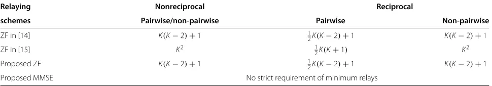
Remark 4.The minimum relays required in different cases are listed in Table 1. Recall the schemes in [14,15] that were proposed for multi-user two-way relaying, i.e., pairwise traffic pattern, assuming channel reciprocity. They can be directly extended to the case of channel non-reciprocity, while with different minimum required relays. However, the schemes in [14,15] cannot be extended to non-pairwise switching for reciprocal channels. The pro-posed conjugate trick could also heal the two propro-posed schemes.
5.2 Distributed MMSE relaying
For the MMSE scheme, the requirement of minimum relays is not necessary. However, for the non-pairwise switching with the assumption of channel reciprocity, even with sufficient relays, it is still difficult to improve the performance because the interferences and the desired signals are coupled together. The throughput can be boosted when the spaces of signal and interference are
Table 1 The minimum relays required for different relaying schemes
Relaying Nonreciprocal Reciprocal
schemes Pairwise/non-pairwise Pairwise Non-pairwise
ZF in [14] K(K−2)+1 12K(K−2)+1 K(K−2)+1
ZF in [15] K2 1
2K(K+1) K2
Proposed ZF K(K−2)+1 12K(K−2)+1 K(K−2)+1
completely decoupled with the trick of using conjugate, which will be shown later in Section 6.
6 Numerical results
In this section, we evaluate the sum MSE and the sum rates of the distributed MIMO switching network using different relaying schemes. Consider a pure unicast traffic pattern with four users, i.e.,K = 4. The maximum total transmission power of the relays is equal to the transmis-sion power of each user, i.e.,PR = 1. The noise levels at
each relay and user are the same. The entries of the chan-nel vectors are generated according toCN(0, 1)and all the results are obtained by averaging 10,000 Monte Carlo sim-ulations. In the simulation, we useN1andN2to denote the
required minimum relays for the proposed zero-forcing relaying and the scheme in [15], respectively. Note that the values ofN1andN2can be different in different cases as
shown in Table 1. Then, we present four observations as follows:
Observation 1.The proposed MMSE relaying scheme has better sum MSE performance than zero-forcing relay-ing schemes.
In Figure 4, we compare the sum MSE of our proposed schemes with the schemes in [14,15]. The simulations show that MMSE relaying outperforms the zero-forcing schemes significantly. With N1 relays, i.e., the minimum
required relays for the proposed zero-forcing scheme, the scheme in [15] fails with large sum MSE over the whole SNR region. The proposed zero-forcing scheme has the same sum MSE with the scheme in [14] asα is a scalar determined by the power constraint at the relays which is the same for both schemes withN1relays. With MMSE
0 5 10 15 20 25 30
10−2 10−1
100 101
102
103 104
SNR(dB)
Proposed MMSE Proposed ZF ZF in [14] ZF in [15]
sum MSE
Figure 4Sum MSE comparison of different relaying schemes (N=N1,K=4).
relaying, sum MSE is reduced significantly as the effect of noise is considered in the design of the scheme.
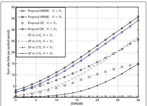
Observation 2.The proposed distributed zero-forcing and MMSE relaying schemes achieve significant through-put gain over the distributed schemes in [14,15].
In Figures 5, 6, and 7, we compare the sum rates of the two proposed approaches with the relaying schemes in [14,15] in different cases, i.e., Figure 5 for non-pairwise switching with nonreciprocal channels, Figure 6 for pair-wise switching with reciprocal channels, and Figure 7 for non-pairwise switching with reciprocal channels.b It is shown that roughly the same results can be obtained from the three different cases. Both the proposed schemes outperform the schemes in [14,15].
Specifically, from Table 1, we see that the proposed zero-forcing scheme needs less relays than the scheme in [15]. When usingN1relays, i.e., the minimum required relays
for the proposed zero-forcing scheme, the scheme in [15] fails without efficient throughput. When the number of relays increases toN2, i.e., the minimum required relays of
the scheme in [15], the proposed schemes still outperform this scheme significantly. Compared to the scheme in [14], the proposed zero-forcing scheme has the same through-put when usingN1yrelays. This is because withN1relays,
αis the same for both schemes as stated above. However, as the number of relays increases, the proposed zero-forcing scheme becomes better. The reason lies in that our scheme always optimizesαto maximize the ratio of over-all signal power to noise power. However, the scheme in [16] fails in this.
In all the cases, the proposed MMSE scheme achieves the best throughput performance, and it does not require
0 5 10 15 20 25 30
0 5 10 15 20 25 30 35 40
SNR(dB)
Sum rate (bits per symbol period)
Proposed MMSE, N=N1
Proposed MMSE, N=N2
Proposed ZF,N=N1
Proposed ZF,N=N2
ZF in [14],N=N1
ZF in [14],N=N2
ZF in [15],N=N1
ZF in [15],N=N2
Figure 5Sum rate comparison of different relaying schemes for non-pairwise switching in nonreciprocal channels
0 5 10 15 20 25 30 0
5 10 15 20 25 30 35 40
SNR(dB)
Sum rate (bits per symbol period)
Proposed MMSE, N=N1
Proposed MMSE, N=N2
Proposed ZF, N=N1
Proposed ZF, N=N2
ZF in [14],N=N1
ZF in [14],N=N2
ZF in [15],N=N1
ZF in [15],N=N2
Figure 6Sum rate comparison of different relaying schemes for pairwise switching in reciprocal channels
(N1=12K(K−2)+1,N2=12K(K+1),K=4).
minimum relays. The penalty is that its overhead is larger than the other schemes.
Observation 3.For reciprocal channels, the minimum required relays can be reduced to almost half of the other cases for pairwise switching, and the proposed conju-gate trick could avoid the failure of all the schemes for non-pairwise switching.
In Table 1, it can be observed that the number of relays required for pairwise switching in reciprocal channels is almost half of the other cases. The results in Figures 5, 6, and 7 further indicate that similar sum rate can be achieved in this case with almost half relays.
0 5 10 15 20 25 30
0 5 10 15 20 25 30 35 40
SNR(dB)
Sum rate (bits per symbol period)
Proposed MMSE, N=N1 Proposed MMSE, N=N2
Proposed ZF, N=N1
Proposed ZF, N=N2 ZF in [14],N=N1 ZF in [14],N=N2
ZF in [15],N=N1
ZF in [15],N=N2
Figure 7Sum rate comparison of different relaying schemes for non-pairwise switching in reciprocal channels
(N1=K(K−2)+1,N2=K2,K=4).
Figure 8 compares the performance of proposed MMSE relaying with conventional MMSE relaying not using con-jugate for non-pairwise switching in reciprocal channels. In this case, the sum rate of conventional MMSE relaying is quite low and can be improved trivially by increasing the number of relays, since the desired signals and some inter-ference signals belong to the same signal space. By using conjugate trick, the problem can be solved and the sum rate increases significantly.
Observation 4.The throughput performance improves as the number of relays increases, specially for the pro-posed zero-forcing relaying scheme with the number of relays fromN1toN1+1.
Figure 8 compares the performance of the proposed zero-forcing and MMSE relaying verse different number of relays. We take the non-pairwise switching in reciprocal channels as an example, as similar results can be obtained for other cases. Note that the performance of MMSE-based scheme degrades smoothly when N decreases, which makes this scheme also suitable for smaller system configurations. As for the zero-forcing relaying, one more relay boosts the performance compared to the case with minimum number of relays. However, the throughput improvement is limited whenNincreases.
7 Conclusion
In this paper, two relaying schemes are proposed for the distributed MIMO switching network. We indi-cate that the proposed distributed zero-forcing scheme exhibits large improvement of system throughput with limited attendant overhead compared to the existing dis-tributed zero-forcing schemes. The proposed disdis-tributed
0 5 10 15 20 25 30
0 5 10 15 20 25 30
SNR (dB)
Sum rate (bits per symbol period)
Proposed MMSE, N=N1+ 2 Proposed MMSE,N=N1+ 1
Proposed MMSE,N=N1
Proposed ZF,N=N1+ 2 Proposed ZF,N=N1+ 1
Proposed ZF,N=N1
MMSE w/o conj,N=N1+ 2 MMSE w/o conj,N=N1+ 1
MMSE w/o conj,N=N1
MMSE-based scheme can further improve the through-put performance over the proposed zero-forcing scheme at the cost of larger overhead. Both schemes can be applied to an arbitrary unicast pattern under recipro-cal/nonreciprocal channels, with the proposed conjugate trick healing the failure of non-pairwise switching with reciprocal channels.
We assume single-antenna users and relays and per-fect channel knowledge at the relays. Future research will focus on the distributed relaying schemes for multi-antenna nodes and with partial channel information at the relays.
Endnotes
a As for reciprocal channels, the number is different, which will be discussed later in Section 5.
b For nonreciprocal channels, the minimum required relays for pairwise and non-pairwise switching is exactly the same. In addition, similar results can be concluded from both pairwise and non-pairwise switching. Thus, we only show the simulation results of non-pairwise switching in Figure 5.
Competing interests
The authors declare that they have no competing interests.
Acknowledgements
This work was partially supported by the National Natural Science Foundation (no. 61201201 and U1261109), the State Key Lab of Rail Traffic Control and Safety (no. RCS2011ZT011), the Fundamental Research Funds for the Central Universities (nos. 2011JBM203, 2010RC007, and 2010JBZ008), and the Key Grant Project of Chinese Ministry of education (no. 313006).
Received: 14 June 2012 Accepted: 9 July 2013 Published: 24 July 2013
References
1. B Rankov, A Wittneben, inProceedings of the IEEE International Symposium on Information Theory(2006). Achievable rate regions for the two-way relay channel, Seattle, WA, 9–14 July (IEEE, Picataway, 2006), pp. 1668–1672
2. R Zhang, YC Liang, CC Chai, S Cui, Optimal beamforming for two-way multi-antenna relay channel with analogue network coding. IEEE J. Select. Area Commun.27(5), 699–712 (2009)
3. R Wang, M Tao, inProceedings of IEEE International Conference on Commununications (ICC). Joint source and relay precoding designs for MIMO two-way relay systems, Kyoto, 5–9 June (IEEE, Piscataway, 2011), pp. 1–5
4. T Yang, X Yuan, L Ping, IB Collings, J Yuan, A new physical-layer network coding scheme with eigen-direction alignment precoding for MIMO two-way relaying. IEEE Trans. Commun.61(3), 973–986 (2013) 5. S Zhang, SC Liew, PP Lam, inProceedings of the 12th Annual International
Conference on Mobile Computing and Networking. Hot topic: physical-layer network coding, Los Angeles, CA, 24–29 September (ACM, New York, 2006), pp. 358–365
6. Y Mohasseb, H Ghozlan, G Kramer, H El Gamal, inProceedings of the IEEE International Symposium on Information Theory,. The MIMO wireless switch: relaying can increase the multiplexing gain, Seoul, 28 June–3 July (IEEE, Piscataway, 2009), pp. 1448–1552
7. Joung J, Sayed A, Multiuser two-way amplify-and-forward relay processing and power control methods for beamforming systems. IEEE Trans. Signal Proc.58(3), 1833–1846 (2010)
8. D Gunduz, A Yener, A Goldsmith, HV Poor, inProceedings of the IEEE International Symposium on Information Theory,. The multi-way relay channel, Seoul, 28 June–3 July (IEEE, Piscataway, 2009), pp. 339–343 9. YE Sagduyu, D Guo, RA Berry, Throughput and stability for relay-assisted
wireless broadcast with network coding. IEEE J. Select. Area Commun.99, 1–11 (2012)
10. T Cui, T Ho, J Kliewer, inProceedings of the IEEE Global Telecommunications Conference. Space-time communication protocols for N-way relay networks, San Diego, November (IEEE, Piscataway, 2008), pp. 1–5 11. AUT Amah, A Klein, Beamforming-based physical layer network coding
for non-regenerative multi-way relaying. EURASIP J. Wireless Commun. Netw.2010(12) (2010)
12. F Wang, SC Liew, D Guo, in49th Annual Allerton Conference on Commununications, Control, and Computing (Allerton). Wireless MIMO switching with zero-forcing relaying, Monticello, IL, 28–30 September (2011), pp. 551–558
13. F Wang, SC Liew, D Guo, Wireless MIMO switching with zero-forcing relaying and network-coded relaying. IEEE J. Select. Area Commun.30(8), 1452–1463 (2012)
14. B Rankov, A Wittneben, Spectral efficient protocols for half-duplex fading relay channels. IEEE J. Select. Area Comm.25(2), 379–389 (2007) 15. C Wang, H Chen, Q Yin, A Feng, AF Molisch, Multi-user two-way relay
networks with distributed beamforming. IEEE Trans. Wireless Commun.
10(10), 3460–3471 (2011)
16. F Wang, X Yuan, SC Liew, D Guo, Wireless MIMO switching: weighted sum mean square error and sum rate optimization. IEEE Trans. Inform. Theory (2013). doi:10.1109/TIT.2013.2259893
17. F Wang, Wireless MIMO switching: network-coded MMSE relaying and user group selection. Trans. Emerging Telecommun. Tech. (2012). DOI10.1002/ett.2585
18. M Joham, W Utschick, J Nossek, Linear transmit processing in MIMO communications systems. IEEE Trans. Signal Proc.53(8), 2700–2712 (2005) 19. HV Trees, L Harry,Detection, Estimation, and Modulation Theory, Part IV :
Optimum Array Processing. (Wiley, Hoboken, 2002)
20. T Unger, Multiple-antenna two-hop relaying for bi-directional transmission in wireless communication systems, PhD Thesis, TU Darmstadt, 2009
21. H Degenhardt, F Hohmann, A Klein, inProceedings of IEEE International Symposium on Personal Indoor and Mobile Radio Commununications (PIMRC). Pilot transmission scheme and robust filter design for non-regenerative multi-pair two-way relaying, Sydney, 9–12 September (IEEE, Piscataway, 2012), pp. 2101–2106
doi:10.1186/1687-6180-2013-130
Cite this article as: Wanget al.:Wireless MIMO switching: distributed
zero-forcing and MMSE relaying using network coding.EURASIP Journal on
Advances in Signal Processing20132013:130.
Submit your manuscript to a
journal and benefi t from:
7Convenient online submission
7Rigorous peer review
7Immediate publication on acceptance
7Open access: articles freely available online
7High visibility within the fi eld
7Retaining the copyright to your article