Automatic Generation Control of a
Multi-Source Power System using FOPID Controller
by FA
Gurpreet Kaur1, Dr. Navneet Singh Bhangu2
P.G. Student, Department of Electrical Engineering, Guru Nanak Dev Engineering College, Punjab, India1
Assistant Professor, Department of Electrical Engineering, Guru Nanak Dev Engineering College, Punjab, India2
ABSTRACT: This paper focused on the automatic generaration control of multi-source power sytem comprising of hydro, thermal, gas units by using fopid controller. The fopid controller has good dynamics as compare to the io, pi, pid controller. Selection of parameters is done with firefly algorithm. The firefly algorithm is used for all of the three systems. Fopid controller controls the overshoot and oscillations of the respective system. The firefly algorithm is robust technique used for the optimization of the parameters
KEYWORDS: Automatic Generation Control, Fraction order controller, firefly algorithm, FOPID controller.
I. INTRODUCTION
In the power operation and protection, limiting the frequency and voltage in a nominal or predetermined value is one of the major issues that are being faced in this field. Generation power quality and reliability was expected to depend upon the determined balance between the power generated and demanded, combined with the power losses in the whole power system.
There is some deviation caused in power and frequency because of disruption in balance. Some random change in the loads can also be seen due to this disruption. This is the reason, it is recommended to use the proper control method so that overall constancy of power unit can be obtained. Till the time numerous control method exist and used to control the frequency parameter in different power system.
Automatic generation Control may be described as one of necessary controlling technique in interlinked power units to make sure that the operation is efficient and secure. If any variation among power production unit and power consumption unit has been identified then it will result in unwanted divergence in frequency
Automatic Generation Control is the best strategy to control the system to confirm the operation. If there is any mismatch occurs between generation and demand the frequency changes from its desired value. The primary goal of this strategy is to control the frequency and tieline power flow in interconnected area to its desired value. Therefore in order to achieve it many controllers are introduced in the system. These are integrator controllers, PI, PID, FOPID controllers. All have there own performance values but FOPID controller is the best among all because FOPID gives good dynamics response as compared PI, PID controllers.
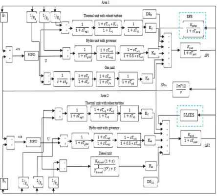
fractional order of differentiator. These knobs provide more flexibility for dynamics performance of the system. The multisource consists of the hydro, thermal, gas units.
There are many methods to solve the automatic generation problems. These methods includeparticle swarm optimization( pso),firefly algorithm(fa), genetic algorithm(ga),artificial bee colony(abc). Firefly algorithm is the new technique which is used in automatic generation control problems. The main advantage of FA is its robustness. It is the most efficient method than others to achieve the optimization values.
The three units are taken hydro, thermal and gas units. The advantage of gas units is its ability to turn on and off within minutes, supplying power during peak demand. FA is used for the selection of parameters that are present in supplementary controller.
II. FRACTIONAL CALCULAS
The fractional calculus definition’s and the Caputo’s definition can be differentiated and chosen is formulated as follow:
( ) =
( )∫
( )( )
( ) ……… (1)
The equation given above is the operator of the fractional differential where m in the equation shows the integer. In order to use the fractional operator in the study of application, it becomes necessary to give an approximation in the transfer of the integer order function.
= ∏ ……… (2)
=
. ( )
……… (3)
=
. ( )
……… (4)
= ∏ ……… (5)
Where μ in the equation shows the FO of derivative, P show count for zeros as well as poles, depicts the ith zero the range of
[ , ] whereas depicts pole in the range of [ , ] respectively.
III. FOPID CONTROLLER
The fractional order Controller can be better described with the use of an equation such as Fractional order differential equations. The Riemann-Liouville is the most commonly used definition of the fractional calculous i.e.
( ) Г( )( ) ∫
( )
( ) ( ) ……… (6)
In the above equationГ( − ) is the Euler’s gamma function. Alternatively, another definition for the fractional differentiation is
by the Grunwald Letnikov which is described as:
α ( ) → Г( ) ∑
Г( )
Г( )( )
( )
……….. (7)
After introducing the fractional order operator, the differentiator and the integrator i.e. D f(t)can be combined together. Another
important tool used is the Laplace transform which is the nth derivative of a signal represents such as:
Where x(t) is the signal relaxed at t=0. The equation 9 shows the normal Laplace transformation. Hence it has shown that fractional differential equation provides u(t) and y(t) signals relaxed at t=0. This term can be expressed as a transfer function form as:
G(s)= ⋯
⋯ ………. (9)
Where ( , ) ∈ , ( , )∈ ,∀( ∈ )
Among different PID controller, the is the most commonly used controller where an integrator order λ and
differentiator order μ can be any real numbers. For the given PID controller, the transfer function usedis given as:
( ) = + + , , > 0………. (10)
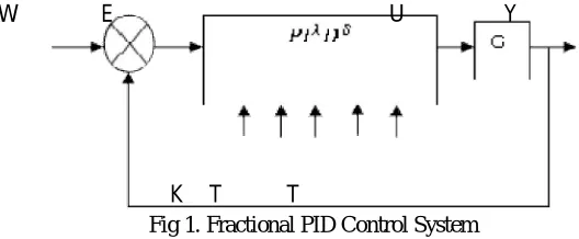
The PID controller with integrator and differentiator is also considered as the Fractional Order PID controller. In this type of controller the integral (δ) and derivative (λ) can be adjusted through the user in addition to the PID constants. The values of λ and δ vary between 0 to 1.By providing these extra knobs i.e. order of differentiation and Order of integration, the level of freedom for the operator is high.
Fig 1. Fractional PID Control System
Moreover, this factor also enhances the flexibility and opportunity to the operator in order to control the system by adjusting the dynamical properties. The fractional order controller is robust but produces significant output in the presence of non-linear actuator.
Fig 2.FOPID controller structure
E
W U Y
K T λ T
KP
KI
KD
Figure 3 explains the basic structure of the FOPID controller where three inputs have been forwarded to the system i.e. proportional, Integral and Derivative.
IV. TWO AREA POWER SYSTEM
PARAMETERS VALUES:
Table 1. Value of SSO algorithm parameters for LFC problem
Parameters Value
Population size Iteration Female Percent Male percent
Upper limit of Kr Kt and Ko
Lower limit of Kr Kt and Ko
Upper limit of Ksmes
Lower limit of Ksmes
Upper Limit of λ and µ Lower Limit of λ and µ
Upper limit of T1 T2 T3 T4 and Tsmss
Lower limit of T1 T2 T3 T4 and Tsmss
50 50 44 6 +10 -10 2 0 1 0 1 0
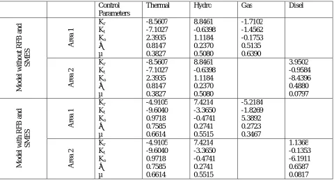
Table 2. Value of optimized FOPID controller parameters using SSO algorithm
Control Parameters
Thermal Hydro Gas Disel
Table 3. Value of SMES parameters optimized by SSO algorithm
Parameters Values
KS T1 T2 T3 T4 Ts 1.9059 0.6596 0.5762 0.1250 0.2931 0.5194
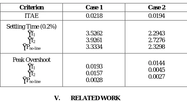
Table 4. Value of ITAE and settling time and peak overshoot without RFB and SMES
Criterion Case 1 Case 2
ITAE 0.0218 0.0194
Settling Time (0.2%) ∆f1
∆f2
∆Pno-line
3.5262 3.9261 3.3334 2.2943 2.7276 2.3298 Peak Overshoot ∆f1
∆f2
∆Pno-line
0.0193 0.0157 0.0028 0.0144 0.0045 0.0027
V. RELATED WORK
The proposed system develops and FOPID system which is based on firefly algorithm. Two benefits are associated with the FA technique as compare with different algorithm: capability to work with multimodality and ability to automatically divide itself into sub group. In the beginning, FA technique is totally dependent on lure and pleasant appearance reduces with length. From this it can be understood that the complete population will automatically divide itself into different small groups and all the groups can group about the local optimum. The optimum solution can be determined from different modes. After all this, sub groups permits the fireflies to determine all local optima at the same point of time when the size of population is adequately elevated as compare to count for different modes. The
average distance among fireflies can be monitored by 1
√ . Hence, the complete population can be divided into small
groups. Consider a situation where = 0, then the complete population will not able to divide itself into subgroups. The capability to automatically divide itself into subgroups makes it appropriate for extremely non linear systems, to resolve the multimodal optimization relates issues.
i. FIREFLY PARADIGM
interact or communicate with each other. Consequently, firefly algorithm is based on two concepts, first is changes in the intensity of light and formulation of pleasant appearance whereas attractiveness of firefly can be firmed with brightness exhibit by firefly. And it has treated as an intent function for problems related to optimization. As the attractng feature of firefly is directly propositional to the intensity of light.
The attractiveness of a firefly
can be describe in mathematical form as follow:
( ) = … … … . (11)
Here β defines the pleasant appearance at r=0 and β depict the coefficient for absorption of light at the source.
Distance between two fireflies
, = − = ∑ ( , − , ) ……….. (12)
, Has evaluated in eq. 3 which is a Cartesian length among any two differet fireflies i at xi and j at xj. Here xi and xj
depicts the spatial coordinates of the fireflies i and j respectively.This movement of a firefly me, attracted to firefly j can be evaluated.
Movement of a Firefly
= + ( − ) + (rand - )……….. (13)
Here 2nd term in the equation depicts attraction and third term named as Rand is the randomization in which numbers
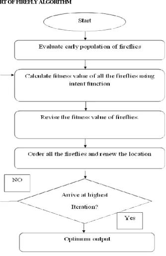
ii. FLOW CHART OF FIREFLY ALGORITHM
VI. EXPERIMENTAL RESULTS
The three units hydro, gas, thermal are controlled differently. The firefly algorithm is applied differently on every unit.
i.
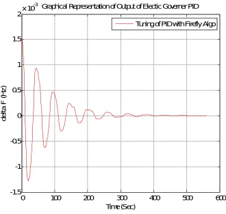
ELECTRIC GOVERNOR PID CONTROLLER:Initially the experiments have performed on the electric governor PID controller using the Firefly optimization algorithm.The acquired results have shown below:
Fig. 5. Output of the electric governor PID controller by using firefly Algorithm
The graph shows the output of the electric governor PID controller by using the firefly algorithm. The graph makes it clear that the output curve has fewer fluctuations and initially it is in negative frequency but then started growing towards the positive frequency.
0 100 200 300 400 500 600
-1.5 -1 -0.5 0 0.5 1 1.5
2x 10
-3 Graphical Representation of Output of Electic Governer PID
Time (Sec)
d
e
lt
a
F
(
H
z
)
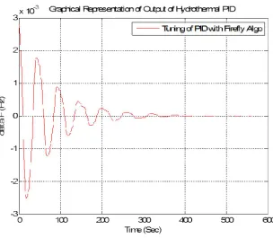
ii. HYDROTHERMAL PID CONTROLLER
Fig 6. Output of the Hydrothermal PID controller by using firefly Algorithm
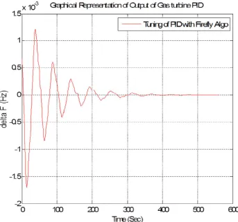
GASTHERMAL PID CONTROLLER
Fig 7Output of the Gas Turbine PID controller by using firefly Algorithm
The graph depicts the performance of the firefly algorithm which is showed in the form of output curve of the gas turbine PID controller tuned with firefly algorithm. The graph shows that there are less variations in the system using firefly algorithm.
VI. CONCLUSION
REFERENCES
1. Abdul-ghaffar I.H.,Ebrahim. A. E. and Azzam A., “Design of PID Controller for Power System Stabilization Using Hybrid Particle Swarm-Bacteria Foraging Optimization” WSEAS transactions on power systems, Issue 1, Volume 8, Pp 12-23, ,January 2013.
2. Arzani Ali, Arunagirinathan Paranietharan, Jayawardene, Iroshani and Venayagamoorthy, K.Ganesh,“Dynamic Performance Enhancement of a Utility-Scale Solar PV Plant”, IEEE, pp. 26 – 30, 2016.
3. Bevrani Hassan,Daneshfar Fatemeh and HiyamaTakashi, “A New Intelligent Agent-Based AGC Design With Real-Time Application”, IEEE, vol. 42, pp. 994 – 1002, 2012.
4. DebbarmaSanjoySaikia ChandraLalit, SinhaNidul, Kar Biswajit andDattaAsim, “Fractional order two degree of freedom control for AGC of an interconnected multi-source power system”, IEEE, pp.505–510, 2016.
5. Debnath Kumar Manoj,Singh Bahadur Manjit and Mallick KumarRanjan, “Design of Optimal 2-DOF PID controller using GWO Technique for Automatic Generation control of a multisource Power System”, IEEE, pp. 531 – 536, 2016.
6. El-Metwall A.Khaled, “Power system stabilization using swarm tuned fuzzy controller“ Proceedings of the 17th World Congress The International Federation of Automatic Control Seoul, Korea, July 6-11,Pp 11106-11111, 2008.
7. Guolian HOU,ZhengXiaobin, Jiang Pengcheng and Zhang Jianhua, “Study of Modeling and Intelligent Control on AGC System with Wind Power”, IEEE, pp. 4775 – 4780, 2014.
8. Hiyama Takashi, Zuo Dunding and Funabashi T., “Multi-Agent Based Automatic Generation Control of Isolated Stand Alone Power System”, IEEE, vol. 1, pp. 139 – 143, 2002.
9. Karray F.,Gueaieb W. and Sharhan Al-S., “The Hierarchical Expert Tuning of PID Controllers Using Tools of Soft Computing” IEEE , Vol. 32, no.Pp 77 -87., February 2002 .
10. Kawanishi Tetsuya,Inagaki Keizo, Kanno Atsushi and YamamotoNaokatsu, “Precise Measurement Techniques for Optical-to-electric Conversion”, IEEE, pp. 3906 – 3906, 2016.
11. Li Yuxiang, Zhao Yinliang and Shi Jiaqiang, “A Hybrid Samples Generation Approach in Speculative Multithreading”, IEEE, pp. 35 – 41, 2016.