Supervisors: Prof. Dr. Ir. C. H. Slump Ir. F. W. Hoeksema
Date: May 16, 2002
Report Code: SAS 016N02
University of Twente
Department of Electrical Engineering Laboratory of Signals & Systems
Enschede, The Netherlands University of Twente
Development of a Multiuser
Detection Testbed
Abstract
Contents
List of Figures vii
List of Tables ix
Preface xi
1 Introduction 1
1.1 Purpose and Constraints of Research . . . 2
1.2 Organization of this Thesis . . . 3
2 Code-Division Multiple Access 5 2.1 CDMA Principles . . . 5
2.2 Continuous-time CDMA Models . . . 8
2.2.1 Synchronous Channel . . . 8
2.2.2 Asynchronous Channel . . . 9
2.3 Discrete-time CDMA Models . . . 10
2.3.1 Synchronous Channel . . . 10
2.3.2 Asynchronous Channel . . . 12
3 Detection Techniques 15 3.1 Evaluation Criteria for Detection Techniques . . . 16
3.2 Conventional Detector . . . 18
3.3 Maximum Likelihood Sequence Estimator Detector . . . 21
3.4 Decorrelating Detector . . . 23
3.5 Minimum Mean Square Error Detector . . . 25
3.6 Successive Interference Cancellation Detector . . . 28
3.7 Parallel Interference Cancellation Detector . . . 30
3.8 Decorrelating Decision-Feedback Detector . . . 32
3.9 Comparison of Detection Techniques . . . 35
3.10 Conclusions . . . 43
4 Blind Adaptive MMSE and PIC Detector 45 4.1 Blind Adaptive MMSE Detector . . . 45
4.1.2 Minimizing Mean Output Energy . . . 47
4.1.3 Stochastic Gradient Decent Method . . . 49
4.1.4 Adaptive Implementation . . . 49
4.2 PIC Detector . . . 51
4.2.1 PIC Implementation . . . 53
4.2.2 Amplitude Estimation . . . 56
4.2.3 PIC Decision Rule Analysis . . . 57
4.3 Conclusions . . . 58
5 Simulation 61 5.1 Simulator . . . 61
5.1.1 Transmitter and Channel . . . 62
5.1.2 Detectors . . . 63
5.1.3 Simulation Modes . . . 63
5.1.4 Simulator Input and Output . . . 65
5.1.5 Implementation . . . 65
5.2 Simulation Results . . . 66
5.2.1 Conventional Detector . . . 66
5.2.2 Blind Adaptive MMSE Detector . . . 69
5.2.3 PIC Detector . . . 78
5.2.4 Detector Comparison . . . 83
5.3 Conclusions . . . 89
6 Blind Adaptive MMSE DSP Implementation 93 6.1 C6711 DSP Starter Kit . . . 94
6.2 Blind Adaptive MMSE Performance Test Implementation . . 94
6.3 ’C6711 Architecture . . . 95
6.4 Blind Adaptive MMSE Detector Optimization . . . 100
6.5 Detected Bits Per Second Performance . . . 106
6.6 Conclusions . . . 108
7 Conclusions and Recommendations 109 7.1 Conclusions . . . 109
7.2 Recommendations . . . 112
List of Figures
1.1 Basic CDMA receiver block diagram . . . 2
2.1 Direct-sequence spread-spectrum transmitter . . . 6
2.2 Direct-sequence spread-spectrum receiver . . . 6
2.3 Definition of asynchronous crosscorrelations (k < l) . . . 9
2.4 Bank of matched filters . . . 11
2.5 K-dimensional channel of matched filter outputs for asyn-chronous CDMA channel. . . 13
3.1 Classification of detection techniques. . . 16
3.2 Conventional detector. . . 18
3.3 MLSE detector. . . 21
3.4 Decorrelating detector. . . 23
3.5 MMSE detector. . . 25
3.6 SIC detector. . . 28
3.7 Two stage PIC detector . . . 31
3.8 Synchronous decorrelating decision-feedback detector. . . 33
3.9 Asynchronous decorrelating decision-feedback detector. . . 34
3.10 Capacity curves for perfect power control (Eb/N0= 8dB and processing gain = 31) [2] . . . 36
3.11 BER versus Eb/N0 with perfect power control (ten users and processing gain = 31) [2]. . . 37
3.12 Performance degradation in near-far channels (Eb/N0 = 5dB and processing gain = 31) [2]. . . 38
3.13 Asymptotic efficiency for a 2 user synchronous system with ρ= 0.6. . . 40
4.1 Blind Adaptive MMSE detector. . . 52
4.2 S stage narrowband PIC detector. . . 54
4.3 S stage wideband PIC detector. . . 55
5.1 BER/SNR plot conventional detector (ten users, processing gain = 31, perfect power control) . . . 67
5.2 BER/SNR plot conventional detector for two different sets of signature sequences (ten users, processing gain = 31, perfect power control) . . . 68 5.3 Convergence for 5 elements of the x sequence for varying
CDMA model parameters. Default parameters: µ = 10−4, 10 users, 10dB SNR, Perfect Power Control . . . 70 5.4 BER/I plot. Blind adaptive MMSE detector (µ= 10−4, ten
users, processing gain = 31, A interferers 20) . . . 72 5.5 BER/I plot. Blind adaptive MMSE detector (µ = 5·10−5,
ten users, processing gain = 31, A interfers 20) . . . 73 5.6 BER/SNR plot for ‘trained’ and ‘untrained’ blind adaptive
MMSE detector (µ = 10−4, ten users, processing gain = 31, perfect power control) . . . 76 5.7 BER/SNR plot. MMSE detector and blind adaptive MMSE
detector (µ = 10−4, ten users, processing gain = 31, perfect power control) . . . 78 5.8 BER/SNR plot. Narrowband / wideband PIC detector (ten
users, processing gain = 31, perfect power control) . . . 79 5.9 BER/SNR plot. 2-stage / 3-stage narrowband PIC detector
(ten users, processing gain = 31, perfect power control) . . . 80 5.10 BER/SNR plot. Full-cancellation / partial-cancellation
3-stage narrowband PIC detector (ten users, processing gain = 31, perfect power control) . . . 81 5.11 BER/SNR plot. Actual amplitudes / estimated amplitudes
3-stage partial cancellation narrowband PIC detector (ten users, processing gain = 31, perfect power control) . . . 82 5.12 BER/SNR detector comparison with perfect power control
(ten users, processing gain = 31) . . . 83 5.13 BER/SNR detector comparison with A interferers 20 (ten
users, processing gain = 31) . . . 85 5.14 Performance degradation in near-far channels detector
com-parison (three users, SNR = 5dB, processing gain = 31) . . . 86 5.15 User capacity detector comparison, (SNR = 8dB, processing
gain = 31, perfect power control) . . . 87 5.16 Simulation of transmission of an image (ten users, SNR =
List of Tables
3.1 Summary of requirements and computational complexity of multiuser detection techniques. . . 41 6.1 Overview of clock cycles and execution units for the
instruc-tions used by the blind adaptive MMSE detector algorithm. . 99 6.2 Clock cycles used by different parts of the blind adaptive
MMSE detector algorithm. . . 101 6.3 Clock cycles used by different parts of the optimized blind
adaptive MMSE detector algorithm. . . 103 6.4 Clock cycles used by different parts of the optimized blind
adaptive MMSE detector algorithm using double reads. . . . 104 6.5 Clock cycles used by the optimized blind adaptive MMSE
detector algorithm using double reads with unrolled first loop 106 6.6 Number of channels supported by a ’C6711 implementation
of the blind adaptive MMSE detector for often used data rates108
Preface
When I started thinking about a subject for my master’s assignment, the final assignment of my study electrical engineering at the University of Twente, I quickly knew that I would like to work on digital signal process-ing in cellular wireless mobile communications. While studyprocess-ing literature on cellular wireless mobile communications I became interested in multiuser de-tection techniques for code-division multiple access wireless communication systems. This thesis therefor describes the research on multiuser detection in cellular wireless mobile communications performed for my master’s assign-ment at the Laboratory of Signals & Systems of the Faculty of Electrical Engineering of the University of Twente.
The work described in this thesis would not have been realized without the help of many others. First of all, I wish to thank my supervisors Prof. Dr. Ir. Kees Slump and Ir. Fokke Hoeksema for providing guidance, support and helpful comments during my master’s assignment and for carefully reading this thesis. I would also like to thank Ing. Geert-Jan Laanstra for his help with getting the DSP to work. I wish to thank Hans Roelofs for his help on understanding the blind adaptive MMSE detector and for numerous discussions on multiuser detection. Further I would like to thank the staff and students of the Laboratory of Signals & Systems for providing such a nice working environment. Last but certainly not least, I wish to thank my family, friends and roommates for their support during my studies.
Enschede, May 16, 2002 Jordy Potman
Chapter 1
Introduction
Cellular wireless mobile telephony is an example ofmultiple access commu-nications. In multiple access communications several users share a common communications channel over which they can send information simultane-ously. Multiple access techniques are used to share the available channel resources with different users. In cellular wireless mobile telephony tra-ditionally Frequency-Division Multiple Access (FDMA) and Time-Division Multiple Access (TDMA) multiple access techniques have been used. In these techniques frequency bands, respectively time slots are allocated to a user. The frequency band or time slot of this user is disjoint from the frequency band or time slot of all the other users. In this way the multiple access channel reduces to a multiplicity of single point-to-point channels.
With the introduction of the IS-95 system in the United States and some other countries and the rise of 3rd generation cellular wireless mobile telephony a third multiple access technique,Code-Division Multiple Access
(CDMA), has gained importance. Instead of dividing the available channel resources over the different users by allocating frequency or time slots, this technique allocates all resources to all simultaneous users, controlling the power transmitted by each to the minimum required to maintain a given signal-to-noise ratio for the required level of performance. Each user employs a noiselike wideband signal occupying the entire frequency allocation for as long as it is needed. In this way, each user contributes to the interference affecting all the users, but to the least extent possible. The interference that a user experiences caused by the other users on a channel is called multiple access interference (MAI). The different users on a channel can be identified by the ‘signature’ of their noiselike wideband signal.
In the conventional method for detecting the information sent by a user in a CDMA system, multiple access interference is not taken into account. This method follows a single-user detection strategy in which each user is detected separately and the interference caused by the other users is treated as noise. Because of the nature of the multiple access interference, however,
Figure 1.1: Basic CDMA receiver block diagram
amultiuser detection method is a better strategy. Here, information about the other users is used to improve detection of each individual user.
Over the years there has been a lot of research on the development of
multiuser detection techniques. This has lead to a few optimal and a num-ber of suboptimal multiuser detection techniques. Until recently however, there has not been much effort in the practical implementation of these tech-niques. A way to study the practical implementation of multiuser detection techniques is the development of a test-bed. The test-bed provides the en-vironment in which these multiuser detection techniques would operate in a as practical system as possible and therefor allows development and testing of multiuser detection techniques in real world conditions.
1.1
Purpose and Constraints of Research
The purpose of research is todevelop a DSP-based multiuser detection test-bed that allows real-time evaluation of multiuser detection algorithms for CDMA systems. To make this project feasible considering the time-frame of a Master’s Thesis project and the available resources, a number of limitations is set on the test-bed.
The test-bed is limited to the baseband part of the CDMA receiver, after carrier-demodulation and before any error correction or other bit operations, see Figure 1.1. In the baseband part of the CDMA receiver the signals of the different users in the CDMA system are separated from each other. Therefor this is the part of a CDMA receiver that is of interest for multiuser detection. The test-bed uses a very simple multiuser additive white Gaussian noise channel model. Real-world wireless mobile communication channels are a lot more complicated and are not only noisy but also have multipath and fading properties.
In a practical CDMA receiver synchronization techniques are used to achieve synchronization with the received signal. In the test-bed, however, it is assumed that the required synchronization information is available to the receiver and therefor synchronization techniques are not implemented.
1.2. ORGANIZATION OF THIS THESIS 3
communications systems this is often not practical because the users in the system are located at different physical locations. In order to provide a more complete theoretical background asynchronous CDMA systems and detectors for asynchronous CDMA systems are still described in Chapters 2 and 3.
1.2
Organization of this Thesis
Chapter 2
Code-Division Multiple
Access
In this chapter CoDivision Multiple Access (CDMA) systems are de-scribed. First the principles of CDMA will be discussed. After that conti-nuous- and discrete-time mathematical models will be given for synchronous as well as asynchronous code-division multiple access communication chan-nels.
2.1
CDMA Principles
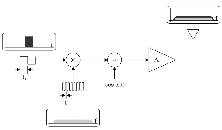
CDMA usesdirect-sequence spread-spectrum techniques to achieve efficient multiple access communications. In a direct sequence spread spectrum trans-mitter each bit of a binary nonreturn-to-zero information signal is modu-lated by one period of a binary nonreturn-to-zero pseudo-random sequence
to generate the transmitted signal, see Figure 2.1. This pseudo-random se-quence is also referred to assignature sequence,signature waveform, or in an older terminology code, explaining the term code-division multiple access. The pseudo-random sequence is composed of elementary pulses of duration
Tc commonly referred to as chips. Because the duration of a chip of the pseudo-random sequence is usually a factor between 31 and 128 smaller than the durationT of a bit of the information signal the modulated signal will be a wide-band signal with nearly the same spectrum as the pseudo-random sequence. The bandwidth expansion ratioT /Tc is also know as the
spreading gain. In a CDMA system the particular signature sequence of a user identifies the particular point-to-point channel corresponding to that user.
CDMA receivers employ the signature sequence of a user as the key to recover the transmitted information. Detection of the transmitted data is ac-complished with a correlation demodulator driven by a synchronized replica of the signature waveform used at the transmitter, see Figure 2.2. The by
Figure 2.1: Direct-sequence spread-spectrum transmitter
design low correlation between the signature waveforms of the different users gives the CDMA system its multiple access properties.
In an ideal CDMA system orthogonal signature sequences would be used. A CDMA system using orthogonal signature sequences will cancel out all multiple access interference and yield single user performance. However, fully orthogonal systems are not practical for two reasons. First, for a given limited number of chips there only exist a limited number of orthogonal signature sequences. Secondly, and more importantly, if the users are not transmitting synchronously, the signature sequences are out of phase and loose their orthogonal property. CDMA systems normally useshift-register sequences or combinations of shift-register sequences for their signature
2.1. CDMA PRINCIPLES 7
quences. It is not possible to obtain signature sequences for any pair of users that are orthogonal for all time offsets using this method.
Not having completely orthogonal signature sequences would not cause a dramatic performance decrease, if the received power of the interfering signal is smaller than the received power of the signal of the desired user. However, if the interfering signals are much stronger than the signal of the desired user, proper detection becomes impossible. This scenario occurs often in practical systems. For example consider the link from a cellular phone to a base station. If one cellular phone is transmitting from a position close to the base station and another cellular phone is transmitting from a position further away from the base station, then the received power of the signal of the first cellular phone will be higher than that of the distant cellular phone, assuming that their transmit powers are equal. Thus, the detection of the distant user will result in a severe increase in bit errors. This situation is generally called thenear-far problem.
A natural solution to the near-far problem is the use of power control. The power control system compares the received power levels. It uses a control channel to transmit power status information to the cellular phones. The cellular phone will adapt its transmitting power in such a way that the received power at the base station is equal for all users. Power control alleviates the near-far problem at the expense of receiver complexity and increased bandwidth. In the next chapter it will be shown that the near-far problem can also be solved by using detection techniques that are less sensitive to differences between the received signal powers of the users.
The length is another property of the signature sequences that has to be taken into consideration. Traditionally signature sequences with a length
N were used in CDMA so that N Tc =T, thus the period of the signature
sequence is equal to the duration of a bit, so each bit is modulated by the entire signature sequence. These kind of signature sequences are so called
short codes. The disadvantage of using signature sequences with a relatively short length is that the crosscorrelations between the signature sequences vary relatively strongly from each other. Since the crosscorrelations be-tween the signature sequence of a channel and the signature sequence of the other channels determines the amount of interference on the channel, vary-ing crosscorrelations will result in a bit-error-rate performance that varies between channels. To solve this so called long codes can be used.
Long codes are signature sequences with a period that is much longer than the duration of a bit, for example signature sequences with a period of 242Tc. When these signature sequences are used to modulate a bit stream
other channels. This results in an interference on each channel that varies from bit to bit, but averaged over the bits there will be the same amount of interference on each channel. Therefor the bit-error-rate performance on each channel will be the same.
The use of long codes is not the only solution to the problem of the varying bit-error-rate performance between channels of the traditional, short code, CDMA system. In the next chapter it will be shown that it is possible to develop detection techniques that remove or reduce multiple access inter-ference on a channel and thus remove or reduce the influence that multiple access interference has on bit-error-rate performance of a channel. But first, in the next section, mathematical models for CDMA systems will be given that can be used to develop and analyze CDMA detection techniques.
2.2
Continuous-time CDMA Models
In this section continuous time models are given of a CDMA system with a total number ofK users that transmit bits using binary antipodal modula-tion over a white Gaussian noise channel. These models are widely used in CDMA and multiuser detection literature. A good reference on this subject is the bookMultiuser Detection by Sergio Verd´u [15], on which this section is largely based. The notation used in the models assumes short code systems, but the models can be easily extended to long code systems.
2.2.1 Synchronous Channel
The basic synchronous K-user CDMA model describes the received signal of a CDMA system in whichK synchronous bit streams antipodally mod-ulateK signature waveforms which are transmitted over anAdditive White Gaussian Noise (AWGN) channel. Both the bit streams and the signa-ture waveforms are represented by non-return-to-zero (NRZ) signals. The received signal for one symbol period in such a system can be expressed as:
r(t) =
K
X
k=1
Akbksk(t) +σn(t). (2.1)
Where the following notation is used:
• sk(t) is the deterministic signature waveform assigned to thekth user,
normalized to have unit energy ||sk||2 =
Z T 0
sk(t)dt=trianleq1. (2.2)
2.2. CONTINUOUS-TIME CDMA MODELS 9
Figure 2.3: Definition of asynchronous crosscorrelations (k < l)
• Ak is the received amplitude of thekth user’s signal. A2k is referred to
as the energy of thekth user.
• bk∈ {−1,+1}is bit transmitted by the kth user.
• n(t) is white Gaussian noise with zero mean and unit variance. It models thermal noise plus other noise sources unrelated to the trans-mitted signals. According to (2.1) the noise power in a frequency band with bandwidth B is 2σ2B.1
The model above could for example describe the received signal on a forward link (base-station to mobile) in a CDMA cellular system, using a very basic channel assumption without fading or multipath.
In the next chapter it will be shown that the bit-error-rate performance of various demodulation strategies depends on the signal-to-noise ratios,
Ak/σ, and on the similarity between the signature waveforms, quantified by
their crosscorrelations defined as
ρjk ,hsj, ski=
Z T 0
sj(t)sk(t)dt. (2.3)
2.2.2 Asynchronous Channel
In cellular systems the reverse link (mobile-to-base-station) is often not syn-chronized. Therefore offsets τk ∈ [0, T), k = 1, . . . , K are introduced to
model the lack of alignment of the bit epochs of theK different users at the receiver. The symbol-epoch offsets are defined with respect to an arbitrary origin. The received signal during one frame time in such a system can be expressed as:
r(t) =
K
X
k=1
M
X
i=−M
Akbk[i]sk(t−iT −τk) +σn(t). (2.4)
Where the length of the frames transmitted by each user is assumed to be equal to 2M+ 1 bits.
1In the literature, the noise one-sided spectral level 2σ2 is frequently denoted byN
The asynchronous model (2.4) can be viewed as a special case of the synchronous model (2.1), what often simplifies the probability of error anal-ysis of detectors [10]. Each bit in (2.4){bk[i], k= 1, . . . , K;i=−M, . . . , M}
can be considered as coming from a different ‘user’ in a synchronous channel whose bit interval is [−M T, M T+ 2T]. In this view, the number of fictitious users is equal to (2M+ 1)K.
As already stated in section 2.2.1, the performance of various demod-ulation strategies depends on the crosscorrelations between the signature waveforms. For asynchronous CDMA, two crosscorrelations between every pair of signature waveforms have to be defined, that depend on the offset between the signals. This can be seen in Figure 2.3. This figure shows that one symbol time for user j overlaps with two symbol times for user k. When the offsetτj of user j is smaller than the offset τk of user k the two
crosscorrelations can be defined as:
ρjk(τ) ,
Z T
τ
sj(t)sk(t−τ)dt, ρkj(τ) ,
Z τ 0
sj(t)sk(t+T −τ)dt, (2.5)
whereτ ∈[0, T].
2.3
Discrete-time CDMA Models
Detectors commonly have a front-end whose objective is to obtain a discrete-time representation from the received continuous-discrete-time waveformr(t). One way of converting the received waveform into a discrete-time representation is to pass it through a bank of matched filters, see Figure 2.4, each matched to the signature waveform of a different user. The outputs of the matched filters are than sampled at the end of each bit period. In other words, the matched filter bank correlates the received signal with the signature waveform of each individual user. To perform matched filtering for a user, knowledge of the signature waveform and the timing of that user is required. In this section expressions are given for the sampled matched filter out-puts for synchronous as well as asynchronous systems, these results are again mainly taken from Verd´u [15].
2.3.1 Synchronous Channel
The matched filter bank correlates the received signal with the signature waveform of each individual user. The output of the matched filter for a userk for synchronous CDMA can therefor be expressed as:
yk =
Z T 0
2.3. DISCRETE-TIME CDMA MODELS 11
Figure 2.4: Bank of matched filters
= Z T 0 Ã K X k=1
Akbksk(t) +σn(t)
!
sk(t)dt (2.7)
= Z T
0
Akbk[i]sk(t) + X
j6=k
Ajbjsj(t) +σn(t)
sk(t)dt (2.8)
= Z T
0
Akbksk(t)sk(t)dt+
Z T 0
X
j6=k
Ajbjsj(t)sk(t)dt+
Z T 0
σn(t)sk(t)dt (2.9)
= Akbk
Z T 0
sk(t)sk(t)dt+
X
j6=k Ajbj
Z T 0
sj(t)sk(t)dt+
σ
Z T 0
n(t)sk(t)dt (2.10)
Now by using (2.3) and the fact thatsk(t) is normalized to have unit energy
the matched filter outputs can be expressed as
yk =Akbk+
X
j6=k
Ajbjρjk+nk, (2.11)
where
nk,σ
Z T 0
n(t)sk(t)dt (2.12)
Equation (2.11) can be written in vector form:
y=RAb+n, (2.13)
where
R = {ρjk}, (2.14)
y = [y1, . . . , yK]T, (2.15)
b = [b1, . . . , bK]T, (2.16)
A = diag{A1, . . . , AK}, (2.17)
n = [n1, . . . , nK]T (2.18)
(2.19) So n is a zero-mean Gaussian random vector with covariance matrix equal to
E[nnT] =σ2R. (2.20)
2.3.2 Asynchronous Channel
Using the same reasoning as for the synchronous channel and equations (2.4) and (2.5) the matched filter outputs in the case of asynchronous CDMA can be expressed as
yk[i] =Akbk[i] +
X
j<k
Ajbj[i+ 1]ρkj+
X
j<k
Ajbj[i]ρjk
+X
j>k
Ajbj[i]ρkj+
X
j>k
Ajbj[i−1]ρjk+nk[i], (2.21)
where
nk[i],σ
Z τk+iT+T
τk+iT
n(t)sk(t−iT −τk)dt, (2.22)
and it is assumed that τ1 ≤ τ2. . . ≤ τK, that is the users are labelled
chronologically, i.e. by their time of arrival.
Equation (2.21) can be written in matrix form:
y[i] =RT[1]Ab[i+ 1] +R[0]Ab[i] +R[1]Ab[i−1] +n[i], (2.23) where the zero-mean Gaussian processn[i] has autocorrelation matrix
E[n[i]nT[j]] =
σ2RT[1], ifj=i+ 1;
σ2R[0], ifj=i;
σ2R[1], ifj=i−1;
0, otherwise,
2.3. DISCRETE-TIME CDMA MODELS 13
Figure 2.5: K-dimensional channel of matched filter outputs for asyn-chronous CDMA channel.
and the matricesR[0] and R[1] are defined by
Rjk[0] ,
1, ifj =k;
ρjk, ifj < k; ρkj, ifj > k;
(2.25)
Rjk[1] ,
½
0, ifj≥k;
ρkj, ifj < k. (2.26)
The vector discrete-time model in (2.23) can be represented in the z -transform domain as
y[i] =S(z)Ab[i] +n[i], (2.27) where
S(z) =RT[1]z+R[0] +R[1]z−1 (2.28) is the discrete time channel transfer function, see Figure 2.5.
Chapter 3
Detection Techniques
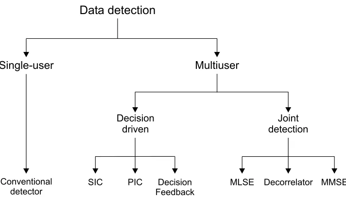
Several detection techniques for the CDMA channel have been studied in the literature. One way of categorizing them is to divide them into single-user and multisingle-user methods [8], see Figure 3.1. A single-user detector is defined as a receiver structure that requires no information regarding the other (interfering) users present in the system and demodulates the data signal of one user only.
From the definition of a single-user detector it follows that a multi-user detector is as a receiver structure that does require information regarding the other (interfering) users present in the system and demodulates the data signal of all users. Multiuser detection techniques can be divided into joint detection and decision-driven techniques. Injoint detection the front-end of the detector is traditionally (but not necessarily) a bank of matched filters followed by linear or nonlinear transformations on the matched filter outputs. Decision-driven techniques are characterized by the regeneration and subtraction of data estimates.
The goal of this chapter is to select the multiuser detection techniques that are best suited for implementation considering the performance level of the currently available hardware and the bit-error-rate performance levels that are currently requested from detection techniques for cellular wireless mobile telephony systems. Therefor the chapter starts with a discussion of the criteria for evaluation and comparison of the implementation related issues and performance levels of detection techniques. After that, several detection techniques for CDMA systems will be introduced. The first de-tector that will be discussed, the well-known conventional dede-tector, is an example of a single-user detector. The maximum likelihood sequence es-timator (MLSE) detector that is introduced subsequently is an example of a nonlinear joint detection technique. The decorrelating and minimum mean square error (MMSE) detector that are also discussed are examples of linear joint detection techniques. Examples of decision-driven multiuser detection techniques that are introduced in this chapter are the successive
Figure 3.1: Classification of detection techniques.
interference cancellation (SIC), parallel interference cancellation (PIC) and decision-feedback detectors. In the second last section of the chapter a com-parison of the introduced detectors will be given. The last section of this chapter summarizes the conclusions that can be drawn from the evaluation of the multiuser detection techniques performed in this chapter.
3.1
Evaluation Criteria for Detection Techniques
The evaluation criteria for detection techniques can roughly be divided into two categories: implementation related issues and performance measures. The implementation related issues that will be considered for the detectors discussed in this chapter are the received signal- and system parameters that have to be estimated or known by the receiver and the computational complexity of the detector. The performance measures that will be used are bit-error-rate and asymptotic multiuser efficiency.
The received signal- and system parameters that have to be estimated or known by the receiver are the signature waveforms, timing and received amplitudes of each user and the noise level. The detectors discussed in this chapter may require all, or only a subset of this information for demodulation of a user, which will be indicated in the section describing the detector. A detector that requires more information will increase the complexity of the receiver, because the information often has to be extracted from the received signal.
3.1. EVALUATION CRITERIA FOR DETECTION TECHNIQUES 17
detector to demodulate the transmitted information divided by the total number of demodulated bits. For multiuser detection techniques the com-plexity of demodulating the transmitted information of an individual user usually increases with the total number of users K in the system. A time complexity per bit off(K) is written asO(g(K)) if there exists a constant
c > 0 such that for large enough K, f(K) ≤ cg(K) [15]. In the sections describing the detectors, the computational complexity of each detector will be given for the synchronous as well as the asynchronous case.
The bit-error-rate or probability of error performance measure is the number of incorrectly detected bits relative to the total number of detected bits. For some detection techniques it is possible to derive an analytical expression for the bit-error-rate. However, for asynchronous systems this is often not straightforward and for some of the described detection techniques it is not possible at all. The only way to acquire a bit-error-rate for these detection techniques is from simulation results.
The asymptotic multiuser efficiency is an alternative performance mea-sure that is generally easier to derive than the actual probability of error. It measures the slope with which the bit-error-rate for thekth userPk(σ) goes to 0 (in logarithmic scale), asσgoes to 0. So in the high signal-to-noise ratio region. It indicates the performance of the detector when the interference caused by the other users is dominating over the noise. The asymptotic multiuser efficiency is defined as [15]
ηk , lim σ→0
ek(σ)
A2k , (3.1)
whereek(σ) is the effective energy of user k, defined as the energy that user
k would require to achieve a bit-error-rate equal to Pk(σ) in a single-user Gaussian channel with the same background noise level, that is,
Pk(σ) =Q
à p
ek(σ) σ
!
. (3.2)
where Q is is the complementary Gaussian cumulative distribution function:
Q(x) = Z ∞
x
1 √
2πe −t2/2
dt (3.3)
Figure 3.2: Conventional detector.
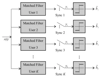
3.2
Conventional Detector
The conventional detector consists of the front-end with the bank of matched filters, used to obtain a discrete-time process from the received continuous-time waveform as described in section (2.3), followed by bit decisions directly based on the sign of the matched filter outputs
ˆbk= sgn(yk), (3.4)
see Figure 3.2. The signum function sgn is defined as sgn(x),
½
1 ifx >= 0
−1 ifx <0 (3.5)
The input of the signum function is often referred to as asoft decision, while the output of the signum function is often referred to as ahard decision.
Recall that yk is defined in (2.11) as yk=Akbk+
X
j6=k
Ajbjρjk+nk, (3.6)
for the synchronous case, or as
yk[i] =Akbk[i] +
X
j<k
Ajbj[i+ 1]ρkj+
X
j<k
Ajbj[i]ρjk
+X
j>k
Ajbj[i]ρkj+
X
j>k
3.2. CONVENTIONAL DETECTOR 19
in (2.21) for the asynchronous case.
The only received signal- and system parameters required by the con-ventional detector to detect a user is knowledge of the signature waveform and timing of that user.
Since the detection of a user is independent of the other users in the system the number of computations needed for detection does not increase with the number of users. Therefor the time complexity per bit of the conventional detector is constant.
To start the analysis of the bit-error-rate of the conventional detector it is illustrative to consider the case where the signature waveform of the kth user is orthogonal to the signature waveforms of all other users. In that case
ρjk equals zero when j 6=kand the output of the matched filter for user k
is reduced to that of the single user problem. The error probability for a single user in antipodal signaling is known to be
P(σ) =Q
µ
A σ
. (3.8)
Returning to the case of non-orthogonal codes it is illustrative to first analyze the two-user synchronous case before generalizing to the K-user case. To shorten the used notation ρ12 =ρ is used for the crosscorrelation between the signature waveforms of the two users. The error probability of the conventional detector for user 1 in the two-user synchronous case is:
P1 = P[b16= ˆb1]
= P[b1= +1]P[y1 <0|b1 = +1] +
P[b1=−1]P[y1 >0|b1 =−1]. (3.9) In the non-orthogonal case the matched filter output y1 is also dependent onb2. So in order to find the error probability further conditioning onb2 is needed:
P[y1 >0|b1=−1] = P[y1 >0|b1=−1, b2 = +1]P[b2= +1] +
P[y1 >0|b1=−1, b2 =−1]P[b2=−1] = P[n1 > A1−A2ρ]P[b2 = +1] +
P[n1 > A1+A2ρ]P[b2 =−1]
= 1
2Q µ
A1−A2ρ
σ
¶ +1
2Q µ
A1+A2ρ
σ
, (3.10) where the independence of the data bitsb1,b2and the noise termn1 is used. It is also assumed that the users transmit +1 and -1 with equal likelihood, settingP[b= +1] =P[b=−1] = 0.5 for both users. By symmetry the same expression is obtained for P[y1 <0|b1 = +1]. Therefore, the bit-error-rate of the conventional detector in the presence of one interfering user is
Pc1(σ) =
1 2Q
µ
A1−A2ρ
σ
¶ +1
2Q µ
A1+A2ρ
σ
where the superscriptc is used to indicate the conventional detector. The error probability for user 2 is found in a similar way which leads to a similar equation in which the indices 1 and 2 are interchanged.
In Verd´u [15] it is shown that the reasoning above can be generalized to an arbitrary number of usersK and to the asynchronous case. The proba-bility of error, or bit-error-rate of the conventional detector for synchronous CDMA can be expressed as (equation 3.90 in Verd´u):
Pck(σ) = 4K1−1
P
e1∈{−1,1}· · ·
P
ej∈{−1,1},j6=k· · ·
P
eK∈{−1,1}Q
³
Ak
σ +
P
j6=kej Aj
σ ρjk
´
. (3.12)
For asynchronous CDMA the probability of error function becomes (equa-tion 3.104 in Verd´u):
Pck(σ) = 4K1−1
P
(e1,d1)∈{−1,1}2· · ·
P
(ej,dj)∈{−1,1}2,j6=k· · ·
P
(eK,dK)∈{−1,1}2Q
³
Ak
σ +
P
j6=k Aj
σ (ejρjk+djρkj)
´
. (3.13) In these equations ej and dj represent the values of the bits on which the
probability of error is conditioned.
The asymptotic multiuser efficiency of the conventional detector for syn-chronous CDMA is equal to (equation 3.122 in Verd´u)
ηkc = max
0, 1−X
j6=k Aj Ak|
ρjk|
2 . (3.14)
For asynchronous CDMA the asymptotic multiuser efficiency becomes (equa-tion 3.124 in Verd´u):
ηkc = max
0, 1−X
j6=k Aj Ak
(|ρjk|+|ρkj|)
2 . (3.15)
Therefor the asymptotic multiuser efficiency of the conventional detector for the two-user synchronous case is equal to
ηkc = µ
max ½
0, 1−A2
A1|
ρ|
¾¶2
. (3.16)
3.3. MAXIMUM LIKELIHOOD SEQUENCE ESTIMATOR DETECTOR 21
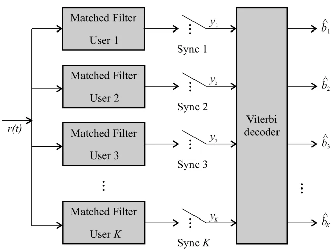
Figure 3.3: MLSE detector.
amplitude of user 1. When the amplitude of user 2 is huge compared to the amplitude of user 1 the asymptotic multiuser efficiency will become 0. This means that the bit-error-rate plot of the conventional detector for high signal-to-noise ratios goes to 0 (in logarithmic scale) with slope 0, or in other words the bit-error-rate of the detector does not improve when the signal-to-noise ratio improves.
3.3
Maximum Likelihood Sequence Estimator
De-tector
The maximum likelihood sequence estimator (MLSE) detector consists of a bank of matched filters, followed by an algorithm that chooses the input sequence b that maximizes the likelihood function of the matched filter outputsy. So for the synchronous case
ˆ
b= arg max
b∈{−1,+1}Kp(y|b), (3.17)
and for the asynchronous case ˆ
b= arg max
b∈{−1,+1}K(2M+1)p(y|b), (3.18)
In the synchronous case this is equivalent to finding the hypothesis that minimizes the payoff function [11]:
Ω(b) = Z T
0 "
r(t)−
K
X
k=1
Akbksk(t)
#2
dt. (3.19)
If the asynchronous channel is considered as aK(2M+ 1)-user synchronous channel maximizing the likelihood function of the matched filter outputs is equivalent to finding the hypothesis that minimizes the payoff function [15]:
Ω(b) =
Z M T+2T
−M T
[r(t)−St(b)]2dt (3.20)
for the asynchronous case, where
St(b) = K
X
k=1
M
X
i=−M
Akbk[i]sk(t−iT −τk). (3.21)
Therefor the maximum likelihood sequence estimator detector requires the following received signal- and system parameters at the receiver: the received amplitudes of all the users, the timing of the desired user, the timing of the interfering users and the signature waveforms of the desired and interfering users. In the synchronous case the requirement of knowledge of the timing of the interfering users can of course be dropped.
It can be shown [15] that generation of all the values of Ω(b) for the syn-chronous case can be done in a tree structure that takesO(2K) operations.
The selection of the optimum b can then be done in O(2K) operations, so the time complexity per bit isO(2K/K). The payoff function for the asyn-chronous case (3.21) can be expressed as a sum of (2M+1)Kterms such that each term depends onK components of b and any consecutive terms share
K−1 arguments. An expression of that type can be maximized in O(2K) operations [15] using a real-time version of dynamic programming called the
Viterbi Algorithm, so the time complexity per bit for the asynchronous case is alsoO(2K/K). The maximum likelihood sequence estimator detector for the asynchronous case is shown in Figure 3.3.
It is not possible to derive a closed-form analytical expression for the bit-error-rate of the maximum likelihood sequence estimator detector. However it is possible to derive an equation for the asymptotic multiuser efficiency (equation 4.91 in Verd´u):
ηkl = min
²∈{−1,0,1}K,² k=1
1
A2k²
TARA², (3.22)
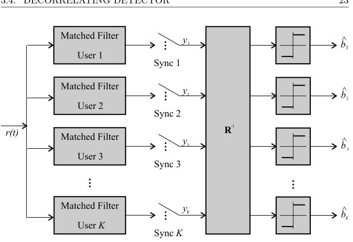
3.4. DECORRELATING DETECTOR 23
Figure 3.4: Decorrelating detector.
between any pair of distinct transmitted vectors. The set of error vectors that affects thekth user is
Ek={²∈ {−1,0,1}K, ²k 6=0}. (3.23)
3.4
Decorrelating Detector
The decorrelating detector consists of a bank of matched filters followed by a linear transformation that multiplies the output of the matched filter bank with the inverse of the correlation matrix, see Figure 3.4. This removes all the interference for a user k, caused by any of the other users. The only source of interference left is the enhanced background noise equal toR−1n. The bit decisions are then made based on the signs of the outputs of the linear transformation. So for the synchronous case:
ˆ
bk = sgn((R−1y)k), (3.24)
For the asynchronous caseR−1 is replaced with the inverse of the discrete-time channel transfer function (2.28)
ˆb
k= sgn((S−1(z)y)k), (3.25)
with
From these equations it can be seen that the decorrelating detector requires knowledge of the following received signal- and system parameters: the tim-ing of the desired user, the timtim-ing of the interfertim-ing users and the signature waveforms of the desired and the interfering users.
The required number of operations needed for detection of a user in-creases linearly with the number of users K, therefor the time complexity per bit of the decorrelating detector isO(K) for the synchronous as well as the asynchronous case. It can be shown [15] that the decorrelating detector can be implemented as a matched filter detector with modified filter coeffi-cients. The computational complexity of that implementation is identical to that of the conventional detector. A problem of both implementations of the decorrelating detector is that if the crosscorrelations have to be calculated re-peatedly, for example due to varying channel conditions, not only they have to be generated from the replicas of the received signature waveforms, but a matrix inversion of the correlation matrix has to be performed as well. Us-ing Gaussian elimination this has a computational complexity ofO(K3). A similar problem arises when long codes are used, because than the signature waveforms vary for each transmitted bit, also causing repeated calculation of the crosscorrelations and the inverse of the crosscorrelation matrix.
If the normalized crosscorrelations among all the signature waveforms are very small, the processing of the matched filter outputs with the matrix
R−1 can be approximated by processing the matched filter outputs with 2I−R. This detector is called the approximate decorrelator. An analog approximation can be used in the asynchronous case. If the crosscorrela-tions have to be calculated repeatedly, this approximation has the advan-tage that it does not require any processing of the crosscorrelations supplied by the crosscorrelators of the replicas of the signature waveforms. The ap-proximate decorrelator is particularly advantageous in those asynchronous CDMA channels where the period of the signature waveform is much longer than the symbol period. In those cases, the crosscorrelations keep changing and it is cumbersome to repeatedly perform the matrix inversion required by the decorrelating detector.
The probability of error of the decorrelating detector for synchronous CDMA can be expressed as (equation 5.42 in Verd´u):
Pdk(σ) =Q
Ak σ
q
R+kk
, (3.27)
where + is used as a shorthand for the inverse of a matrix, so R+kk is a shorthand for elementkkof theR−1 matrix, (R−1)kk and the superscript d
is used to indicate the decorrelating detector. The (asymptotic) multiuser efficiency of the decorrelating detector for synchronous CDMA is equal to
ηkd= 1
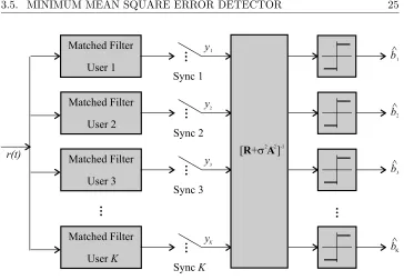
3.5. MINIMUM MEAN SQUARE ERROR DETECTOR 25
Figure 3.5: MMSE detector.
The bit-error-rate of the asynchronous decorrelating detector is equal to (equation 5.57 in Verd´u)
Pdk(σ) =Q
Ak
q
ηd k σ
, (3.29)
whereηdkis the (asymptotic) multiuser efficiency of the asynchronous decor-relating detector that is equal to
ηdk= µ
1 2π
Z π
−π
[RT[1]ejω+R[0] +R[1]e−jw]+kkdω
¶−1
. (3.30)
3.5
Minimum Mean Square Error Detector
The minimum mean square error (MMSE) detector consists of a bank of matched filters followed by a linear transformation, see Figure 3.5, that maximizes the signal-to-interference ratio at the output of the linear trans-formation. For the synchronous case it can be shown [15] that this transfor-mation has to be equal to:
ˆbk= sgn((My)k) with M= (R+σ2A−2)−1. (3.31) where
σ2A−2 = diag ½
σ2
A21, . . . , σ2
A2K
¾
For the asynchronous case, the MMSE linear detector is a K-input, K -output, linear time-invariant filter with transfer function
[RT[1]z+R[0] +σ2A−2+R[1]z−1]−1. (3.33) The MMSE detector can be seen as a compromise solution between the conventional detector and the decorrelating detector. The conventional de-tector is optimized to fight the background noise exclusively, whereas the decorrelating detector eliminates the multiaccess interference disregarding the background noise. In contrast, the MMSE detector takes into account the relative importance of each interfering user and the background noise.
To construct the linear transformation the MMSE detector requires know-ledge of the following received signal- and system parameters: the timing of the desired user, the timing of the interfering users, the noise level at the receiver, the received amplitudes and the signature waveforms of the desired as well as the interfering users.
Since the MMSE detector performs a similar transformation as the decor-relating detector its time complexity per bit is alsoO(K) for the synchronous case as well as the asynchronous case. Just as the decorrelating detector, the MMSE detector can also be implemented as a matched filter detector with modified filter coefficients. The computational complexity of that implemen-tation is identical to that of the conventional detector. The MMSE detector also has the disadvantage that it requires a matrix inversion, which has to be performed again and again when the crosscorrelations change because the channel conditions vary or because long codes are used.
The probability of error of the MMSE detector for synchronous CDMA is equal to (equation 3.124 in Verd´u)
Pmk(σ) = 21−K
P
e1∈{−1,1}· · ·
P
ej∈{−1,1},j6=k· · ·
P
eK∈{−1,1}
Q
µ
Ak
σ
(MR)kk
√
(MRM)kk
³ 1 +P
j6=kβjbj
´
, (3.34)
where,
Bj =Ak(MR)kj, (3.35)
and
βj = Bj Bk
. (3.36)
The superscript m is used to indicate the MMSE detector. Equation 3.34 can also be used for asynchronous systems when an asynchronous system is viewed as a special case of a synchronous system as discussed in section 2.2.2. Of course the dimensions of the matrices in (3.34) change, since the equivalent synchronous system has (2M+ 1)K fictitious users.
3.5. MINIMUM MEAN SQUARE ERROR DETECTOR 27
decorrelator:
ηkm= 1
R+kk. (3.37)
in the synchronous case, and
ηkm= µ
1 2π
Z π
−π
[RT[1]ejω+R[0] +R[1]e−jw]+kkdω
¶−1
. (3.38)
in the asynchronous case.
Compared to the decorrelating detector the MMSE will therefor only offer a slightly increased performance in low signal-to-noise ratio channels. In exchange for that slight increase in performance, the MMSE detector requires knowledge of the noise level at the receiver, which increases the complexity of the receiver. The main advantage of the MMSE detector is the ease with which it can be implemented adaptively. In literature, two types of the adaptive MMSE detector are described [15].
The first type of adaptive MMSE detectors uses training sequences. A training sequence is a string of data known to the receiver. When the adap-tive MMSE detector receives the training sequence it uses an adaptive law to adjust its linear transformation. By doing so, the receiver learns the impulse response of the channel. If the impulse response of the channel changes over time, training sequences can be sent periodically to readjust the receiver. It can be shown [15] that the solution to which the adaptation law converges is the MMSE detector. The only knowledge needed by the adaptive MMSE detector is the timing of the desired user and the training sequence. When the adaptive MMSE detector is implemented as a matched filter detector with modified matched filter coefficients its time complexity per bit is con-stant, just as that of the conventional detector. Of course the matched filter coefficients still have to be calculated when the training sequence is received, but this requires far less operations than calculating and inverting the trans-formation matrix. Implementation of the adaptive MMSE detector for long code CDMA systems is not possible because in those systems the signature waveforms change for each bit, which would require adaptation of the detec-tor for each bit and thus transmission of the training sequence for each bit. This causes of course way to much overhead for practical implementation.
Figure 3.6: SIC detector.
coefficients, resulting in a constant time complexity per bit. Unfortunately the blind adaptive MMSE detector does not work for long code systems, because for each bit it would have to adapt to the section of the signature waveform that is used to modulate that bit.
3.6
Successive Interference Cancellation Detector
The successive interference cancellation (SIC) detector is a detector that belongs to the class of driven detectors. The idea behind decision-driven detectors is simple: if a decision has been made about an interfering user’s bit, then that interfering signal can be subtracted from the received waveform. This will cancel the interfering signal, provided that the decision was correct; otherwise it will double the contribution of the interferer.
The simplest form of the SIC detector consists of a bank of matched filters followed by a sorter, see Figure 3.6. In a lot of implementations the sorter sorts the signals of the different users in order of decreasing received energies. However, this is not necessarily best since it fails to take into account the crosscorrelations among users. A sensible alternative is to order users according to the signal-to-noise ratios computable using
E
" µZ T
0
r(t)sk(t)dt
¶2#
=σ2+A2k+X
j6=k
A2jρ2jk, (3.39)
3.6. SUCCESSIVE INTERFERENCE CANCELLATION DETECTOR 29
user k. For the synchronous case this results in the following decision rule
ˆ
bk= sgn
yk−
k−1 X
j=1
Ajρjkˆbj
, (3.40)
where it is assumed that the users are numbered in order of decreasing re-ceived energies or signal-to-noise ratios, so the user with the highest rere-ceived energy or signal-to-noise ratio has the lowest number.
Up to now it was assumed that the users in the asynchronous channel are numbered so that their offsets are increasing, and, thus, the jth user’s bit that overlaps with bk[i] on the right side is bj[i] if j > k. However,
as already indicated for the synchronous case, for successive interference cancellation it is convenient to number the users in the (inverse) order they are cancelled, which is, normally, dictated by their relative received powers or matched filter outputs. So in the asynchronous case it is also assumed that the users are numbered in order of decreasing received energies or signal-to-noise ratios, so the user with the highest received energy or signal-to-signal-to-noise ratio has the lowest number. In order to still be able describe the successive interference cancellation detector in the asynchronous case it is useful to introduce the following notation:
δkj = 1{τk< τj}, (3.41)
so δkj equals 1 when τk < τj and 0 otherwise. Then bk[i] overlaps on the
right side with bj[i−δkj+ 1] and overlaps on the left side with bj[i−δkj].
It is now possible to generalize (3.40) to
ˆbk[i] = sgn yk[i]−
k−1 X
j=1
Aj(ρjkˆbj[i−δkj] +ρkjˆbj[i−δkj+ 1])
The following knowledge about the received signal- and system param-eters is required at the receiver by the SIC detector: the timing of the desired user, the timing of the interfering users, the received amplitudes and the signature waveforms of the desired and interfering users.
To detect a user the successive interference cancellation detector requires a number of operations that increases linearly with the number of usersK. Therefor the time complexity per bit of the SIC detector is O(K). The decision rule (3.40) indicates that the SIC detector requires the crosscorre-lations between the signature waveforms. This causes some problems when the SIC detector has to be used in long code CDMA systems, because in that case the crosscorrelations will have to be calculated for each transmit-ted bit. Fortunately this operation is a lot less complex than the matrix inversion that would be required for each bit in the long code version of the decorrelating or MMSE detector, or the adaptation that would have to be performed for each bit in the blind adaptive MMSE detector. Therefor using the SIC detector is still feasible for long code CDMA systems.
Using (2.11) and (3.40) the following expanded decision rule can be ob-tained
ˆbk= sgn
Akbk+nk+
k−1 X
j=1
Ajρjk(bj−ˆbj) + K
X
j=k+1
Ajρjkbj
. (3.43)
Since the cancellation residuals depend on the other random variables inside the sign function, an analytical exact evaluation of bit-error-rate is difficult and only possible for very small numbers of users K. Unfortunately it is not possible to obtain an analytical expression for the multiuser efficiency either. Therefor performance measures for the successive interference can-cellation detector can only be obtained by simulations or trough analytical approximations.
3.7
Parallel Interference Cancellation Detector
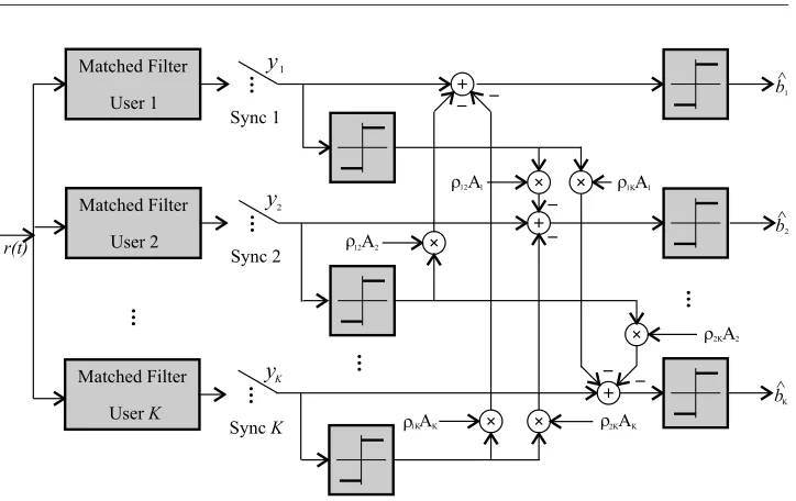
3.7. PARALLEL INTERFERENCE CANCELLATION DETECTOR 31
Figure 3.7: Two stage PIC detector
all other users, see Figure 3.7. So the second stage in fact performs successive cancellation for all users. This leads to the following decision rules:
ˆbk= sgn yk−
X
j6=k
Ajρjkˆbj
(3.44)
for synchronous CDMA and
ˆb
k = sgn
yk−
X
j<k
Aj(ρkjˆbj[i+ 1] +Ajρjkˆbj[i])
−X
j>k
Aj(ρkjˆbj[i] +Ajρjkˆbj[i−1])
(3.45)
for asynchronous CDMA.
the delay in demodulating signals in the PIC detector does not increase with the number of users.
The parallel interference cancellation detector requires the knowledge of the same received signal- and system parameters at the receiver as the suc-cessive interference cancellation detector. So it requires information about: the timing of the desired user, the timing of the interfering users, the re-ceived amplitudes and the signature waveforms of the desired and interfering users. The time complexity per bit of the PIC detector is comparable to the time complexity per bit of the SIC detector, it also increases linearly with the number of users and is therefor O(K). The PIC detector also re-quires the crosscorrelations between the signature waveforms, just as the SIC detector. This of course causes the problem that these crosscorrelations have to be calculated for each transmitted bit in long code CDMA systems. However, this is not such a complex operation that implementation of PIC detection in long code CDMA systems becomes infeasible. Obtaining an-alytical results for the bit-error-rate or asymptotic multiuser efficiency of the PIC detector is unfortunately not possible, the only way to obtain these performance measures is again trough simulation results.
A very useful property of the parallel interference cancellation detector is that it can be used for combining different detection techniques. For ex-ample, the first stage of the PIC detector can be replaced by a decorrelating detector, thus improving performance, but of course also increasing com-putational complexity. Another way of expanding the parallel interference cancellation detector is adding more stages. This will however not always increase performance and in some cases adding another stage may actually hurt performance.
3.8
Decorrelating Decision-Feedback Detector
In this section the decorrelating decision-feedback detector is discussed. Decision-feedback detectors are decision-driven multiuser detectors that com-bine several of the features of the decision-driven detectors that were dis-cussed in the previous sections:
• As in successive cancellation, the intermediate decisions used in deci-sion-feedback detectors are final (output) decisions.
• Decision-feedback detectors operate sequentially, demodulating one bit at a time.
inter-3.8. DECORRELATING DECISION-FEEDBACK DETECTOR 33
Figure 3.8: Synchronous decorrelating decision-feedback detector.
ference, whereby previous output (”final”) decisions are used as a surrogate transmitted data to cancel intersymbol interference.
The synchronous decorrelating decision-feedback detector consists of a bank of matched filers followed by a sorter and two transformations, see Figure 3.8. The sorter sorts the signals of the different users in order of decreasing received energies. In order to obtain the two transformations a Cholesky decompositionR=FTF(Fis lower triangular) of the correlation matrix is used [15].
The first transformation is a forward filter (FT)−1 that eliminates mul-tiuser interference, yielding the whitened matched filter outputs
¯
y=F−Ty=FAb+n,¯ (3.46)
where n¯ is a Gaussian K-vector with independent components, each with variance σ2. Since F is lower triangular, the first whitened matched filter output is
¯
y1 =F11A1b1+ ¯n1. (3.47) Thus, ¯y1 contains no interference from other users. For k > 1, ¯yk does
contain interference from lower-numbered users:
¯
yk=FkkAkbk+ k−1 X
j=1
FkjAjbj + ¯nk. (3.48)
Following the philosophy of successive cancellation the users can be demod-ulated sequentially by
ˆ
bk= sgn
y¯k−
k−1 X
j=1
FkjAjˆbj
Figure 3.9: Asynchronous decorrelating decision-feedback detector. The reconstruction of the multiaccess interference from the detected bits can be written in matrix form as (F−diag{F})Aˆb, which is the second trans-formation in Figure 3.8 that performs a feedback filter operation . Using this expression the decision rule 3.49 can be written in matrix notation as:
ˆ
b= sgn(F−Ty−(F−diag{F})Aˆb). (3.50) For asynchronous CDMA the feed-forward and feedback filters of the decorrelating decision-feedback detector (figure 3.9) have K ×K transfer functions [15]:
G(z) = [F[0] +F[1]z]−T, (3.51)
B(z) = F[0]−diag{F}[0] +F[1]z−1. (3.52) Where F[0] is a lower triangular matrix and F[1] is an upper triangular matrix with zero diagonal which can be found by factoring the discrete time channel transfer function (2.28) as
3.9. COMPARISON OF DETECTION TECHNIQUES 35
Implementation of the feed forward and feedback filtering of a decorre-lating decision-feedback detector requires a number of operations that in-creases linearly with the number of users. This results in a time complexity per bit ofO(K). However the other operations involved in the decorrelat-ing decision-feedback detector like sortdecorrelat-ing of the users accorddecorrelat-ing to their received energies, generation of the forward filter using a Cholesky decom-position and inversion of the resulting triangular matrix, make the decorre-lating decision-feedback detector more computationally intensive than the other decision-driven detectors. The decorrelating decision-feedback detec-tor also has the disadvantage that these operations have to be performed again and again when the channel conditions vary or when long codes are used, making implementation of the decorrelating decision-feedback detector less feasible in these systems.
The decorrelating decision-feedback detector is the only non-linear mul-tiuser detector for which it is possible to obtain a closed-form expression for the probability of error for an arbitrary number of users and arbitrary cross-correlation matrices. This expression is equal to (equation 7.68 in Verd´u)
Pddfk (σ) = 21−k X (b1,...,bk−1)∈{−1,1}
k−1
X
(ˆb1,...,ˆbk−1)∈{−1,1}
k−1
πk(b1−ˆb1, . . . , bk−1−ˆbk−1) ×
k−1 Y
j−1
[1{bj = ˆbj}+ (1−2 1{bj = ˆ(b)j})
×πj(b1−ˆb1, . . . , bj−1−ˆbj−1)], (3.54) where
πk(e1, . . . , ek−1) =Q Ã
Fkk Ak
σ +
k−1 X
l=1
Fkl Al
σ el
!
. (3.55)
Here the superscript ddf is used to indicate the decorrelating decision feed-back detector.
3.9
Comparison of Detection Techniques
Figure 3.10: Capacity curves for perfect power control (Eb/N0 = 8dB and processing gain = 31) [2] .
estimator (MLSE) detector, on the basis of common assumptions. The re-sults published in this paper will be used here to compare the bit-error-rate performance of the different multiuser detectors.
Figure 3.10 contains a plot of the capacity curves taken from [2] for a CDMA system with signal-to-noise ratio Eb/N0 = 8-dB, spreading gain
N = 31, so 31 chips per symbol and perfect power control and therefor equal received energies. WhereEb is the energy of a bit equal toA2k andN0 is the one sided spectral level equal to 2σ2. The simulated Parallel IC detector has a conventional first stage followed by two cancellation stages.
3.9. COMPARISON OF DETECTION TECHNIQUES 37
Figure 3.11: BER versus Eb/N0 with perfect power control (ten users and processing gain = 31) [2].
The linear detectors in group two roughly support three times the number of users of the conventional detector for a given probability of error, while the two nonlinear detectors in group one support four times the number of users of the conventional detector for a given bit-error-rate. The performance of the successive interference cancellation (SIC) detector is significantly poorer due to lack of variance in the received signal powers.
3.9. COMPARISON OF DETECTION TECHNIQUES 39
Figure 3.12 presents the bit-error-rate performance of the receivers in the presence of two interfering users, one with equal power to the desired user and one with a power which varies from 10-dB below the desired user to 30-dB above the desired user. Therefor this figure will give an indication of the near-far resistance of the different detection techniques. As expected, the conventional detector degrades quickly in the presence of strong inter-ference. The SIC detector and the decorrelating decision-feedback detector which benefit from diverse powers are found to be robust to strong inter-ferers, as is the decorrelating detector which has a performance which is independent of the user energies. The MMSE detector having a theoretical near-far resistance identical to the decorrelating detector also displays ro-bustness. The PIC detector is not as robust and shows slow degradation for high interference power. This is caused by the fact that estimation of the amplitude of the weak user is inaccurate in the first stage of cancellation due to the dominating interference, resulting in inaccurate cancellation of the weak user’s signal from the strong users signal. This results in an unre-liable estimate of the signal of the strong user, causing problems when the strong user’s signal is cancelled from the weak user’s signal in the second stage. One way of improving the parallel interference cancellation receiver in such situations would be to avoid cancelling the weak user since its am-plitude estimation is unreliable.
Asymptotic multiuser efficiency plots for multiuser detectors are found less frequently in literature. Fortunately the asymptotic multiuser efficiency can, at least for 2 user systems, be determined analytically for all discussed multiuser detectors [15].
0 0.5 1 1.5 2 2.5 3 3.5 4 0
0.1 0.2 0.3 0.4 0.5 0.6 0.7 0.8 0.9 1
A2/A1
Asymptotic Efficiency User 1
Asym. eff. A2/A1 plot, 2−users, ρ=0.6
Conventional Detector MLSE Detector
Decorrelating Detector / MMSE Detector /DDF Detector SIC Detector / PIC Detector
PIC Decorrelating First Stage Detector
Figure 3.13: Asymptotic efficiency for a 2 user synchronous system with
3.9. COMPARISON OF DETECTION TECHNIQUES 41
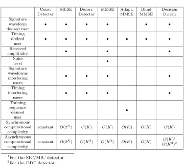
Conv. MLSE Decorr. MMSE Adapt. Blind Decision Detector Detector MMSE MMSE Driven Signature waveform desired user • • • • • • Timing desired user • • • • • • • Received
amplitudes • • •
Noise level • Signature waveforms interfering users • • • • Timing interfering users • • • • Training sequence desired user • Synchronous computational complexity
constant O(2K) O(K) O(K) O(K) O(K) O(K)
Asynchronous computational complexity
constant O(2K) O(K3) O(K3) O(K) O(K) O(K)1 O(K3)2
1For the SIC/MIC detector
2For the DDF detector
Table 3.1: Summary of requirements and computational complexity of mul-tiuser detection techniques.
energy is small, resulting in inaccurate cancellation of the interferers signal. When the received energy of the interferer increases, the decisions about the interferers transmitted bit become more reliable and the accuracy of the cancellation improves. The asymptotic multiuser efficiency for user 1 of the two-user decorrelating decision feedback (DDF) detector is equal to that of the decorrelating detector. For user 2 the asymptotic multiuser effi-ciency of the decorrelating decision feedback detector is equal to that of the multistage interference cancellation detector with decorrelating first stage. Therefor this asymptotic multiuser efficiency is plotted in the figure as well. The plot shows that on average the decorrelating decision feedback detector will perform better in high interference situations than the decorrelating as well as the PIC detector.
Decorrelating Decision Feedback) are summarized in the decision driven col-umn, since they all require the same information about the received signal-and system parameters at the receiver signal-and have the same computational complexity.
A detector that requires knowledge of more received signal- and system parameters at the receiver will increase the complexity of the receiver, be-cause the information will have to be extracted from the received signal. The table shows that all multiuser detection techniques require knowledge about more received signal- and system parameters at the receiver than the conventional detector and thus require a more complex receiver, except for the adaptive and blind MMSE detectors. The adaptive MMSE detector however uses training sequences whose transmission requires bandwidth.
All detectors in the table have higher computational complexity require-ments than the conventional detector. The MLSE detector has a compu-tationa