Application of Immune Feedback Control Algorithm
Based on BP Network Approximation in Intelligent
Vehicle Steering System
https://doi.org/10.3991/ijoe.v15i09.10584
Yanting Lan
North University of China, Taiyuan, China [email protected]
Xiaodong Chen
China Agricultural University, Beijing, China
Abstract—Steering system of intelligent vehicle is very difficult to execute precise control in driving due to many known and unknown disturbances. Therefore, design of steering algorithm has to be feasible for uncertain external interference, such as uneven pavement and horizontal wind, with automatic cor-rection function for changes in the location of intelligent cars caused by road tilt and horizontal wind. As traditional PID control is impossible to meet the con-trol requirements, according to mechanism of biological immunity, an immune feedback control method was proposed to approximate nonlinearity of T and B cells by BP network. Joint simulations of serpentine condition were carried out by Carsim and Simulink. The results show that trajectory tracking error, operat-ing load, risk of rollover and slip and control stability of control system are syn-thetically evaluated. The comprehensive evaluation index of automatic steering algorithm under high speed operation is fairly advantageous. Experimental re-sults also show that the algorithm effectively realizes tracking of intelligent ve-hicle for marking lines and avoidance of obstacles.
Keywords—Intelligent vehicle, steering system, Immune Feedback Control, BP network
1
Introduction.
Steering performance of smart car reflects its operability. In steering, with each wheel subjected to a force, changes of the lateral angle in uncertainty and load trans-ferred, force of each tire susceptible uncertainty and non-linearity of steering system. For so complicated reasons, conventional PID control could not achieve the require-ment[1-12], so the author designed IFC(Immune Feedback Control), in which con-struction of antibody suppression regulatory function was one of the difficulties. In literature[13-14], was selected as a radial symmetric nonlinear function, which required reasonable adjustment of immune parameters and antibody
con-()× f
K 、 、h
centration coefficient .In literature [15-17], a two-dimensional fuzzy controller was used to approximate the nonlinear function. The fuzzy controller contained two inputs
and one output, as was the input language variable and
was the output language variable of the fuzzy controller. BP net-work was utilized to approximate functions of antibody promotion and inhibition regulation of T cell.
2
Immune Feedback Control Rules
Immune feedback control rules [18-20]were a designed principle to control refer-ring to biological immune mechanism. Let the concentration of B cells in k generation be
(1)
Where ; , was antigen
concentra-tion of k generaconcentra-tion; , promotion factor of Th cell; , inhibitory factor of Ts cell; , B cell concentration changes; d, immune response of immune system to anti-gen delay time; ,a non-linear function, immune effect after interaction of antibod-ies and antigens secreted of k-d generation B cells, and . In ,
represented ratio of Ts cells to Th cells.
In different stages of body's immune feedback process, was used to indicate immune regulation function in early, late and end immune responses of three different stages, and the corresponding values were -1,1,1.
When number of antigens was deviation , and , concentration of B cells, was as control state , the immune feedback control principle was
.
3
Design of Immune Feedback Controller
Immune feedback control principle was combined with conventional PID control to be designed as a PID self-tuning immune feedback controller (IFC), which improved control performance of the system.
PID controller output:
(2) a
(k d) (uk d) u - ,D
-(
) (
)
(
uk d uk d)
f - ,D
-( )
( )
[
(
)
]
( )
(
)
[
]
{
f
B
k
d
} ( )
k
K
k
d
k
B
f
K
k
K
k
Ts
k
Th
k
B
e
h
e
e
-D
-=
-D
-=
-=
1
)
(
)
(
1 2( )
k K( )
kTh = 1e Ts
( )
k =K2f[
ÑB(
k-d)
]
e( )
k e( )
k1
K K2
( )
k B D( )
× f()
× ³0f K=K1
h h=K2/K1,
l
l
( )
ke e
( )
k B( )
k( )
ku
( )
k K{
f[
u(
k d)
]
} ( )
ek u = 1-lh D-( )
e( )
kz z z K K k
u i d
p PID ÷÷ ø ö çç è
æ +
-+
= K 1
Where, Kp, Ki, Kd was gain parameter, integral action parameter, the differential action parameter; z was the zero order maintainer. As output of PID controller to be the amount of external substance, IFC controller was as following
(3)
Where, was inhibition parameter of control stability(when increased, the system overshoot value decreased); Kp controlled response speed(when Kp increased, the response speed increased). Reasonable adjustment of and made system a small-er ovsmall-ershoot value and fastsmall-er response speed. The PID IFC controllsmall-er compensated for control error caused by noise or non-linear interference.
Parameters met requirement of the following relationship: .
If , an inverse feedback control action was performed; if , a positive feedback control action was performed. While upper limit of affected stability of control system, when , IFC was the same as conventional PID controller.
4
Simulation Test
4.1 Simulation analysis
Model of immune feedback control system was established in Matlab/Simulink, and the complex vehicle model in Carsim was imported into Simulink for joint simu-lation. In immune feedback controller, immune parameters , , delay time ,action coefficient of antibody concentration , threshold , thresh-old . Vehicle and simulation parameters :Weight of vehicle,1712 m/kg, Mo-ment of inertia,4165I/(kg.m2), Front wheelbase, 1.223L
a/m, Backshaft, 1.459Lb/m, Cornering stiffness of front wheel, 66896Ca/(N.rad-1) and Cornering stiffness of rear wheel, 62658Ca/(N.rad-1).Simulation tests were carried out for automatic steering system in serpentine conditions, and the results were analyzed.
Serpentine condition was an important working condition for stability evalua-tion of vehicle to evaluate driving stability comprehensively, referring to GB/T6323.1-9 for setting of serpentine simulation road conditions. Simulation test was performed at vehicle speed of 30m/s, with the designed immune feedback controller. Intelligent vehicle tracking trajectory is shown in figure 1.
( )
{
[
(
)
]
}
e( )
kz z K z k d k u f K k u d i p ÷÷ ø ö çç è
æ +
-+ = -= 1 1 1
1 h D
h h
h Kp
(
Kp,Ki,Kd)
>0,h³0( )
[
]
10<hf Duk £
( )
[
uk]
f D h <1
h h=0
1 =
K h=0.2 1
=
d a=10 e0=0.95
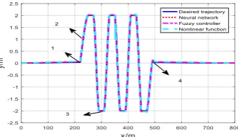
Fig. 1. Intelligent vehicle tracking trajectory
In Fig.1 , the tracking trajectory was basically the same as desired trajectory. Non-linear characteristics of immune feedback controller were fitted with radial symmetric nonlinear function, fuzzy controller and BP network. The simulation results showed that BP network approximation was better than the other two in simulation experi-ment of serpentine tracking. Transverse tracking error of vehicle in whole serpentine simulation experiment was controlled within ±0.11m, which maximum was 0.19m, and the control precision was satisfactory.
Steering angles and steering torques of vehicle are shown in figures 2 A & B re-spectively.
Fig. 2. A. steering wheel Angle B .Steering torque
It could be seen from Fig.2 A & B that the steering torque was comparatively large in simulation test of whole serpentine condition, and steering torque was an important parameter to characterize steering degree, which showed heavy steering operation of controller and average road driving.
Fig. 3. A Lateral acceleration of vehicle B. Inclination angle of vehicle
In Fig.3, the controller adjusted vehicle speed at corners in the entire serpentine simulation test, and lateral acceleration of vehicle was controlled within ±0.35m/s2, which was sufficient to ensure smoothness and comfort of vehicle. In Fig.6, inclina-tion angle of vehicle was controlled within ±2.2o during whole test, which showed that vehicle had no possibility of rollover.
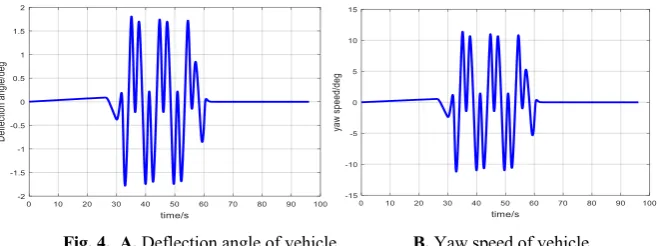
Deflection angle and yaw speed of vehicle were shown in Fig.4 A and B.
Fig. 4. A. Deflection angle of vehicle B. Yaw speed of vehicle
In Fig.4, the deflection angle, an important parameter to measure angular tracking error, was always within ±1.8o in whole serpentine test, which indicated that error of tracking angle was small. Fig.7showed that during entire serpentine simulation test, yaw speed was always controlled in range of 12deg/s, which indicated that vehicle stability was proper to avoid slipping or flicking possibilities in working conditions.
Based on self-tuning of immune feedback controller of BP network in the serpen-tine conditions, the performance index values were shown in Table 1.
Table 1. Performance index data
Method Error of tracking
Lateral accelera-tion
Steer-ing angle
Inclinational angle
Yaw speed
Nonlinear function ±0.15m, Max.±023 m ±0.42m/s2 ±70o ±2.6o ±12deg/s
Fuzzy Adjuster ±0.13m, Max.±0.20 m ±0.38m/s2 ±68o ±2.4o ±13deg/s
4.2 Evaluation of test result of carsim serpentine simulation
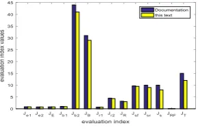
According to evaluation method of man-vehicle closed-loop maneuverability eval-uation index described in [22-23], indexes of serpentine simulation test were shown in Fig.5.
Fig. 5. evaluation index values
As could be seen from Fig.8, evaluation index values based on T and B cellular immune feedback controllers were less than those given in literature[24] (both for the serpentine condition), indicating that the controller had a good control effect. Howev-er, value of the evaluation index was greater than values of all other evaluation indicators, which resulted in a heavier load of the actuator, i.e., poor operational per-formance.
5
Model Experiment
The model vehicle was in the size of 1/8 of a real car; road width was 0.90m; ve-hicle width, 0.38m; and baseline, inner boundary of road. Entire field of view width was adjusted to 1.50m, with 80 evenly horizontal distributed pixels in a view range. In absence of obstacles, in course of straight and curved road tracking experiments the longitudinal speed of vehicle remained stable.
5.1 Test of tracking marking lines
During test, intelligent vehicle was parked at a position where there was no lateral distance deviation and angular deviation. The vehicle ran at test site at speeds of 1m/s, 1.25m/s and 1.5m/s, respectively for a circle. Lateral distance deviation between vehi-cle body and target road tracking along straight line and curve road was shown in Table 2.
Table 2. Lateral distance deviation of tracking straight line and tracking curve
Speeds Mean Value ( Line / Curve )cm value of lateral distance deviation( Line / Curve )cm
1.00 0.83/0.07 2.98/2.55
1.25 1.17/1.30 3.36/3.99
1.50 1.44/1.62 3.59/5.47
b2
From the Table, value of lateral distance deviation and mean value of lateral dis-tance deviation for both straight and curve paths tracking, with increase of speed, increased. When tracking a curve path, the time it took for steering system to adjust each time was longer than tracking straight path and the action frequency was faster. Thus, lateral distance deviation and mean value of lateral distance deviation for track-ing curve path were greater than that of straight path. The above experimental results show that design of experimental platform can better track straight path and curve path, with better robustness of vehicle speed and road curvature.
5.2 Obstacle avoidance
Obstacle avoidance tests were only carried out in straight road with obstacles of various sizes of pieces. The tests included two cases of avoiding small obstacles and large obstacles, with inner road boundary as comparative line. Starting point of vehi-cle was at road center. Initial direction was parallel to inner road boundary line. Di-mensions of two obstacles were 10cm x 5cm and 40cm x 23cm respectively. Obsta-cles were located on right side of left road boundary. Minimum speed of the intelli-gent vehicle was set at 1m/s, and maximum speed, at 1.6m/s with the first obstacle 1m from starting point. The distance between intelligent vehicle body center and left border of target road was to check obstacle avoidance position, as shown in Table 3.
Table 3. Location information of intelligent car during obstacle avoidance
Distance between the test point and the start
point R/m
The distance between central point of the smart car and left of the target lane d/cm
First time Second time Third time Fourth time
1 4.17 7.74 3.88 8.03
2 1.69 2.08 0.11 2.43
3 1.42 0.66 1.71 1.64
4 2.88 2.13 0.77 1.26
Data in Table 3 of vehicle location shows that intelligent vehicle in obstacle avoid-ance ran near centerline in the road without obstacles. In condition of road with obsta-cles, for obstacle from starting point of 1m, the vehicle changed direction and its body center position traveled away from the original travel path. Through tests of mark-tracking and obstacle avoidance of vehicle, the experimental results show that the experimental platform effectively realize tracking of marking line and avoidance of obstacles.
6
Conclusion
ap-results show that the approximation by BP network is better than that of fuzzy con-troller and radial symmetric nonlinear function. Carsim and Simulink were jointly used to experiment along serpentine road condition, and the comprehensive evaluation was carried out from the aspects of trajectory tracking error, manipulating burden, rollover and slip risk, and handling stability of control system. Experimental results also show that the algorithm effectively realizes tracking of intelligent vehicle mark and avoidance of obstacles.
7
References
[1]Lau H Y K, Wong V W K, Lee I S K. Immunity-based autonomous guided vehicles con-trol[J]. Applied Soft Computing, 2007, 7(1):41-57.
https://doi.org/10.1016/j.asoc.2005.02.003
[2]Wilburn B K. Fault-Tolerant Trajectory Tracking of Unmanned Aerial Vehicles Using Immunity-Based Model Reference Adaptive Control[J]. 2014.
[3]Nizami T K, Sundareshwaran K. A feedback control design of buck converter: An artificial immune system-based approach[C]Systems Conference. IEEE, 2016:1-6.
https://doi.org/10.1109/natsys.2015.7489101
[4]Lau H Y K, Wong V W K, Lee I S K. Immunity-based autonomous guided vehicles con-trol[M]Design and application of hybrid intelligent systems. IOS Press, 2003:41-57. [5]Lau H Y K, Wong V W K, Lee I S K. Immunity-based Autonomous Guided Vehicles
Con-trol.[C]Design and Application of Hybrid Intelligent Systems, His03, the Third Interna-tional Conference on Hybrid Intelligent Systems, Melbourne, Australia, December. DBLP, 2003:233-243.
[6]Navarro M, Caetano M, Bernardes G, et al. Automatic Generation of Chord Progressions with an Artificial Immune System[M] Evolutionary and Biologically Inspired Music, Sound, Art and Design. Springer International Publishing, 2015:175-186.
https://doi.org/10.1007/978-3-319-16498-4_16
[7]Tan Y. 1. Artificial Immune System[M] Artificial Immune System Applications in Com-putersecurity. John Wiley & Sons, Inc. 2016.
[8]Zhou Y, Tang S, Jia X, et al. Structural Damage Detection and Classification Algorithm Based on Artificial Immune Pattern Recognition[J]. Advanced Materials Research, 2014, 945-949(4):1265-1269. https://doi.org/10.4028/www.scientific.net/amr.945-949.1265
[9]Louati A, Darmoul S, Elkosantini S,et al. An artificial immune network to control inter-rupted flow at a signalized intersection[J]. Information Sciences, 2018, s 433–434:70-95.
https://doi.org/10.1016/j.ins.2017.12.033
[10]Alizadeh E, Meskin N, Khorasani K. A Dendritic Cell Immune System Inspired Scheme for Sensor Fault Detection and Isolation of Wind Turbines[J]. IEEE Transactions on Indus-trial Informatics, 2017, PP(99):1-1. https://doi.org/10.1109/tii.2017.2746761
[11]Xiao J, Li W, Liu B, et al. A novel multi-population coevolution strategy for single objec-tive immune optimization algorithm[J]. Neural Computing & Applications, 2016:1-14.
https://doi.org/10.1007/s00521-016-2507-1
[12]Vidal J M, Orozco A L S, Villalba L J G. Adaptive Artificial Immune Networks for Miti-gating DoS flooding Attacks[J]. Swarm & Evolutionary Computation, 2017, 38.
[13]Liu G, Yang L. Artificial immune controller for PMSM speed regulation system[C]//Bio-Inspired Computing: Theories and Applications (BIC-TA), 2010 IEEE Fifth International Conference on. IEEE, 2010: 582-585. https://doi.org/10.1109/bicta.2010.5645190
[14]Tan Y Z, Shen J, Zhen-Zhong L U. Study of Immune PID Controller for surperheated steam tenperature control system[J].Proceedings of the CSEE, 2002,22(10):148-152. [15]Wang N, Ren G. Study of ship boiler fuzzy immune self-adapting PID controller with
sys-tem simulation[J]. Journal of Dalian Maritime University, 2006, 37(1):1-4.
[16]Ren X Y, Feng-Shan D U, Huang H G, et al. Application of Improved Fuzzy Immune PID Controller to Bending Control System[J].Joural of Iron and Steel Research International. 2011, 18(3):28-33. https://doi.org/10.1016/s1006-706x(11)60033-2
[17]Liao X Z, Xiao Y L, Shuang L I. Fuzzy-Immune-PID Control in a Three-Phase PWM Rec-tifier[J]. Transactions of Beijing Institute of Technology, 2007, 27(12):1085-1089. [18]Mo hongwei,Principle and application of artificial immune system[M].HarBin institute of
technology press , 2002.
[19]Zhang B, Zhang W, Chen F, et al. Immune system multiobjective optimization algorithm for analysis of communication network planning[C] International Conference on Natural Computation. 2014:185-194. https://doi.org/10.1109/icnc.2014.6975863
[20]Zhang W, Yen G G, He Z. Constrained Optimization Via Artificial Immune System[J]. Cybernetics IEEE Transactions on, 2014, 44(2):185-198.
https://doi.org/10.1109/tcyb.2013.2250956
[21]Hagan, MartinT. Neural network design [M]. China Machine Press, 2002.
[22]Guo K,Chen M.Progress of the human-vehicle closed-loop system manoeuvrability’s eval-uation and optimization[J].Chinese Journal of Mechanical Engineering,2003,(10):27-35.
https://doi.org/10.3901/jme.2003.10.027
[23]Yang B, Sun Q H, Chen N, et al. Simulation research of handling stability of 4WS vehicle based on human-vehicle-road closed-loop system[J]. Journal of Machine Design, 2013. [24]Huang jianxing ,Zhao youqun.Comprehensive Evaluation of human-vehicle Closed-loop
System for Handling Stability and Technology of Virtual Prototype.[J] Journal of Me-chanical Engineering, 2010, (10): 102 -108. https://doi.org/10.3901/jme.2010.10.102
8
Acknowledgements
This work is partially supported by Scientific and Technological Project under Grant 20140311027-02. The authors also gratefully acknowledge the helpful com-ments and suggestions of the reviewers, which have improved the presentation.
9
Authors
Yanting Lan ([email protected]) is with North University of China School of Electrical and Control Engineering, Taiyuan, 030051, China.
Xiaodong Chen is with the College of Agronomy, China Agricultural University, Beijing 100193, China.