R E S E A R C H
Open Access
MIMO radar clutter mitigation based on joint
beamforming and joint domain localized
processing
Huiyong Li
†, Yongzhe Li
*†and Zishu He
Abstract
In this article, we propose a space–time adaptive processing scheme via a generalized sidelobe canceler (GSC) architecture for airborne multiple-input multiple-output (MIMO) radar. This scheme employs the waveforms
extracted by the matched filter bank that is cascaded at the receive end and utilizes digital beamforming technique to synthesize a certain number of transmit–receive beams, therefore, the operation of target detection in clutter environment can be conducted in all the directions of the formed beams in parallel. The GSC architecture is derived to implement adaptive reduced-rank (RR) clutter mitigation in a localized angle-Doppler space based on a novel RR multistage Wiener filter algorithm. The number of iterative stages in this algorithm is automatically selected in terms of a rank decision methodology. Meanwhile, beamforming and beam selecting methods are provided for this scheme, aiming at adaptively suppressing the clutter in localized domain. This scheme reverses the unavailability of the PA-efficient joint domain localized algorithm for MIMO radar. Moreover, it adapts to MIMO radar with arbitrary transmit–receive array space ratio. Even better, the proposed scheme has lower computation complexity than the traditional sample matrix inversion algorithm. The simulation results show that the proposed algorithm provide a signal-to-interference-plus-noise ratio improvement than traditional algorithms.
1. Introduction
Multiple-input multiple-output (MIMO) radar [1,2] has become an active area of radar research and application in recent years. The basic concept of MIMO radar is that there exists multiple radiating and receiving sites. In current literature, MIMO radar is divided into two basic types: one is referred to as statistical MIMO radar in which the transmit/receive array elements are broadly spaced, providing independent scattering responses for each antenna pair; the other is referred to as coherent MIMO radar in which the transmit/receive array ele-ments are closely spaced, assuming that the target is in the far field of the transmit–receive array. This article focuses on coherent MIMO radar and thus investigates the adaptive clutter mitigation performance.
As a key enabling technique, space–time adaptive pro-cessing (STAP) technique for PA has been motivated
for advanced airborne radar applications following the landmark publication by Brennan and Reed [3] and has reached a nearly mature height. In the past three de-cades, a large number of productive works have been done aiming at PA STAP [4-10]. It is well known that the essence of STAP is to adaptively adjust the two-dimensional space–time filter response to fully maximize output signal-to-interference-plus-noise ratio (SINR), and thus provide a better slow-moving target detection performance in strong clutter and jammer environment. The MIMO extension [2] of STAP has attracted increas-ing attention of researchers for MIMO STAP possesses the capability to assign transmit degrees of freedom (DOFs) into optimum processing including better clutter mitigation performance.
However, the MIMO STAP can be more challenging owing to the extra DOFs produced by orthogonal transmit-ted waveforms. Inevitably, the rank of clutter and jammer subspace will increase and the STAP of MIMO radar will be more complex. When full adaptive processing is implemented, large computational complexity caused by * Correspondence:[email protected]
†Equal contributors
School of Electronic Engineering, University of Electronic Science and Technology of China, Chengdu, Sichuan 611731, China
the matrix inversion operation and the challenging number of training samples will prevent the practical implementa-tion of STAP. This can be even more serious when the numbers of array elements and pulses in a coherent processing interval (CPI) are both large. Fortunately, reduced-dimension (RD) and reduced-rank (RR) STAP algorithms are able to relieve the heavy computational burden for MIMO radar while maintaining good perform-ance. The key objective of RD/RR STAP is to reduce com-putational cost and thus improve statistical convergence. RD STAP cut back the adaptive DOFs physically by trans-formation that is data independent [6]; while RR STAP projects the received data into a lower dimensional subspace spanned by a set of basis vectors utilizing a data-dependent transformation.
Multipath clutter mitigation for MIMO STAP radar can be found in [11]. In [12], the MIMO radar clutter subspace was reconstructed with orthogonal prolate spheroidal wave function by fully utilizing the geometry of MIMO radar. Although it has lower computational complexity and formulates the data-independent clutter rank, it indeed depends too much on the ideal case and is not robust to the clutter mismatch. Current studies on MIMO STAP mainly focus on RR STAP [12-15]. In [13], a recursive least squares implementation is employed to calculate the transformation matrix and adaptive coeffi-cients. In [14], clutter rank estimation was investigated with waveform diversity and it was derived that the clutter covariance matrix could be a function of waveform covari-ance matrix.
In this article, we develop a new STAP scheme with a generalized sidelobe canceler (GSC) architecture. A RR multistage Wiener filter (MWF)-based algorithm is de-rived for this architecture, aiming at significantly reducing the computational burden of MIMO STAP. First, we ex-ploit all the signals extracted by the matched filter (MF) bank to form a certain number of joint transmit–receive beams; Then the receiving data are projected into angle-Doppler domain, therefore, clutter mitigation and target detection can be conducted in all the directions of the synthesized beams in parallel. This scheme has reversed the impracticability of the noted JDL algorithm when applied to MIMO radar, and adapts to MIMO radar with arbitrary ratio of transmit and receive element space.
This article is organized as follows. In Section 2, we formulate the generalized signal model of airborne MIMO radar with a sidelooking array configuration that is allowed to separate into subarrays. In Section 3, the beamforming-based modified joint domain localized (BBM-JDL) STAP scheme with a GSC architecture is proposed. The computation efficient RR MWF algorithm is derived in this section followed by the formulation of an AMF CFAR detector. Furthermore, the beamforming and beam selecting methods are proposed in this article,
which are capable of promoting the performance of MIMO STAP. Some examples illustrating the compa-rative SINR performances of MIMO and PA radar are presented in Section 4. Finally, the conclusion is given in Section 5.
2. Signal model and problem statement
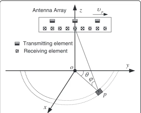
In this section, we consider a pulsed Doppler radar resid-ing on an airborne platform. The geometry of the chosen coordinate system is illustrated in Figure 1, in which it is assumed that the airborne platform flies along positivey -direction at a speed ofυP. The platform is assumed to lo-cate over the x–y plane with a height of h. As shown in Figure 1, a sidelooking uniform linear array configuration
is employed for transmitter and receiver. There are M
transmitting elements with uniform space dTand N
re-ceiving elements with uniform spacedR. The transmit and receive arrays are both linear and parallel, and each one contains a group of omnidirectional elements.
Conse-quently, they share the same azimuth θ and elevation
angleϕ. The transmitting array is evenly partitioned into
Ksubarrays that are allowed to overlap. In this article, we also assume that the transmitting waveforms meet the
narrow-band condition. We assume thatλ be the
operat-ing wavelength,Tr be the pulse repetition interval (PRI), and one CPI consists of L pulses. Let ―sk ∈CNS1; k¼ 1;2;…;K, be theNs-length discrete version of the
com-plex baseband waveform at thekth transmitting subarray
in each PRI. Mutually orthogonal or non-coherent wave-forms are employed at the transmitting end for MIMO radar while identical ones for PA. Thus, the signal matrix can be denoted as ―S¼―s1 ―s2 … ―sK∈CNSK. In order to guarantee a fair comparison, we define the auto-correlation of each column in ―S to be unitary. Thus, the
x
y z
o Antenna Array
Transmitting element Receiving element
p
p
output signal matrix of thekth subarray can be expressed
which means that the total transmit energy of the kth
subarray is equal to M/K. ―wk is a P × 1 unit-norm
beamforming weight vector, and P is the number of
elements in each subarray. The notation (·)H means the
operation of conjugate transpose. Therefore, the echoes reflected from an iso-range ring for thelth pulse can be il-lustrated as cosθcosϕTr/λdenotes the normalized Doppler frequency.
ψT= 2πPdTcosθcosϕ/λis the phase shift induced by the distance between adjacent subarrays which means that the distance between any two neighbor transmit phase centers is P times that of dT.aR(θ) is the N× 1 receive steering by the distance of the receiving element. Note that for a fixed iso-range ring, the elevation angle is a definite
quan-tity. The notation (·)T means the operation of matrix
transpose.ak(θ) is the steering vector of thekth subarray. A way of simplifying the analysis is to selectak(θ) as We define the transmit steering vectoraT(θ) as
aTð Þ ¼θ 1;ejψT;…;ej Kð 1ÞψT
h iT
∈CK1: ð5Þ
Define the coherent processing gain of theKsubarrays as
Chð Þ ¼θ ―wH1a1ð Þθ … ―w
H KaKð Þθ
h iT
∈CK1: ð6Þ
By dividing the iso-range ring intoNcclutter patches in the cross-range direction, Equation (2) can be expressed in discrete form as
yl¼ in which θi denotes the azimuth of the ith clutter patch. MF bank should be employed at the receivers in order to
get sufficient statistics. Hence, the clutter echoes for the
lth pulse can be compressed by the matched signal matrix ―
S . By stacking the compressed data into a columnwise vector with lengthKN× 1, we get the expression ofclas
denoted in Equation (8) where R―
S¼ ―SH―S
and the nota-tion Vec(·) means the stacking operanota-tion.
cl ¼Vec―SHyl∈CKN1
After stackingclfor all the pulses, we obtain the matrix C¼½c1;c2;…;cL∈CKNLas the clutter data, i.e.,
Thus, Equation (9) can be denoted as
C¼XNc
Similarly, the echo data of the target located in the dir-ection ofθtcan be modeled as
where β(θt) denotes the reflected coefficient of the
target.
An important task that should be well fulfilled for air-borne radar system is target detection. The detection problem can be casted in the context of binary hypoth-esis test. We can denote the signal-absence hypothhypoth-esis byH0and the signal-presence hypothesis byH1, i.e.,
H0:x¼xu
H1:x¼xtþxu; ð14Þ
where xt= Vec(Xt) represents the potential target
undesired interference or noise component including clutterxc, jammingxj, and thermal noisexn, i.e.,
xu¼xcþxjþxn; ð15Þ
where xc = Vec(C) represents the clutter component.
We assume that the components of xu are mutually
uncorrelated. Thus, the interference covariance matrix Rucan be expressed as
Ru¼Ε xuxHu
¼RcþRjþRn: ð16Þ
whereRc¼Ε xcxH c
,Rj¼Ε xjxHj
n o
;andRn¼Ε xnxH n
,
denote clutter, jammer, and thermal noise covariance matrix, respectively. Ε{·} means the expected value of a random quantity. For convenience, Equation (14) can be rewritten in the following matrix form
H0:X¼Xu
H1:X¼XtþXu; ð17Þ
where Xu = C + J + N denotes the matrix form of xu
which contains clutter C, jammingJ, and noise
compo-nentNin matrix form. It should be noted that the dimen-sion ofX,J, andNare the same as that ofC.
3. RR BBM-JDL STAP with GSC architecture
The JDL-GLR algorithm proposed by Wang and Cai [6] is much more data efficient in the sense of fast convergence and requires fewer training data samples than other suboptimum STAP algorithms. This algorithm demon-strates constant false alarm rate characteristic and strong robustness. Straightforward application of JDL-GLR algo-rithm is no longer valid for MIMO radar. JDL algoalgo-rithm transforms the receiving dataset to angle-Doppler domain by a two-dimensional discrete Fourier transform (DFT), which is efficient for PA radar because the spatial phase of PA radar is a uniform and linear growth process. However, the spatial phase of MIMO radar is neither uniform nor linear, especially when it does not meet the virtual array case. When FFT is operated to the receiving dataset of MIMO radar, it fails to transform to beam space.
Joint transmit–receive beamforming can be a suitable
way to settle the above-mentioned problem. We have extended our work [16] in this article. In this section, we propose the BBM-JDL STAP scheme with a classical
GSC architecture. The joint transmit–receive digital
beamforming-based STAP scheme is illustrated in Section 3.1. Section 3.2 derives the computation efficient RR MWF algorithm and formulates an AMF CFAR de-tector for this JDL scheme. The beamforming and beam selecting methods as well as some relevant analysis are provided in Section 3.3. We form a certain number of
joint transmit–receive beams in the direction of radar
search area, and then project the receiving data into
angle-Doppler domain by a Fourier transform. After that the joint domain STAP and adaptive MF (AMF) CFAR test can be accomplished utilizing a GSC archi-tecture. In contrast to the work in [9], which formulates the AMF CFAR test with an MWF structure and needs to construct blocking matrix when calculating the weighted value, we employ a simpler RR MWF algo-rithm with lattice structure. Target detection can be carried out in all the direction of the formed joint beams simultaneously.
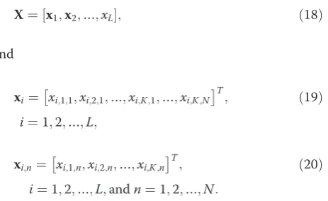
3.1. BBM-JDL STAP scheme
Figure 2 illustrates the processing procedure of the pro-posed BBM-JDL STAP processor. This scheme belongs to an RD-RR category. First, the operation of joint trans-mit–receive beam forming is performed utilizing the
re-ceiving data matrix X, whose columns represent KN
extracted signals for different pulses in one CPI. Let
X¼½x1;x2;…;xL; ð18Þ
and
xi¼ xi;1;1;xi;2;1;…;xi;K;1;…;xi;K;N
T;
i¼1;2;…;L;
ð19Þ
xi;n¼ xi;1;n;xi;2;n;…;xi;K;n
T;
i¼1;2;…;L;andn¼1;2;…;N:
ð20Þ
Thus, at the first step, we can form beams with the matched signals at the end of each receiving element. This process is referred to as transmit beamforming, which can be expressed as
exi;n;b¼xHi;naTð Þθb i¼1;2;…;L;
n¼1;2;…;Nandb¼1;2;…;NB;
ð21Þ
where aT(θb) is expressed in Equation (5), θbis the
azi-muth of thebth desired beam, and NBis the number of
beams to be synthesized in the direction of the coverage
area. Note that ψT in (5) actually is a function of
azimuth θ and elevation angleϕ. However, the value of
elevation angle ϕ varies in different range bins.
Conse-quently, it is not convenient to calculate this varying quantity when implementing beamforming. Considering that the elevation angles of the rang bins that are
adja-cent to the rang cell under test change slowly, thus ϕ
Let
exi;b¼ exi;1;b;xei;2;b;…;exi;N;b
T
i¼1;2;…;L:;
b¼1;2;…;NB:
ð22Þ
At the second step, we formNBreceiving beams with
e
xi;b, b= 1, 2,…, NB. This operation is referred to as re-ceive beam forming, which can be described as
eexi;b¼exHi;baRð Þθb i¼1;2;…;L:;b¼1;2;…;NB: ð23Þ
This process is very similar to that of transmit beam-forming. Thus, we can merge these two beamforming process into a joint one that can be demonstrated as
eexi;b¼xHi ðaRð Þθb ⊗aTð Þθb Þi¼1;2;…;L:;
b¼1;2;…;NB:
ð24Þ
Define spatial frequencyfsas fs=dRcosθcosϕ/λ, thus aR(θ) can be replaced byaR(fs), whereaR(fs) is denoted as
aRð Þ ¼fs 1;ej2πfs;…;ej2πðN1Þfs
h iT
∈CN1: ð25Þ
Hence, we can rewrite Equation (24) as
eexi;b¼xHi ðaRð Þfs ⊗aTð Þγfs Þi¼1;2;…;L:;b
¼1;2;…;NB: ð26Þ
where γ =PdT/dR. Note that Equation (26) provides an efficient approach to implement joint beamforming for
airborne MIMO radar with arbitrary transmit–receive
array space ratio. We can ignore the influence ofϕonfs by replacing fs with fs0 = dR cos θ/λ when completing clutter mitigation and target detection in the direction
of the coverage area. Obviously, the beam-formed data matrix can be denoted as
ee
X¼ eex1;1⋯eex1;NB;eex2;1⋯eex2;NB;…eexL;1⋯eexL;NB
h i
ð27Þ
Second, a DFT is applied to each column of the
beam-formed data matrix Xee, which transforms the receiving
data to Doppler domain.
Next, we follow the idea of JDL [6] to form a group of localized processing regions (LPRs) on the purpose of reducing the dimension of the receiving data matrix physically. Figure 3 illustrates the schematic diagram of LPRs. This scheme makes us to concentrate our atten-tion on a small fracatten-tion of all the processing regions. #
1
MF 1# MF M#
#
N
MF 1# MF M# Receiving data matrix
Transmit-receive digital beam forming
B
N L
X
D F T D
F T
D F T
D F T
Angle-Doppler space data matrix
B
N L
X
AMF 1# AMF L#
Data of adjacent cells
KN L X
1 Nb Nl
Output b l
N N
L
Transmit
Receive T
a
R a
Figure 2Block diagram of BBM-JDL STAP processor for MIMO radar.
Unlike [6], MIMO radar transmits low-gain wide beams because of the orthogonality of transmitting signals which cannot be stacked in homo-phase to synthesis high-gain narrow beams. Consequently, it is sensible to form multi-beams with high gain at the end of the receiver. The multi-beams cover the whole area where the wide trans-mitting beams reaches. It is necessary to search in both
the Doppler domain and the joint transmit–receive beam
domain when detecting targets. Obviously, we can finish searching in the valid detectable area for few times.
It should also be pointed out that the calculated amount of data processing in the LPR is much less than that of processing the entire receiving data matrix. Even though varieties of RD transformations can be applied to, the LPR processing is more superior for the size of LPR can be very small.
3.2. RR MWF algorithm and AMF CFAR detector
Figure 4 illustrates a GSC structure which is applied to the LPR depicted in Figure 3.
Let xLPR(n), n = 1, 2,… ,K be the data matrix of the LPR, and assume the size ofxLPR(n) isNt×Ns. Then we can filter out the desired signald0(n),n= 1, 2,…,Kand the input data vector x0(n), n= 1, 2,…,K from xLPR(n) by the steering vector s0and transformation matrixT0, respectively. Kis the data length. All the elements ofs0 are equal to zero except the one being detected equal to 1, and all the elements of T0are also equal to zero ex-cept the ones at the principal diagonal and the
second-ary diagonal. Assume the ith bin in the LPR is being
detected, we can formulate s0and T0in Equations (28)
and (29) where Ii–1 is a i – 1-dimensional identity
matrix.
s0¼ |fflfflfflfflfflfflffl{zfflfflfflfflfflfflffl}0 ⋯ 0 i1
2 6
4 1 0 ⋯ 0
|fflfflfflfflfflfflffl{zfflfflfflfflfflfflffl} NtNsi
#
Tð28Þ
T0¼
Ii1
0 INtNsi 0
2 4
3
5 ð29Þ
Figure 5 shows the structure of the computation effi-cient MWF that is used to calculate the weighted value
WGSC. This scheme entails block-oriented processing
[8], but it avoids computation of blocking matrices and covariance matrix (for which there may not be sufficient sample support). To obtain stronger robustness and bet-ter performance, we modify this MWF structure to con-tainDiterative steps which is truncated at stageDwhen the norm of the previous error signals εD−1(n) is lower than the given threshold. The iterative processing steps are showed in Table 1.
This scheme follows the idea of iterative correlating-subtracting, i.e., at each step, the correlated component is subtracted from the desired signals. The desired signal is updated by the remaining component after subtracting.
It should be noted that the adaptive stopping stageD
should be larger than the rank of the clutter in the current detecting LPR. When the size of LPR is selected,
we can choose D adaptively according to the fixed
threshold and the estimated rank of the clutter in the LPR.
The AMF CFAR detector expressed in a GSC form is demonstrated in [9]. As depicted in Figure 4, the corre-sponding error signals can be expressed as
ε0ð Þ ¼n sHWGSCH T0
VecðxLPRð Þn Þ ð30Þ
Thus, the associate MMSE for GSC can be denoted as
ψ0¼σ2d0r
H
x0d0R 1
x0rx0d0: ð31Þ
The AMF CFAR test can be expressed as
Λ¼ sHWGSCH T0
VecxLPR
n
2
σ2
d0r
H
x0d0R 1
x0rx0d0
¼jε0ð Þn j2 ψ0
><
H1
H0 η;
ð32Þ
where the threshold η is derived from the false alarm
probabilityPFAas denoted as
PFA¼Qð1;ηÞ ¼eη; ð33Þ
in whichQ(·) is the incomplete gamma function.
By replacing WGSC in (32) with wð Þ0D illustrated in
Table 1, we can derive the RR MWF-based AMF CFAR as
Λ¼ s
3.3. Beamforming and beam selecting strategy
PA radar transmits identical waveforms at each transmit element, and these waveforms are reflected by the target located in far field with linear phase difference. Indeed, these echoes are superposed when they are received at the end of the receiving end. Utilizing the coherency of the reflecting echoes, a narrow and high-gain beam is formed when beamforming technique is applied. How-ever, MIMO radar does not work that way. For the MIMO case, mutually orthogonal or non-coherent wave-forms that cannot be stacked in homo-phase are transmit-ted, thus only wide low-gain beams can be synthesized at the transmitting end. In order to cover the whole area that the wide transmitting beams illuminate, multiple beams should be formed at the receiving end.
However, the problems with this technique are that how many beams should be formed in the direction of the illuminated area for MIMO radar, and how should the synthesized beams be selected by the RR GSC archi-tecture. For an airborne radar system with fixed config-uration, the main lobe beam width of each synthesized beam is a fixed quantity (no windows) or larger than this
fixed value (with windows). Thus, if there is no con-straints on the number of beams, they will be seriously overlapped, leading to a strong correlation between the main and auxiliary beams. Moreover, large number of beams means that the frequency difference between neighbor beams exceeds the frequency resolution which is determined by the dimension of the spatial and tem-poral data. Consequently, when these overlapping beams are applied to the RR GSC architecture, perfect cancel-ation between the main beam and auxiliary beams will not be obtained because of failing to estimate an accur-ate clutter subspace.
In order to achieve good performance of the RR GSC processing scheme, the following conditions should be considered:
(i) The number of the synthesized beams should be selected according to the dimension of the spatial and temporal data, in order to maintain the orthogonality of canceling beams.
(ii) The beams that are adjacent to the main lobe should be selected, including the spatial and Doppler domains. More adjacent main lobe beams will achieve a good estimation of the clutter subspace in the joint domain.
(iii) The position of the selected beams can be selected in a random form, on condition that the
calculation load is acceptable.
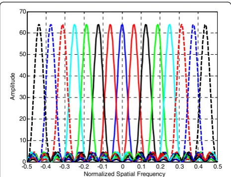
Figure 6 shows the synthesized multiple beam pattern utilizing sixteen transmit/receive elements (four uniform non-overlapped subarrays for transmitting). Assuming that the frequency has been normalized, thus we can only
Figure 5Computation efficient RR MWF with lattice structure.
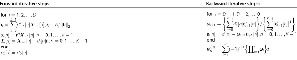
Table 1 Recursion steps for RR MWF algorithm
Forward iterative steps: Backward iterative steps:
synthesize 15 orthogonal beams in the range of all direc-tion. However, if the potential target is present in the dir-ection between two neighbor beams in Figure 6, performance loss will occur because the main lobe of the synthesized beam is not at the direction of the target. An acceptable solution is to implement the same beam-forming technique in the direction that is not illuminated, only to guarantee the performance loss that is less than 3 dB. Target detection can be conducted in the joint domain by selecting different canceling beams.
Note that one important aspect to fix attention is the differences in the noise power. The noise power after
matched filtering for MIMO radar isKtimes that of PA
which results that the signal-to-noise ratio (SNR) of PA
isKtimes that of MIMO radar. To make up for this loss,
MIMO radar should possess K times integration time
than PA in order to guarantee a same force.
3.4. MIMO radar STAP
In this section, we formulate the MIMO STAP problem. The goal of MIMO STAP is to maximize the SINR by combining the extracted signals separated by MFs so as to improve the slow-moving target detection perform-ance eventually.
For the BBM-JDL scheme, assuming that the transmit antennas are well illuminating the direction of target and all elements of Chare equal. The size of the LPR is selected to beNb×Nlwhich meansNlDoppler bins and
Nbbeams are contained in the lth LPR. Thus, the STAP
based on the linearly constrained minimum variance cri-terion can be formulated as
minwwHRlw
s:t:wHVec Slt ¼1;
ð35Þ
where w is the weighted value, and Slt is the target
steering matrix in angle-Doppler domain that has all its entries equal to zero except the target-mapping one which is LKN for the lth LPR. Rl ≜ Ε[Vec(χl)VecH(χl)]
with Ε[·] denoting the expectation and it can be
esti-mated by the samples from the NRneighbor range bins,
i.e.,
The optimal solution to (35) with matrix inversion can be denoted by
Thus, we can calculate the output SINR performance of thelth LPR denoted by
In this section, we assess the proposed RD-RR STAP scheme utilizing simulated data. The parameters of the airborne radar platform are shown in Table 2. It is assumed that the receiving noise after matched filtering is Gaussian white noise whose power is calculated according to thermal noise. Constant gamma reflection coefficient model is employed when calculating the clut-ter of the airborne radar system.
In the first experiment, we evaluate the SINR perform-ance of PA and MIMO radar utilizing the proposed RR STAP. We divide the transmitting array into four subarrays which are 16 × 16 planar arrays for MIMO radar, and each subarray transmits an orthogonal wave-form. For PA radar, there is no need to partition the transmitting array. The pulse number of PA is selected for MIMO radar to be 64, thus in order to maintain a fair comparison between PA and MIMO radar, 256 pulses should be selected for MIMO radar. The range of interest is 100 km, and the maximum operating range of the radar system is assumed to be 400 km. In this sce-nario, the range ambiguity is considered, and 100 range cells are employed when estimating the clutter covari-ance in each LPR. We also assume that channel mis-match is present with 5% amplitude error and 5° phase error. The amplitude error is assumed to be Gaussian distributed and the phase error is assumed to be uni-formly distributed. The RCS of the potential target is
as-sumed to be 5 m2. To obtain a performance comparison
of PA and MIMO radar with this proposed RR GSC -0.50 -0.4 -0.3 -0.2 -0.1 0 0.1 0.2 0.3 0.4 0.5
scheme, we choose the size of the LPR to be 3 × 3 for both systems.
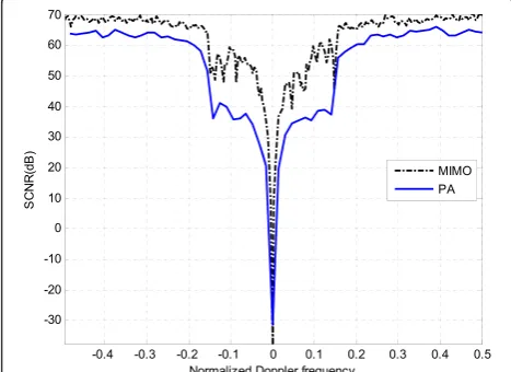
Figure 7 shows the output SINR performance of PA and MIMO radar in the abovementioned scenario. As depicted in Figure 7, the clutter is mainly located in the
range of normalized Doppler frequency between −0.15
and 0.15, thus the output SINR performance of the high normalized Doppler frequency area is expected to reach to output SNR performance. However, because of the present channel mismatch, performance loss will occur in this scenario. This simulation result also shows that MIMO radar can achieve a higher SINR performance than PA radar in the context of channel mismatch. The reason of this result is that MIMO radar possesses more adaptive DOFs, which will fully process the clutter and noise component, even when the clutter environment is deteriorated. For PA radar, there are limited adaptive DOFs, resulting that the deteriorated clutter cannot be fully suppressed. It should be noted that in the main lobe clutter area, MIMO radar has shown obvious super-iority for slow-moving target detection. MIMO radar
can achieve a higher resolution than PA due to its long integration time.
In the second experiment, we use the same parameters for MIMO radar system as the first experiment. We assess the performance of the proposed RR GSC pro-cessing scheme by comparing with traditional JDL method. Considering that the JDL algorithm employs matrix inversion when calculating the adaptive weights, heavy computation load will cost for JDL. While for the proposed RR GSC scheme, we only need limit steps of iteration to calculate the RR weights without perform-ance loss. Thus, we can use a larger selected LPR size with 5 × 5 or 7 × 7 to maintain a calculation load which is close to JDL with 3 × 3. We do not provide a detailed computation burden comparison in this article. In fact, the computational amount of our proposed scheme with larger size is approximately in the same level of that for JDL with smaller size. As depicted in Figure 8, the
pro-posed RR GSC scheme can achieve a 2–4-dB
perform-ance improvement than the traditional JDL with 3 × 3 LPR. This provides approach for us when large receive data size is to be processed.
5. Conclusion
In this article, we devote ourselves to solving the invalid-ity problem of JDL algorithm when applied to MIMO STAP radar, and we have proposed an RR GSC process-ing scheme which makes full use of the extracted signals
and forms some number of joint transmit–receive beams
instead of implementing Fourier transformation. This scheme adapts to MIMO radar with arbitrary space ratio between transmitter and receiver elements. A GSC structure is used to detect target by employing an RR MWF algorithm. We have provided the beams selecting strategy for MIMO radar system with analysis and com-parison with PA radar. Simulation results show that this Table 2 Radar system parameters
Parameter Value
Antenna array Side-looking planar array
(64 × 16)
Transmitting antenna array element space 0.125 m
Receiving antenna array element space 0.125 m
Operating wavelength 0.25 m
Pulse repetition frequency 8000 Hz
Platform velocity 150 m/s
Height of platform 10 km
Transmit peak power per element per pulse 500 w
Target azimuth 0°
Figure 7Output SINR performance of PA and MIMO radar for experiment 1.
scheme is valid for MIMO STAP radar by comparing the performances of PA and MIMO radar. It is also shown that, under the closely computation load condi-tion, the proposed RR GSC scheme possesses superiority than the traditional JDL.
Competing interests
The authors declare that they have no competing interests.
Acknowledgement
The authors Yongzhe Li and Huiyong Li are the co-first authors, and they contributed equally to this study. Yongzhe Li was supported by the Fundamental Research Funds for the Central Universities of China under Contract number ZYGX2010YB007, and by China Scholarship Council. Huiyong Li was supported by the China Postdoctoral Science Foundation under Contract number 2012M520077, and by the Fundamental Research Funds for the Central Universities of China under Contract number ZYGX2012J018.
Received: 2 December 2012 Accepted: 3 March 2013 Published: 8 April 2013
References
1. E Fishler, A Haimovich, RS Blum, D Chizhik, LJ Cimini, RA Valenzuela, MIMO radar: an idea whose time has come. Proceedings of the IEEE Radar Conference, 71–78 (2004)
2. DW Bliss, KW Forsythe, Multiple-input multiple-output (MIMO) radar and imaging: degrees of freedom and resolution. Proceedings of the 37th IEEE Asilomar Conference on Signals, Systems, Computers1, 54–59 (November 2003) 3. LE Brennan, IS Reed, Theory of adaptive radar. IEEE Trans. Aerosp. Electron.
Syst.AES-9(2), 237–252 (1973)
4. IS Reed, JD Mallett, LE Brennan, Rapid convergence rate in adaptive arrays. IEEE Trans. Aerosp. Electron. Syst.AES-10(6), 853–863 (1974)
5. AM Haimovich, Y Bar-Ness, An eigenanalysis interference canceller. IEEE Trans. Signal Process.39(1), 76–84 (1991)
6. H Wang, L Cai, On adaptive spatial-temporal processing for airborne radar systems. IEEE Trans. Aerosp. Electron. Syst.30(3), 660–670 (1994) 7. JS Goldstein, IS Reed, Reduced-rank adaptive filtering. IEEE Trans. Signal
Process.45(2), 492–496 (1997)
8. JS Goldstein, IS Reed, LL Scharf, A multistage representation of the wiener filter based on orthogonal projections. IEEE Trans. Inf. Theory
44(7), 2943–2995 (1998)
9. JS Goldstein, IS Reed, PA Zulch, Multistage partially adaptive STAP CFAR detection algorithm. IEEE Trans. Aerosp. Electron. Syst.35(2), 645–661 (1999) 10. WL Melvin, A STAP overview. IEEE Aerosp. Electron. Syst. Mag.19(1),
19–35 (2004)
11. VF Mecca, D Ramakrishnan, JL Krolik, MIMO radar space–time adaptive processing for multipath clutter mitigation. Proceedings of the IEEE Workshop Sensor Array Multichannel Signal Processing, 249–253 (2006) 12. C-Y Chen, PP Vaidyanathan, MIMO radar Space–time adaptive processing
using prolate spheroidal wave functions. IEEE Trans. Signal Process.
56(2), 623–635 (2008)
13. R Fa, RC de Lamare, P Clarke, Reduced-rank STAP for MIMO radar based on joint iterative optimization of knowledge-aided adaptive filters. Conference Record of the Forty-Third Asilomar Conference on Signals, Systems, and Computers (2009)
14. GH Wang, YL Lu, Clutter rank of STAP in MIMO radar with waveform diversity. IEEE Trans. Signal Process.58(2), 938–943 (2010)
15. VF Mecca, JL Krolik, MIMO enabled multipath clutter rank estimation. IEEE Radar Conference (2009)
16. YZ Li, ZS He, HM Liu, J Li, A new STAP method for MIMO radar based on joint digital beam forming and joint domain localized processing. CIE International Conference on RadarII, 1107–1110 (2011)
doi:10.1186/1687-1499-2013-99
Cite this article as:Liet al.:MIMO radar clutter mitigation based on joint beamforming and joint domain localized processing.EURASIP Journal on Wireless Communications and Networking20132013:99.
Submit your manuscript to a
journal and benefi t from:
7 Convenient online submission 7 Rigorous peer review
7 Immediate publication on acceptance 7 Open access: articles freely available online 7 High visibility within the fi eld
7 Retaining the copyright to your article