R E S E A R C H
Open Access
Vector bin-and-cancel for MIMO
distributed full-duplex
Jingwen Bai
*and Ashutosh Sabharwal
Abstract
In a multi-input multi-output (MIMO) full-duplex network, where an in-band full-duplex infrastructure node communicates with two half-duplex mobiles supporting simultaneous up- and downlink flows, the inter-mobile interference between the up- and downlink mobiles limits the system performance. We study the impact of leveraging an out-of-band side channel between mobiles in such network under different channel models. For time-invariant channels, we aim to characterize the generalized degrees-of-freedom (GDoF) of the side-channel-assisted MIMO full-duplex network. For slow-fading channels, we focus on the diversity-multiplexing tradeoff (DMT) of the system with various assumptions as to the availability of channel state information at the transmitter (CSIT). The key to the optimal performance is a vector bin-and-cancel strategy leveraging Han-Kobayashi message splitting, which is shown to achieve the system capacity region to within a constant bit. We quantify how the side channel improve the GDoF and DMT compared to a system without the extra orthogonal spectrum. The insights gained from our analysis reveal (i) the tradeoff between spatial resources from multiple antennas at different nodes and spectral resources of the side channel and (ii) the interplay between the channel uncertainty at the transmitter and use of the side channel.
1 Introduction
Increasingly, mobile devices have multiple radios to simul-taneously access different parts of the spectrum, e.g., cellular and ISM bands. The ability of simultaneous access to multiple parts of the spectrum provides an opportunity to use multiple bands in new and unique ways. A common method is to use the two bands to access both cellu-lar and ISM band networks (notably WiFi) at the same time, which is now an integral part of cellular provider data strategy to offload cellular traffic to WiFi networks [1]. In this paper, we will consider the use of device-to-device (D2D) wireless channels between mobile device-to-devices, to serve as side channels toaidmain-channel communica-tion with the infrastructure nodes. For example, the main network could be on a cellular band while the wireless side channel could be on an unlicensed ISM band. The con-ventional use of D2D involves establishing peer-to-peer communication [2], forming virtual MIMO by coopera-tive communication [3] or offloading cellular traffic [4]. In contrast, we propose to use the D2D side channel for interference management to improve the cellular capacity,
*Correspondence: [email protected]
Department of Electrical and Computer Engineering, Rice University, Houston, USA
a scenario which we labeled asISM-in-cellular communi-cation [5–7].
In this paper, we will study how the side channel will impact the system performance in a two-user MIMO full-duplex network. In-band full-full-duplex operation promises to double the spectral efficiency as compared to the half-duplex counterpart which uses either time division or frequency division for transmission and reception. It is in fact feasible to design near-perfect full-duplex base stations owing to the available freedom (bigger size, non-battery-powered operation) in their designs (e.g., see [8–10] and the references therein). And in-band full-duplex has already become part of the ongoing standard both in 3GPP [11] and 802.11-ax [12]. Thus, we envi-sion that the first use of full-duplex capabilities might be in a small cell infrastructure [13], supporting legacy half-duplex mobile nodes.
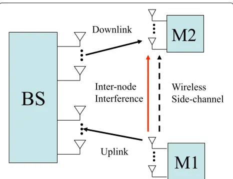
In Fig. 1, a full-duplex-capable base station (BS) com-municates with two half-duplex mobiles simultaneously to support one uplink (UL) and one downlink (DL) flow. A major bottleneck in this network is the inter-mobile interference from uplink mobile (node M1) to downlink mobile node (node M2), because of which the degrees-of-freedom of the network collapse to one when all nodes
Fig. 1MIMO full-duplex network: inter-mobile interference becomes an important factor when the full-duplex infrastructure node communicates with uplink and downlink mobile nodes simultaneously
are equipped with single antenna (SISO) [6]. As a result, we proposed a distributed full-duplex architecture [6] to leverage the wireless side channels to mitigate inter-mobile interference. In the case of MIMO scenario which has been widely studied for half-duplex system [14], one driving question for distributed full-duplex system is if and how the spatial degree-of-freedom, i.e., number of antennas at the base station and mobiles, will be corre-lated to the spectral degrees-of-freedom offered by the side channel.
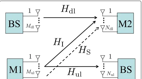
In our setup, we assume that uplink node M1 hasMul transmit antennas, the downlink node M2 hasNdlreceive antennas, the full-duplex BS has Mdl and Nul transmit and receive antennas, respectively. The bandwidth of the side channel between the mobiles isW-fold compared to the main-channel. We summarize the main results in this work as follows.
1. In the time-invariant channels, we obtain the capacity region to within a constant bit achieved by a vector bin-and-cancel scheme. We also analyze the role of channel uncertainty at the transmitter and characterize theGDoFas a function of antenna numbers and side-channel bandwidth under different assumptions of CSIT. The insights gained fromGDoFreveal the tradeoff between spatial resources from multiple antennas and spectral resources of the side channels as well as the interplay between the channel uncertainty at the transmitter and the use of side channel. In the case when BS has more antennas than mobiles, if there are more downlink receive antennas than uplink transmit
antennas, i.e.,Ndl≥Mul, there is no benefit to obtain
CSIT since with and without CSIT achieve the same degrees-of-freedom. On the other hand, ifMul>Ndl,
having CSIT require less side-channel bandwidth to achieve no-interference performance. Thus, we conclude that having more spatial degree-of-freedom at the interfered downlink receiver or larger
side-channel bandwidth can simplify transceiver design by ruling out the necessity to obtain CSIT. 2. In slow-fading channels, we derive the general DMT
regarding different assumptions of CSIT. Specifically, we quantify the bandwidth of the side channel required to compensate forlack of CSIT such that the DMT without CSIT achieves the optimal DMT with CSIT. Interestingly, in the case when
Mdl=Nul=M≥Mul,Ndl, the required bandwidth is inversely proportional to the number of antennas at the BS, i.e.,W ∝ M1. The caveat is that the
side-channel channel SNR, in the meantime, has to grow with the number of antennas at BS. The result provides guidance towards system design; larger number of BS antennas, e.g., recent discussions on massive MIMO [15], can help reduce the required side-channel bandwidth to combat inter-mobile interference.
We also observe the dependency of CSIT and the antenna number ratio between the mobiles. For the symmetric DMT, whenMul>Ndl, without side channel, the lack of CSIT will result in performance loss. However, larger side-channel bandwidth will help bridge the performance gap. On the other hand, whenNdl≥Mul, there is no benefit to obtain CSIT to
achieve no-interference DMT since, with and without CSIT, one requires the same amount of side-channel bandwidth to completely eliminate the effect of interference. Hence, in the protocol design, the scheduler could possibly group downlink user with more receive antennas to eliminate the overhead of acquiring CSIT.
3. We evaluate the required side-channel bandwidth to
achieve the no-interferenceGDoFand DMT under
different channel models such that the effect of inter-mobile interference can be completely eliminated via side channel. The key difference in the findings between the two channel scenarios, for instance, whenMdl=Nul=M≥Mul,Ndl, is that inGDoF analysis under time-invariant channels, the required W does not depend on the antenna number ratio between the mobiles; while in DMT analysis under slow-fading channels, the requiredW is a function of the antenna number ratioA= max(Mul,Ndl)
min(Mul,Ndl) and
higher antenna ratio to cancel out interference with reduced side-channel bandwidth.
The rest of paper is organized as follows. The Section 2 presents the system model. In the Section 3, we show that a vector bin-and-cancel scheme achieves within a constant gap of the capacity region in time-invariant chan-nels. We give a characterization of GDoF which reveals tradeoff between spatial resources from multiple anten-nas and spectral resources of the side channels under both CSIT and no-CSIT assumptions. In the Section 4, we derive the general DMT with and without CSIT in slow-fading channels. We also study the spatial and spectral tradeoff between multiple antennas and side channel on the symmetric DMT. The Section 5 concludes the paper.
Notations We useA†to denote Hermitian ofA, and|A| to denote the determinant ofA. We use(x)+ to denote max(x, 0). We use CN(0,Q) to denote a circularly sym-metric complex Gaussian distribution with zero mean and covariance matrix Q. We useIN to denote identity matrix of rankN. We use f(ρ) =. g(ρ) to denote that limρ→∞logloggf(ρ)(ρ) =1. We useABto denote that matrix
B−Ais a positive-semidefinite positive (p.s.d) matrix.
2 System model
In this section, we describe the system model to be used for the rest of the paper. We assume the full-duplex BS is equipped withMdltransmit antennas for the downlink andNulreceive antennas for the uplink. The uplink mobile M1 is equipped withMultransmit antennas, and downlink mobile M2 is equipped withNdlreceive antennas. Besides the main-channel which includes uplink, downlink, and interference link, there also exists an out-of-band wire-less side channel between the uplink mobile and downlink mobile. We refer to the channel model shown in Fig. 2 as(Mdl,Ndl,Mul,Nul) side-channel-assisted MIMO full-duplex network. LetWmandWsdenote the bandwidth of the main channel and side channel, respectively. Parame-terW = Ws
Wm represents the bandwidth ratio of the side
channel to that of the main-channel.
Since one of the transmitter and receiver is co-located in the same node, the base-station BS, the uplink mes-sage received by the BS is causally known to the BS transmitter for downlink transmission. As a result, the side-channel-assisted full-duplex network can be viewed as a Z-interference channel with implicit feedback and an out-of-band side channel.
We assume that the channel parameters in our system model consist of two components: a small-scale fading factor due to multipath and a large-scale fading factor due to path loss. We denote the small-scale fading channels matrix asH = {Hdl,Hul,HI,HS}, where each entry inH represents the small-scale fading channel matrix for the
Fig. 2Channel model:(Mdl,Ndl,Mul,Nul)side-channel-assisted MIMO full-duplex network
downlink, uplink, inter-mobile interference channel, and the side channel, as shown in Fig. 2. We assume that all entries inHk, wherek ∈ {dl, ul, I, S}, are mutually inde-pendent and identically distributed (i.i.d.) according to CN(0, 1)and all channel matrices are full rank with proba-bility one. We will consider two different scenarios for the small-scale fading.
• Time-invariant channels:His fixed during the entire communication period.
• Slow-fading channels:Hremains unchanged during
each fade duration or coherence time and varies i.i.d. between distinct fade periods.
As for the large-scale fading factor, it captures the chan-nel attenuation due to distance. Thus, the chanchan-nel atten-uation between the transmitter and receiver is the same for every transmit-receive antenna pair. Hence, the chan-nel attenuation for each chanchan-nel is denoted by a scalarγk, wherek ∈ {dl, ul, I, S}. The transmitter at BS and uplink node M1 have a maximum power budget Pdl and Pul, respectively. To simplify the notation, let ρdl = γdlPdl, ρul = γulPul,ρS = γSPul, andρI = γIPul, which denotes the average signal-to-noise ratio and interference-to-noise ratio at each receive antenna with additive Gaussian noise of unit variance.
Next, we describe the channel input-output relation-ships as follows.
2.1 Uplink
The node M1 will split the transmit power between main-channel and side main-channel, i.e., λ¯Pul andλPul for main-channel and side-main-channel data transmission, respectively. We defineλ¯ =1−λ,λ∈[0, 1]. Thus, the received uplink signalYul∈CNul×1at BS is given by
Yul(t)=
¯
whereXul(t) ∈ CMul×1is the uplink vector signal;Hul ∈ CNul×Mulrepresents uplink channel andZul(t)∈CNul×1is
the receiver additive Gaussian noise which contains i.i.d. CN(0, 1)entries.
2.2 Downlink
The received downlink signalYdl∈CNdl×1at the node M2 is a combination of the downlink signal and the interfering uplink signal and is given by
Ydl(t)=√ρdlHdlXdl(t)+
¯
λρIHIXul(t)+Zdl(t), (2)
where Xdl(t) ∈ CMdl×1 is the downlink vector signal,
Hdl ∈ CNdl×Mdl is the downlink channel matrix andHI ∈ CNdl×Mul is the inter-mobile interference channel matrix,
andZdl(t)∈CNdl×1is the receiver additive Gaussian noise which contains i.i.d.CN(0, 1)entries.
2.3 Side channel
We assume that the number of side-channel antennas are the same as those of the main-channel.
Thus, the received signalYS∈CNdl×1at the node M2 is given by
YS(t)=
λρSHSXS(t)+ZS(t), (3) whereXS(t) ∈ CMul×1is the side-channel vector signal,
HS ∈ CNdl×Mulis the channel matrix of the side channel, andZdl(t) ∈ CNdl×1 is the Gaussian noise added to the side channel which contains i.i.d.CN(0,W)entries. Note that the noise variance of each entry in the side channel is
Wtimes larger than that in the main-channel.
The power constraint of the input signals is given as:
1
L
L(k+1)
t=1+Lk Trace
EXi(t)Xi(t)†
≤1, k∈N,i∈ {dl,ul,S},
(4)
where in time-invariant channels,k = 0, andLdenotes the entire communication duration; in slow-fading chan-nels,Ldenotes the coherence time.1
We define the strength level of different links with respect to nominal SNR,ρ, in decibels2
αi= logρi
logρ, i∈ {dl, ul, I, S}. (5)
Note that the above normalization allows different links to have disparate strength.
3 Vector bin-and-cancel scheme
A full-duplex node can be viewed as “two nodes,” with a co-located transmitter and receiver, which are connected by aninfinitecapacity link. Inspired by this interpretation, in [6], we proposed adistributed full-duplexarchitecture
which is enabled by a wireless side channel offinite band-width when the transmitter and interfered receiver are not co-located. When channel knowledge is known glob-ally, we showed that a bin-and-cancel scheme achieves the capacity region to within 1 bit/s/Hz of the capacity region for all channel parameters in SISO case [6].
In this section, we will study the capacity region in MIMO case under different assumptions of channel uncertainty at the transmitter. CSIT plays a critical role in MIMO interference channels. With CSIT, the transmitter can design the precoding matrix to steer the direction of the transmit signal to achieve higher rate. However, the cost of obtaining CSIT is also prohibitive since the receiver has to feed back the channel knowledge within the coher-ence time which incurs operational overhead. Thus, it is crucial to explore the role of channel uncertainty at the transmitter in system performance. We assume that the receiver-side-channel information is always available as the receiver can track the instantaneous channel from the training pilots. In what follows, we will study the capacity region in time-invariant channels. Next, we will present how CSIT and the use of side channel is corre-lated, we also characterize the spatial and spectral tradeoff between multiple antennas at different nodes and spectral resources provided by side channel.
3.1 Capacity region to within a constant gap with CSIT 3.1.1 Outer bound
Lemma 1Given the channel realizationH, the
capac-ity regionC(H) of the side-channel-assisted MIMO
full-duplex network is outer bounded by
Rdl≤Wm
log INdl+ρdlHdlH
† dl
Cdl,
Rul≤Wm
log INul+ ¯λρulHulH
† ul
Cul,
Rdl+Rul≤Wm
log INdl+ρdlHdlH
†
dl+ ¯λρIHIHI†
+Wlog INdl+ λρS
W HSH
† S
+log INul+ ¯λρulHul(IMul+ ¯λρIH
†
IHI)−1Hul†
+Ndl
Csum,
(6)
Proof See Appendix 1. Note that if the interference
channel (ρI) or side-channel quality (WρS) exceeds cer-tain threshold such thatCsum≥Cdl+Cul, the capacity is just trivially outer bounded by the first two individual constraints in (6).
3.1.2 Achievable rate region
region when CSIT is available. The scheme will be eluci-dated later in the Section 3.2.
Lemma 2The achievable rate region RBC(H) of the
side-channel-assisted MIMO three-node full-duplex net-work for time-invariant channels is
Rdl≤Cdl−Wmc1,
Rul≤Cul−Wmc2,
Rdl+Rul≤Csum−Wm(c1+c2),
(7)
where
c1=min{Mdl+Mul,Ndl}log(max{Mdl,Mul})+ ˆmI,
c2=(mul+WmI)logMul+mXlog(Mul+1),
ˆ
mI=mIlog
1+ 1
Mul
,
mdl=min{Mdl,Ndl},mul=min{Mul,Nul},
mX =max{Mul,Ndl},mI=min{Mul,Ndl}.
(8)
ProofSee the Section 3.2 for the description of the
achievability and Appendix 2 for the rate calculation.
Based on the lemmas above, we will state the result of constant-bit gap to capacity region under time-invariant channels in the following theorem.
Theorem 1For the side-channel-assisted two-user MIMO full-duplex network under time-invariant
chan-nels, the achievable rate region RBC(H) is within
max{c1,c2} bit/s/Hz of the capacity region C(H), where
ci, i=1, 2is given in(8).
ProofThe proof is straightforward. From Lemmas 1 and
2, we can calculate the rate difference and divide it by the total bandwidthWm+Wsof the system.
In other word, for any given rate pair (Rdl,Rul) ∈ C(H)(bit/s), the rate pair(Rdl−(Wm+Ws)c1)+,(Rul− (Wm+Ws)c2)+
is achievable inRBC(H).
In the SISO case, we can easily verify that the vector bin-and-cancel achieves the capacity region to within one bit.
3.2 Achievability
In this section, we will describe the vector bin-and-cancel scheme used to show the achievability in Lemma 2. In vector bin-and-cancel, we use Han-Kobayashi [16] style common-private message splitting with a simple power splitting. The common message can be decoded at both
receivers while the private message can only be decoded at the intended receiver. The downlink messageωdlonly consists of private message for the downlink receiver, which is of size 2nRdl, and is encoded into codewordXdl.
The uplink message is divided into the common partωul,c of size 2nRul,cand the private partω
ul,pof size 2nRul,p. The uplink codeword is then obtained by superposition of the codewords of bothωul,candωul,p,
Xul=Sul+Uul,
whereSul andUulare the codewords of uplink common messageωul,cand private messageωul,p, respectively.
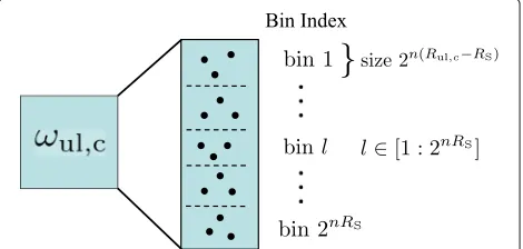
Next, we partition the uplink common messageωul,c: the common message set is divided into 2nRS equal size bins
such thatB(l)=(l−1)2n(Rul,c−RS)+1 :l2n(Rul,c−RS),l∈
[ 1 : 2nRS]. The total number of bin indices 2nRS is
deter-mined by the strength of the side channel,αS, and the bandwidth ratioW. The bin indexlis then encoded into codewordXSand sent from the uplink transmit antenna arrays over the side channel, which is shown in Fig. 3.
All the codewords are mutually independent complex Gaussian random vectors with covariance matrices given as follows to satisfy the power constraint given in (4):
EXdlXdl†
= 1
Mdl
IMdl, E
UulUul†
= 1
Mul
IMul+ ¯λρIH
† IHI
−1
ESulS†ul
= 1
Mul
IMul−E
UulUul†
, E
XulsXuls†
= 1
Mul
IMul,
(9)
where λ ∈ (0, 1),λ¯ +λ = 1. The parameterλdenotes the fraction of power allocated to the side channel. For the power splitting between the uplink private and common message, we set the power of the private message such
that its received signal strength is below the noise floor at each unintended receiver’s antenna. And we allocate the power of the codewords equally among the transmit antenna array.
Now, we describe the decoding process. The decod-ing at the BS is straightforward. Upon receivdecod-ingYul, the BS decodes (ωul,c,ωul,p). The achievable rate region of (Rul,c,Rul,p) is the capacity region of multiple-access chan-nel denoted asC1, where
Rul,c≤I(Sul;Ydl|Xdl)
Rul,p≤I(Uul;Yul|Sul)
Rul,c+Rul,p≤I(Sul,Uul;Yul)
(10)
The decoding at the downlink receiver has two stages as shown in Fig. 4. In stage one, upon receivingYS, the down-link receiver first decodes the bin index l from the side channel. In stage two, upon receiving Ydl, the downlink receiver decodes (ωdl,ωul,c) with the help of side-channel information while treating uplink private messageωul,pas noise.3This is a multiple-access channel (MAC) with side channel whose capacity region denoted asC2is given in [6] ; hence, we have
Rdl≤I(Xdl;Ydl|Sul)
Rul,c≤I(Sul;Ydl|Xdl)+I(XS;YS)
Rdl+Rul,c≤I(Xdl,Sul;Ydl)+I(XS;YS).
(11)
The achievable rate region of side-channel-assisted full-duplex network is the set of all (Rdl,Rul) such that
Rdl,Rul = Rul,c +Rul,p satisfying that (Rul,c,Rul,p) ∈ C1 and(Rdl,Rul,c) ∈ C2. Using Fourier-Motzkin elimination, the achievable rate pairs(Rdl,Rul)are constrained by the following rate region
Rdl≤I(Xdl;Ydl|Sul)
Rul≤min{I(Sul,Uul;Yul),I(Uul;Yul|Sul) +I(Sul;Ydl|Xdl)+I(XS;YS)}
Rdl+Rul≤I(Uul;Yul|Sul)+I(Xdl,Sul;Ydl) +I(XS;YS).
(12)
Fig. 4Decoding at downlink receiver
The achievable rate region given above is calculated in Appendix 2; thus, we can obtain the explicit achievable rate expression in Lemma 2.
3.3 High SNR approximation
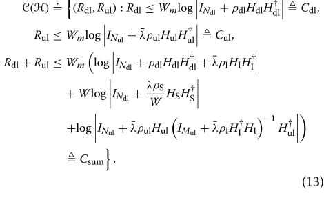
From Theorem 1, vector bin-and-cancel scheme achieves the capacity region to within a constant bit for all val-ues of channel parameters under time-invariant channels. In the high SNR limit, a constant number of bits (which do not vary with respect to SNR) are insignificant and can be ignored on the scale of interest. Therefore, we can establish the high SNR capacity region approximation to withinO(1)in the following corollary.
Corollary 1For a given the channel realization H, vector bin-and-cancel is asymptotically capacity
achiev-ing and the asymptotic capacity approximation C(H) is
given by
C(H)=. (Rdl,Rul):Rdl≤Wmlog INdl+ρdlHdlH †
dl Cdl,
Rul≤Wmlog INul+ ¯λρulHulH †
ul Cul,
Rdl+Rul≤Wm
log INdl+ρdlHdlH †
dl+ ¯λρIHIHI†
+Wlog INdl+ λρS
WHSH †
S
+log INul+ ¯λρulHul
IMul+ ¯λρIH †
IHI
−1
Hul†
Csum
.
(13)
The high SNR capacity approximation can be used to derive the generalized degrees-of-freedom (GDoF). The GDoF captures the asymptotic behavior of the capacity and the corresponding optimal schemes, allowing differ-ent links to grow at disparate rates.
TheGDoFregion is defined as follows4
(DoFdl,DoFul):DoFi=ρ→∞lim
Ri(ρi)
Wmlogρ
, i∈ {dl, ul}
and (Rdl,Rul)∈C(H)
,
(14)
Corollary 2Assuming αdl = αul = 1, the GDoF
region of(Mdl,Ndl,Mul,Nul)side-channel-assisted MIMO
full-duplex network satisfies the following constraints
DoFdl≤mdl, DoFul≤mul,
DoFdl+DoFul≤f
Nul,
(1−αI)+,mI
,1,(Mul−Ndl)+
+f(Ndl,(αI,Mul),(1,Mdl))+Wf(Ndl,(αS,Mul)), (15)
where mdl = min{Mdl,Ndl},mul = min{Mul,Nul},mI = min{Mul,Ndl} as defined in (8); function f
x,(y1,x1), (y2,x2)
=min{x,x1}y+1 +min{(x−x1)+,x2}y+2 for y1≥y2.
ProofThe proof is akin to [17] (see Appendix 3), so we
will only provide an interpretation of theGDoFresult here. First, the DoF of downlink and uplink is limited by the number of transmit and receive antennas, much like the point-to-point MIMO channel. Next, we will explain the sum GDoF. Let DoFul,c andDoFul,p denote the DoF of the uplink common message and private message, respectively.
Adopting the singular value decomposition (SVD), we can decompose the interference channel asHI = UV†, where U and V are Ndl × Ndl and Mul × Mul unitary matrices, respectively,isNdl×Muldiagonal matrix con-taining singular values ofHI. Thus,HIis decomposed into
mIparallel channels, leaving(Mul−mI)+=(Mul−Ndl)+ effective inputs at uplink transmitter that do not cause any interference to the downlink receiver. The uplink trans-mitter divides the private streams into two parts. The first part is sent along the(Mul−Ndl)+-dimensional null space of interference channelHIand reaches BS at an SNR of ρwithNulreceive antennas. In the remainingmI dimen-sions, the second part is transmitted at a power level of
ρ−αI such that it reaches the unintended receiver at the
noise floor and reaches BS at an SNR ofρ(1−αI)+. The
pro-cess can be viewed as a combination of signal space and signal scale interference alignment. Thus, theDoFof the uplink private message is
DoFul,p=f
Nul,
(1−αI)+,mI
,1,(Mul−Ndl)+
. (16)
Since the common message can be decoded at both receivers, the downlink receiver withNdl receive anten-nas is a side-channel-assisted multiple-access channel receiver. The downlink message ωdl reaches the down-link receiver at an SNR ofρ withMdltransmit antennas. The uplink common messageωul,creaches the downlink receiver through both main-channel at an SNR ofραI
and-side channel as an orthogonal spectral space at an SNR of
ρWαSwithMultransmit antennas. Thus, we have
DoFdl+DoFul,c=f(Ndl,(αI,Mul),(1,Mdl)) +Wf(Ndl,(αS,Mul)).
(17)
Combining (16) and (17) leads to the sumGDoF.
Remark 1When W =0, i.e., there is no side channel, the
GDoFis the same as that of MIMO Z-interference channel
in[17]; hence, we conclude that the implicit feedback at the
full-duplex capable BS does not help improveGDoFregime
in the two-user MIMO full-duplex network.
This is due to the fact that there is only one-sided interfer-ence. When W >0, the implicit feedback is still not useful
in terms ofGDoF, because our scheme does not rely on any
feedback.
3.4 Special cases
In this section, we give several special cases to illustrate theGDoFresults above.
Theorem 2(Case A) When Mdl = Mul = M,Ndl =
Nul = N, and αul = αdl = 1, the sum GDoF per
antenna denoted as GDoFsum
min(M,N) for the symmetric
side-channel-assisted MIMO full-duplex network is given by
GDoFsum min(M,N)
= ⎧ ⎪ ⎪ ⎨ ⎪ ⎪ ⎩
min
2, 2−
2− max(min(MM,,NN))
+
αI+WαS
αI<1,
min
2,αI+ min(max(MM,,NN))−1+WαS)
αI≥1.
In this case, one can observe that the sumGDoF per antenna increases linearly with the antenna ratiomax(min(MM,,NN)) and side-channel qualityWαS.
Another case of interest is when the BS has more antennas than mobile clients, i.e.,Mdl,Nul≥Mul,Ndl. This scenario is almost always true in practical systems and the ongoing trend is that the BS can accommodate many antennas such as in massive MIMO systems [15], while the small-form factor mobiles will have a relatively fewer antennas due to its physical size constraint.
Theorem 3(Case B) When BS has more antennas than mobiles, i.e., Mdl,Nul≥Mul,Ndl withαul = αdl = 1, the
sumGDoFper antenna denoted as GDoFsum
min(Mul,Ndl) is given as
GDoFsum min(Mul,Ndl)
= ⎧ ⎪ ⎨ ⎪ ⎩
min
mX
mI +1,
mX
mI +1−αI+WαS
αI<1
min
mX
mI +1,
mX
mI −1+αI+WαS
αI≥1.
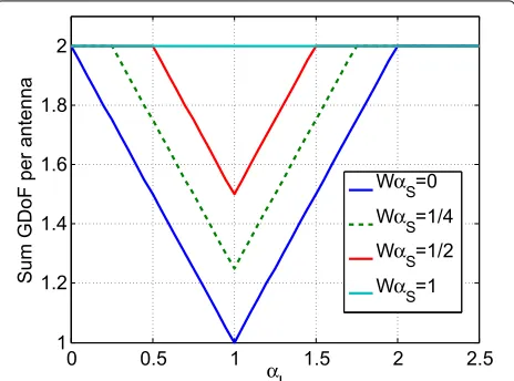
Figure 5 illustrates how the sum GDoF per antenna varies as the side-channel quality changes whenMul=Ndl given an excess of antennas at BS. WhenWαS = 0, i.e., there is no side channel, the curve maintains “V” shape as in the Z-interference channel. WhenWαSincreases, the curve gradually becomes a lifted “V” and finally reach the maximum sumGDoFper antenna of 2 for all regimes that one can achieve without interference.
We also give an example to clarify the DoF of vec-tor bin-and-cancel in Case B assuming αI = αS = 1. Using the standard MIMO SVD of channel matrices, the interference channel and side channel can be converted to mI = min{Ndl,Mul} parallel paths from uplink node TxU to downlink node RxD. In Fig. 6, the diagonalized interference and side-channel paths are depicted in bold.
In Fig. 6, the base station TxBsends Ndl independent streams to downlink node RxD, which is indicated by the black circles. Uplink node TxUsets(1−W)mI effective inputs5 to zero, which is indicated by the white circles; TxUthen sends(Mul−Ndl)+-independent private streams in the null space of the signal from TxB andWmI com-mon message which can be heard at RxD. Using vector bin-and-cancel, each transmitter sends WmI streams of its common message to the interfering receiver through the side channel, which is indicated by the blue circles. At the downlink receiver RxD,WmIstreams of the inter-fering message can be canceled out; thus, downlink can achieve Ndl DoFs and uplink can achieve min
(Mul −
Ndl)++ WmI,Mul
DoFs. Thus, in total, we can obtain minmax{Ndl,Mul} +WmI,Ndl+Mul
DoFs.
3.5 GDoF without CSIT
Acquiring the CSIT incurs a large overhead, especially in a MIMO system with many antennas. Hence, it is of prac-tical interest to study theGDoFperformance of the system without CSIT.
Fig. 5The sum GDoF per antenna forMul=Ndlwhen BS has an excess of antennas
Fig. 6The DoF-optimal scheme of two-user side-channel-assisted MIMO full-duplex network whenMul≥Ndl
We first describe the encoding and decoding strategy under the no-CSIT assumption. Both transmitters encode their messages using independent Gaussian codebooks for the main-channel. The uplink transmitter sends common message only and applies vector bin-and-cancel scheme. The side-channel bins all the uplink message and encodes the bin indices using an independent Gaussian code-book. From the downlink user’s perspective, the channel is a MAC with side channel. At the decoding process, the downlink user uses joint maximum likelihood (ML) decoder to decode both downlink message and uplink messages with the help of side channel. Hence, we can obtain the achievable rate regionRNo-CSITas
RNo-CSIT=
(Rdl,Rul):Rdl≤Wmlog
INdl+ ρdl MdlHdlH
†
dl ,
Rul≤Wmmin
log INul+
¯ λρul Mul
HulHul†
, log INdl+
¯ λρI Mul
HIHI†
+Wlog INdl+ λρS WMulHSH
†
S ,
Rdl+Rul≤Wm
log INdl+ ρdl Mdl
HdlHdl†+ ¯ λρI Mul
HIHI†
+Wlog INdl+ λρS WMul
HSHS† ,
(18)
whereλ∈(0, 1), for instance, we can fixλ= ¯λ=0.5. The achievable rate region given above can be calculated easily from Eq. (12) with uplink private message set to null and equal power allocation among transmit antennas which does not require any CSIT.
Now, we can obtain the lower bound of theGDoFunder the no-CSIT assumption.
Corollary 3Assuming αdl = αul = 1 and
side-channel-assisted MIMO full-duplex network satisfies the following constraints
DoFdl≤mdl, DoFul≤min{mul,αImI+WαSmI}, DoFdl+DoFul≤f
Ndl,(αI,Mul),(1,Mdl)
+WfNdl,(αS,Mul)
.
(19)
ProofThe achievableGDoFregion without CSIT can be
derived following the same argument as in the case with CSIT.
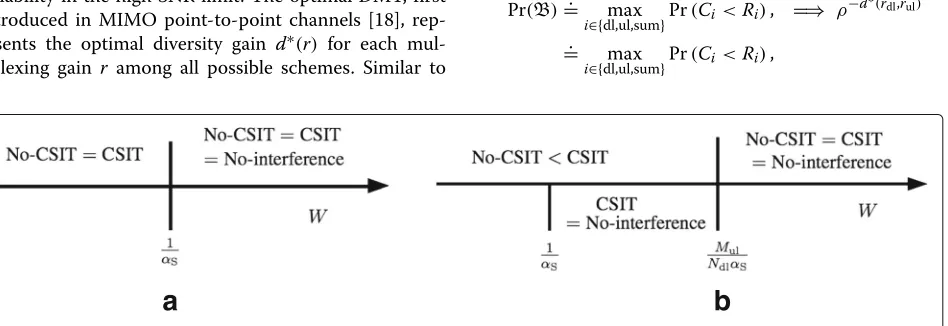
Remark 2Comparing Corollaries2and3, we conclude that whenαI≥1and Ndl≥Mul, acquiring CSIT is of no use
as theGDoFwithout CSIT achieves the optimalGDoFwith
CSIT. In the strong interference regime whereINR > SNR,
larger number of receiver antennas is sufficient to null out
the interference to achieve the optimalGDoFregime.
3.6 Spatial and spectral tradeoff in GDoF
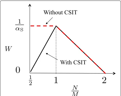
In this section, we will compare three systems: (i) the side-channel-assisted full-duplex network with CSIT, (ii) the side-channel-assisted full-duplex network without CSIT, and (iii) an idealized full-duplex network without inter-ference, i.e., a parallel uplink and a downlink channel; the last network provides us the benchmark for the best possible performance. By comparing these three systems, we aim to quantify the relationship between the spatial resources of multiple antennas and spectral resources of the side channel. We start by presenting several corollaries to Theorems 2 and 3.
Corollary 4(Case A with CSIT) The effect of interfer-ence can be completely eliminated if the bandwidth ratio of the side channel to the main channel satisfies the following condition,
WCSIT=
⎧ ⎨ ⎩
αI
αS
2−max(min(MM,,NN))
+
, forαI<1,
1 αS
3−max(min(MM,,NN))−αI
+
, forαI≥1.
(20)
From Corollary 4, we can see that the required band-width ratio is a linearly decreasing function of the antenna number ratio max(min(MM,,NN)) to achieve the interference-free performance. Therefore, the spatial resources of the num-ber of antennas at transmitters and receivers is inter-changeable with the spectral resources of the side-channel bandwidth to eliminate interference. The intuition behind it is that the additional spatial signaling dimension to perform transmit/receive beamforming is equivalent to leveraging the extra spectral signaling dimension of the side channel for interference cancelation.
From Corollary 3, we can also find out the required bandwidth ratio under the no-CSIT assumption in order to achieve the no-interference upper bound. The required bandwidth ratio without CSIT in Case A for αI = 1 is given by
WNo-CSIT=
⎧ ⎨ ⎩
1 αS
2−MN+, forN≥M,
1
αS, forM>N.
(21)
Corollary 5(Case B with CSIT) The effect of interfer-ence can be completely eliminated if the bandwidth ratio of the side channel to the main channel satisfies the following condition:
WCSIT=
⎧ ⎨ ⎩
αI
αS, forαI<1,
(2−αI)+
αS , forαI≥1.
We observe that in Case B, the required side-channel bandwidth to achieve the no-interference sum GDoF is not affected by the number of antennas in the system but received interference signal strength and side-channel signal strength levels. For αI < 1, lower interference level requires less side-channel bandwidth while forαI≥1, higher interference level leads to smaller side-channel bandwidth requirement.
In Case B, we can also derive the required bandwidth ratio under the no-CSIT assumption from Corollary 3, to achieve the no-interference performance. The required bandwidth ratio without CSIT in Case B forαI=1 is given by
WNo-CSIT=
⎧ ⎨ ⎩
1
αS, forNdl≥Mul,
Mul
NdlαS, forMul>Ndl.
(22)
In Figs. 7 and 8, we show the spatial and spectral trade-off in both Case A and Case B whenαI = 1. We observe
Fig. 8Spatial spectral tradeoff in Case B whenαI=1
that when there are more downlink receive antennas than uplink transmit antennas, obtaining CSIT is unavailing since with and without CSIT requires the same amount of side-channel bandwidth to completely eliminate inter-ference. However, when we have more uplink transmit antennas, if we do not have CSIT, the extra spatial degrees-of-freedom are wasted and we need more side-channel bandwidth to achieve the no-interference performance.
In Fig. 9, we give an illustration of the comparisons of the three systems inDoFas a function of the side-channel bandwidth when there is an excess of BS antennas.
4 Diversity and multiplexing tradeoff of MIMO-distributed full-duplex
In this section, we consider a slow-fading scenario. When the channel experiences slow fading, an important metric to characterize the MIMO system performance is the diversity and multiplexing tradeoff (DMT), which delin-eates the asymptotic tradeoff between data rate and reliability in the high SNR limit. The optimal DMT, first introduced in MIMO point-to-point channels [18], rep-resents the optimal diversity gain d∗(r) for each mul-tiplexing gain r among all possible schemes. Similar to
our definition ofGDoF, we define the multiplexing gain of both downlink and uplink channels in our system as follows:
ri=ρ→∞lim
Ri(ρi)
Wmlogρ
, i∈ {dl, ul}, (23)
whereRdlandRulare the achievable rates (bit/s) of down-link and updown-link, respectively.
Assuming the overall average error probability is
Pe(rdl,rul), the DMT is
d(rdl,rul)=ρ→∞lim −
logPe(rdl,rul)
logρ . (24)
We define dopt(rdl,rul) as the supremum of d(rdl,rul) computed over all possible schemes. Thus,dopt(rdl,rul)is the optimal DMT of the system.
In this section, we will study the DMT performance under different assumptions regarding the availability of CSIT. We assume that the channel knowledge is known at the receivers. In the following, we will first obtain the optimal DMT with CSIT which can be achieved by vec-tor bin-and-cancel as described in the Section 3. Next, we study the case without CSIT and derive the correspond-ing achievable DMT. Finally, based on the DMT result, we will investigate the spatial and spectral tradeoff as well as the interplay between CSIT and side channel.
4.1 With CSIT case
In a slow-fading scenario, the channel matrices remain fixed over a fade period with a short-term power con-straint given in (4); thus, the capacity region in time-invariant channels can serve as instantaneous capacity region in each fade period. We define the outage event as the target rate pair not contained in the instantaneous capacity region: B {(Rdl,Rul) /∈ C(H)}, whereC(H) is given in Corollary 1. From [18], it can be easily shown thatPe∗(rdl,rul)=. Pr(B), whereP∗e(rdl,rul)is the infimum of the overall average error probability among all possible schemes. In the high SNR limit, we can obtain that
Pr(B)=. max
i∈{dl,ul,sum}Pr(Ci<Ri), =⇒ ρ
−d∗(rdl,rul)
.
= max
i∈{dl,ul,sum}Pr(Ci<Ri),
a
b
whereCiis given in (13) andRsum =Rdl+Rul. Thus the optimal diversity order is
d∗(rdl,rul)= min
i∈{dl,ul,sum}dBi(ri), wheredBi(ri)
= lim
ρ→∞−
logPr(Ci<Wmrilogρ)
logρ ,
(25)
In the Section 3, we showed that vector bin-and-cancel achieves the asymptotic capacity region. Hence, in the asymptotic DMT characterization, the optimal DMT with CSIT can be achieved by vector bin-and-cancel which only requires CSIT of the interference channel between the up- and downlink nodes since the uplink message splitting depends on the interference channel. The deriva-tion of the optimal DMT curve of side-channel-assisted MIMO full-duplex network follows from two steps. In [18], we know that the optimal DMT for MIMO point-to-point channel is dM,N(r) = (M− r)(N −r), which is a piecewise linear curve joining the integer pointr ∈
[0, min(M,N)]. For a general channel levelαi,i ∈ {dl, ul} of a point-to-point channel, we will invoke Lemma 6 (in Appendix 3) for our calculation. Hence, we first obtain the optimal diversity order of each individual downlink and uplink given as
dBi(ri)=αidMi,Ni
ri
αi
,∀ri∈[0, min{Mi,Ni}αi] ,
i∈ {dl, ul}.
(26)
Next, we evaluatedBsum(rsum)in the following lemma.
Lemma 3The diversity order with CSIT given the sum multiplexing gain of both uplink and downlink is the min-imum of the following objective function:
dBsum(rsum)= min ¯
μ,σ¯,θ¯,ν¯ mdl
i=1
(Mdl+Ndl+1−2i) μi
+
mul
j=1
Mul+Nul+1−2j
σj−(Mdl+Nul)mIαI
+
mI
k=1
(Mdl+Nul+Mul+Ndl+1−2k) θk
+
mI
l=1
(Mul+Ndl+1−2l)νl
+
mdl
i=1
min{Ndl−i,Mul}
k=1
(αI−μi−θk)+
+
mul
j=1
min{Mul−j,Ndl}
k=1
αI−σj−θk+;
Subject to mdl
i=1
(α1−μi)++ mul
j=1
α2−σj++ mI
k=1
(αI−θk)+
+W mI
l=1
(αS−νl)+<rsum;
0≤μ1≤ · · ·μmdl; 0≤σ1≤ · · ·σmul; 0≤θ1
≤ · · ·θmI; 0≤ν1≤ · · ·νmI; μi+θk≥αI,∀(i+k)≥Ndl+1; σj+θk≥αI,∀(j+k)≥Mul+1,
(27)
where μ¯ = {μ1,· · ·,μmdl},σ¯ = {σ1,· · ·,σmul},θ¯ = {θ1,· · ·,θmI},ν¯ = {ν1,· · ·,νmI}and mdl, muland mIare defined in(8).
ProofWe provide the proof in Appendix 4.
WithdBi fori ∈ {dl, ul, sum}derived above, we have
the following theorem which gives the optimal DMT in its most general form, allowing different channel parame-ters and multiplexing gains for uplink and downlink with arbitrary number of antennas at each node.
Theorem 4The optimal DMT of (Mdl,Ndl,Mul,Nul)
side-channel-assisted MIMO full-duplex network with CSIT denoted as dCSIT,optis given by
d(CSIT,optM
dl,Ndl,Mul,Nul)(rdl,rul)=i∈{dl,ul,sum}min dBi(ri),
where dBi(ri)is given in(26)and Lemma3.
The optimization problem in Lemma 3 is a convex opti-mization problem [19] with linear constraints, which can be solved using linear programming. The general form of the optimal DMT with CSIT in Theorem 4, though can be calculated using numerical methods, does not result in a form solution. In the following corollary, a closed-form DMT result is derived in the case of single-antenna mobiles communicating with multiple-antenna BS withM
transmit and receive antennas, i.e.,Mdl=Nul=M.
Corollary 6In the case of(M, 1, 1,M) with symmetric
DMT rul=rdl= r whenαdl=αul=αI=1. The
closed-form optimal DMT with CSIT is given which completely characterizes the optimal DMT under all side-channel conditions:
• whenW ≤2M1+1andWαS<1,
dCSIT,opt(M,1,1,M)(r)
=
M(1−r), 0≤r≤M+1+(2M+1)WαS 3M+2
(2M+1)(1+WαS)−(4M+2)r, M+1+3(2MM++21)WαS≤r≤1+Wα2 S
• when2M1+1≤W < M2,αS≥M2, andWαS<1,
dCSIT,opt(M,1,1,M)(r)=
M(1−r), 0≤r≤β∗
αS+W1(1−2r), β∗≤r≤ 1+W2αS (29)
• whenW≥2M1+1,αS< M2, andWαS<1,
dCSIT,opt(M,1,1,M)(r)
= ⎧ ⎪ ⎨ ⎪ ⎩
M(1−r), 0≤r≤ M+1+αS
3M+2 2M+1+αS−(4M+2)r, M3+1+αM+2S ≤r≤ 12 αS+ W1(1−2r), 12≤r≤ 1+W2αS
(30)
• whenW≥2M1+1,αS< M2, andWαS≥1,
dCSIT,opt(M,1,1,M)(r)
= ⎧ ⎪ ⎪ ⎨ ⎪ ⎪ ⎩
M(1−r), 0≤r≤ M+1+αS
3M+2 2M+1+αS−(4M+2)r, M3+1+αM+2S ≤r≤ 12 αS+ W1(1−2r), 12≤r≤β∗
M(1−r), β∗≤r≤1
(31)
• whenαS≥M2 andWαS≥1,
dCSIT,opt(M,1,1,M)(r)=M(1−r), 0≤r≤1 (32)
whereβ∗= αS+W1−M 2
W−M
.
ProofThe DMT of the point-to-point channel isM(1−
r),∀r ∈ [0, 1]. Thus, we only need to solve for the opti-mization problem given sum multiplexing gain. One way to find the minimum of the optimization problem in Lemma 3 is to apply the Karush-Kuhn-Tucker condition. Here, we will provide another approach which is the key to the proof of a general case. The method we adopt is gradient descent which finds the local optimum. Since the optimization problem we have is convex with linear constraints, the local optimum is actually the global opti-mum in convex optimization [19]. Hence we can obtain the global optimum via gradient descent algorithm.
We first simplify the objective function of the diversity order in Lemma 3 given sum multiplexing gain. By sub-stitutingνl = Wνl in (27), we can express the objective function as
dsumCSIT=minMμ1+Mσ1+(2M+1)θ1+ ν 1
W −2M,
Subject to (1−μ1)++(1−σ1)++(1−θ1)+ +(WαS−ν1)+<rsum;
μ1,σ1,θ1,ν1≥0; μ1+θ1≥1;σ1+θ1≥1.
(33)
Next, we differentiate the objective function in (33) with respect to different variables
∂dCSITsum
∂ν 1
= 1
W; (34)
∂dCSITsum
∂θ1 =
2M+1; (35)
∂dCSITsum
∂μ1 =
∂dsumCSIT
∂σ1 =
M< ∂d
CSIT sum ∂θ1
. (36)
Comparing the gradient of each variable, when W ≤
1
2M+1, the steepest descent of the objective function is along the decreasing value ofν1 withθ1= μ1 =σ1 =1, forrsum ≤ Wαs. Thus, we havedsumCSIT(r) = 2M+ 1+ αS− rsumW ,∀rsum ∈ [0,WαS] . This also implies that for
rsum≥Wαs, ν1 = 0 in the optimal solution. Now, the steepest descent of the objective function in (33) is along the decreasing value of θ1 with μ1 = σ1 = 1, and the corresponding minimum isdCSIT
sum(rsum) = (2M+1)(1+
WαS)−(2M+1)rsum,∀rsum∈[WαS, 1+WαS] . WhenW≥2M1+1, the steepest descent of the objective function is along the decreasing value of θ1 with μ1 = σ1 = 1,ν1 = WαS, for rsum ≤ 1. Thus, we have
dsumCSIT(rsum)=2M+1+αS−(2M+1)rsum,∀rsum∈[0, 1] . Again, forrsum≥1, the optimal solution has θ1 = 0. We will rewrite the objective function as
dCSITsum =minMμ1+Mσ1+ ν 1
W −2M,
Subject to (1−μ1)++(1−σ1)++(WαS−ν1)+ ≤rsum−1;
μ1,σ1,ν1≥0; μ1≥1; σ1≥1.
(37)
To minimize the objective function above, we should let μ1 = σ1 = 1. Hence, the minimum of the objective function is dCSITsum (rsum) = αS+ W1(1 −rsum),∀rsum ∈ [1, 1+WαS] . Now, combining all the results above, we have
dCSIT,opt(M,1,1,M)(r)=min{M(1−r),dCSITsum(M,1,1,M)(r)}
for 0≤r≤1. (38)
wheredCSITsum(M,1,1,M)(r)is given as
• whenW ≤ 2M1+1
dCSITsum(M,1,1,M)(r)
=
2M+1+αS−W2r, 0≤r≤ W2αS (2M+1)(1+WαS)−(4M+2)r, W2αS ≤r≤ 1+W2αS
• whenW≥2M1+1
dCSITsum(M,1,1,M)(r)
=
2M+1+αS−(4M+2)r, 0≤r≤ 12 αS+W1(1−2r), 12 ≤r≤ 1+W2αS
(40)
Further simplification of (38) will lead to the analytical expression in Corollary 6.
Remark 3The optimal DMT with CSIT in the no
side-channel case is a special case of Corollary6when W =0,
and is given as
d(No-SC,CSIT,optM,1,1,M) (r)=
M(1−r), 0≤r≤ 3MM+1+2
(2M+1)(1−2r), 3MM+1+2≤r≤ 12
(41)
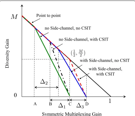
From Corollary 6, we can completely quantify the improvement of DMT with side channel under all side-channel conditions. Figure 10 depicts the comparison of DMT with/without (w/wo) side channel whenW =
1
2M+1,αS = M2. We define the light loading threshold as the multiplexing gain threshold within which the system error event is dominated by single-user performance. In the case with CSIT, the light loading threshold of the sys-tem without side channel isBshown in Fig. 10. Whenr> B, the dominant error event is that all users are in error. With the help of side channel, the light loading threshold
Fig. 10DMT comparison w/wo side-channel w/wo CSIT when W= 2M1+1,αS= M2
is increased by 1, where1 = (2M3+1)M+2WαS. Moreover, we can see that the side channel also improves system maximum multiplexing gain (when the diversity order is zero) by3, where3= W2αS. Both improvement amount 1and3will scale with side-channel qualityWαS( for
W ≤ 2M1+1) till either pointCorDreaches the symmetric maximum multiplexing gain of one which corresponds to the no-interference point.
When W = 2M1+1,αS = M2, we have 1 = 6MM+4 and 3 = 8MM+4. We conclude that in this case, both improvement amount 1 and 3 will scale with the number of antennas at the BS. In the limit of M (as in massive MIMO, BS has unlimited number of anten-nas), we will have improvement of limM→∞1 = 16 and limM→∞3= 18.
4.2 Without CSIT case
We define the outage eventOin the case without CSIT as the target rate pair does not lie in the achievable rate regionRNo-CSIT:O {(Rdl,Rul) /∈ R}, whereRis given (withλ= ¯λ=0.5)
R=
(Rdl,Rul):Rdl≤Wmlog
INdl+
ρdl
Mdl
HdlHdl†
;
Rul≤Wmlog
INul+
¯ λρul
Mul
HulHul†
;
Rdl+Rul≤Wm
log INdl+
ρdl
Mdl
HdlHdl† +
¯ λρI
Mul
HIHI†
+Wlog INdl+
λρS
WMul
HSHS†
,
(42)
The difference between (42) and the achievable rate region in (18) is that (42) does not have a constraint onRul for the transmission from up- to downlink mobile. This is because the downlink mobile is not interested in the uplink’s message, thereby the failure of decoding uplink’s message alone will not be declared as an error event at the downlink receiver.
Under the no-CSIT assumption, the diversity order of each MIMO downlink/uplink channel is still the same as given in (26). As for the diversity order for a given sum multiplexing gain, it is characterized by the following lemma.
dosum(rsum)=min
¯ μ,θ,¯¯ν
mdl
i=1
(Mdl+Ndl+1−2i) μi
+
mI
k=1
(Mul+Ndl+Mdl+1−2k) θk
+
mI
l=1
(Mul+Ndl+1−2l) νl−MdlmIαI
+
mdl
i=1
min{Ndl−i,Mul}
k=1
(αI−μi−θk)+
Subject to mdl
i=1
(αdl−μi)++ mI
k=1
(αI−θk)+
+W
mI
l=1
(αS−νl)+<rsum;
0≤μ1≤ · · · ≤μmdl; 0≤θ1≤ · · · ≤θmI; 0≤ν1≤ · · · ≤νmI; μi+θk≥αI, ∀(i+k)≥Ndl+1;
(43)
ProofWe provide the proof in Appendix 5.
Theorem 5A lower bound of the DMT of (Mdl,Ndl,
Mul,Nul) side-channel-assisted MIMO full-duplex
net-work without CSIT is given as
dNo-CSIT(Mdl,Ndl,Mul,Nul)(rdl,rul)= min
i∈{dl,ul,sum}doi(ri).
where doi(ri)is given in(26)and Lemma4.
While the general form of the lower bound of DMT without CSIT is given in Theorem 5, we provide the closed-form no-CSIT DMT in the following corol-lary when single-antenna mobiles communicate with multiple-antenna BS in line with the analysis in the Section 4.1.
Corollary 7In the case of(M, 1, 1,M)with symmetric
DMT rul = rdl = r whenαdl = αul = αI = 1. The
closed-form lower bound of the DMT without CSIT is given that completely characterizes the achievable DMT under all side-channel conditions:
• whenW ≤ M1+1andWαS<1,
dNo-CSIT(M,1,1,M)(r)
=
⎧ ⎨ ⎩
M(1−r), 0≤r≤1+(M+1)WαS M+2
(M+1)(1+WαS)−(2M+2)r, 1+(M+1)WαS M+2 ≤r≤
1+WαS 2
(44)
• whenM1+1 ≤W< M2,αS≥M2, andWαS<1,
dsum(No-CSITM,1,1,M)(r)=
M(1−r), 0≤r≤β∗
αS+W1(1−2r), β∗≤r≤ 1+W2αS (45)
• whenW≥M1+1,αS< M2, andWαS<1,
dNo-CSITsum(M,1,1,M)(r)= ⎧ ⎪ ⎪ ⎨ ⎪ ⎪ ⎩
M(1−r), 0≤r≤ 1+αS M+2
M+1+αS−(2M+2)r, 1M++α2S ≤r≤12 αS+W1(1−2r), 12 ≤r≤ 1+W2αS
(46)
• whenW≥M1+1,αS< M2, andWαS≥1,
dNo-CSITsum(M,1,1,M)(r)= ⎧ ⎪ ⎪ ⎪ ⎪ ⎨ ⎪ ⎪ ⎪ ⎪ ⎩
M(1−r), 0≤r≤1+αS
M+2
M+1+αS−(2M+2)r, 1M++α2S ≤r≤ 12 αS+W1(1−2r), 12≤r≤β∗
M(1−r), β∗≤r≤1
(47)
• whenαS≥M2 andWαS≥1,
dNo-CSITsum(M,1,1,M)(r)=M(1−r), 0≤r≤1 (48)
whereβ∗= αS+W1−M 2
W−M
.
Proof The proof is similar to that in Corollary 6 which
uses gradient descent method.
Remark 4 The lower bound of the DMT without CSIT
in the no side-channel case is a special case of Corollary7
when W =0, and is given by
dNo-SC,No-CSIT(M,1,1,M) (r)=
M(1−r), 0≤r≤ M1+2
(M+1)(1−2r), M1+2≤r≤ 12
(49)
Remarks 3 and 4 describe the DMT without side chan-nel under CSIT and no-CSIT assumptions. One can easily verify that the no-side-channel cases in [20, 21] w/wo CSIT are special cases incorporated in our derivation of DMT.
Now we compare the lower bound of the DMT w/wo side channel under the no-CSIT assumption. WhenW ≤
1
see that the side channel is more effective in increasing the DMT performance in the lack of CSIT as2≥1.
4.3 Spatial and spectral tradeoff in DMT
In this section, we will derive symmetric DMT in closed form for a more general case where the mobiles have mul-tiple antennas communicating with the BS withM trans-mit and receive antennas. Using the closed-form DMT expressions, again we will compare the three systems: with and without CSIT and the no-interference-idealized full-duplex network. We will characterize the relationship between the spatial degrees-of-freedom of the antenna resources and the extra spectral degrees-of-freedom due to the side channels under slow-fading channels.
We still assume that BS has more antennas, i.e.,
M≥Mul, Ndl. The closed-form symmetric DMT of the general(M,Ndl,Mul,M)system withαdl= αul = αI =1 and rdl = rul = r are given under CSIT and no-CSIT assumptions in Lemmas 9 and 10 (in Appendix 6), respectively.
First, we ask the question that how much side-channel bandwidth is required to compensate for the lack of CSIT such that the DMT of the system without CSIT achieves that of the system with CSIT. The sufficient condition is given in the following theorem.
Theorem 6In case of (M,Ndl,Mul,M), sufficient
con-ditions such that no-CSIT DMT is the same as full CSIT DMT are given by
1. W =min
ProofWith the conditions given above, we can verify
that the symmetric DMT with CSIT in Lemma 9 is the same as the DMT without CSIT in Lemma 10.
Corollary 8When Mul > Ndl, if W < α1S, the DMT
without CSIT is strictly smaller than that with CSIT.
Corollary 8 can be readily obtained by comparing Lemmas 9 and 10. IfMul>NdlandW < α1S, the availabil-ity of CSIT is crucial in performing transmit beamforming to yield higher DMT.
The next question we will ask is how much side-channel bandwidth is required to eliminate the effect of inter-ference such that the DMT of the system w/wo CSIT achieves that of a system without interference. The follow-ing theorem characterizes the effect of the side-channel
bandwidth on the performance of the symmetric DMT to reach no-interference DMT.
Theorem 7In case of (M,Ndl,Mul,M), the
suffi-cient conditions are given under CSIT and no-CIST assumptions, respectively, where the effect of interference can be completely eliminated to achieve the optimal no-interference DMT:
ProofWe need to show that with the conditions above,
the DMT of our system w/wo CSIT is not domi-nated by the diversity order given sum multiplexing gain
dw/wo CSITsum(M,N
dl,Mul,M)(rsum), ∀r ∈ [0,mI] . It is sufficient if we
show that the conditions above indicate that the decay slope ofdsum(w/wo CSITM,N
dl,Mul,M)(rsum) is larger than that of the
PTP channel dM,mI(r)∀r, and the maximum
symmet-ric multiplexing gain of dw/wo CSITsum(M,N
dl,Mul,M)(rsum) is larger formance will be improved as side-channel bandwidth ratio W increases. Therefore, with W large enough,
dw/wo CSITsum(M,N
dl,Mul,M)(rsum) will lastly be dominated by
side-channel condition in the last admissible interval. With the special structure of the decay slope, in order to find the conditions where DMT w/wo achieves PTP performance, it suffices to show the following: (A) the decay slope of side channel given sum multiplexing gain is larger than
dM,mI(r)in their last admissible intervals, respectively, and
(B) max(rsum)≥2mI.
Under the CSIT assumption, from Corollary 3, we know the maximum sum multiplexing gain is mX +mIWαS.
. Next to meet condition (A), the decay slope of the side channel in the last interval
αSdMul,Ndl