R E S E A R C H
Open Access
A hybrid passive localization method under
strong interference with a preliminary
experimental demonstration
Bo Lei
*, Yixin Yang, Kunde Yang, Yong Wang and Yang Shi
Abstract
Strong interference exists in many passive localization problems and may lead to the inefficacy of traditional localization methods. In this study, a hybrid passive localization method is proposed to address strong interference. This method combines generalized cross-correlation and interference cancellation for time-difference-of-arrival (TDOA) measurement, followed by a time-delay-based iterative localization method. The proposed method is applied to a preliminary experiment using three hydrophones. The TDOAs estimated by the proposed method are compared with those obtained by the particle filtering method. Results show that the positions are in agreement when the TDOAs are accurately obtained. Furthermore, the proposed method is more capable of localization in the presence of a strong moving jamming source.
Keywords:Interference cancellation, Radon transform, Cross-correlation, Localization, Underwater acoustics
1 Introduction
Passive source localization is a significant and important topic in signal processing because of its minimal impact on the environment and low susceptibility to the effects of clutter. This viable approach has certain advantages in navigation [1], speaker tracking [2], radar [3], and under-water acoustics [4,5]. The time-delay-based method is the most widely used localization strategy, which is a two-step scheme. In general, time-difference-of-arrival (TDOA) measurements of a passive signal on spatially separate receivers are first estimated, followed by the solution of nonlinear hyperbolic equations using the range-difference information obtained from the product of the measured time delays and the known propagation speed. Thus, the source position can then be determined based on the sensor array geometry.
In localization, a straightforward TDOA estimation be-tween a pair of receivers can be realized by determining the peak of the cross-correlation function. A generalized cross-correlation called the phase transform (PHAT) [6], which uses the normalized spectra of the signals, is commonly used in time-delay measurements [7–9]. The
position of the source can be estimated through the intersection point of each pair of hyperbolic functions. However, since each pair can have zero, one, or two inter-sections, the logic to find the correct one is nontrivial. Also, determining the correct weighting is difficult. Solving the hyperbolic functions using nonlinear least squares has been considered as a possible approach [10], in which a Taylor-series expansion is used for linearization and the so-lution is determined iteratively. A two-step weighted least-squares algorithm proposed by Chan [11] could provide the final solution of the position coordinates by exploiting the known relation between the intermediate variable and the position coordinates. Young et al. [12] explored the use of cross-correlation-based TDOA methods for localization by a modified minimum-variance distortionless response technique. Lui [13] derived a semi-definite programming algorithm for source localization by integrating some available prior information. Friedlander [14] estimated the range and depth of an underwater source by meas-uring the propagation delay differences among multiple propagation paths on two vertically deployed receivers. Felisberto et al. [15] further developed a localization method that minimizes a time-delay objective function with respect to the depth and range with the use of a * Correspondence:[email protected]
School of Marine Science and Technology, Northwestern Polytechnical University, Xi’an 710072, China
ray-based backpropagation algorithm. Particle filtering (PF) has also been used to automate detection and localization [16, 17].
Furthermore, a number of approaches have been pro-posed for multitarget localization. A PF-based algorithm was developed for the localization and tracking of multiple acoustic sources in reverberative environments [18]. Based on maximum-likelihood estimation, a technique using two omnidirectional passive sensors for the detection and estimation of a target in the presence of false measure-ments was developed [19], where the target motion parameters are obtained by directly maximizing a joint-likelihood function. A multitarget tracking formula-tion [20] was studied as an incomplete data problem, where a maximum-likelihood estimator was derived based on an expectation–maximization algorithm [21]. The like-lihood estimator is maximized indirectly by iterating the expectation and maximization steps until certain ap-propriate convergence conditions are satisfied and is successfully applied to the state estimation of nonmaneu-vering targets in a cluttered underwater environment. A nonlinear least-square technique was used to compute the motion parameters for each target by modeling the Gaussian mixture probability density functions of TDOA measurement errors [22].
Without loss of generality, the localization technique described in this paper is based on TDOA measurement between spatially separated hydrophones. However, a problem originates from the boat-noise target signal be-ing totally polluted by strong interference. This contam-ination is common in a coastal environment and may be in the form of interference from moving merchant ships, artificial noise, and marine mammal bioacoustics, among others. If the signal-to-interference ratio is low, then localization may be inaccurate when the TDOAs of the two signals are close. Therefore, the interference has to be canceled before TDOA estimation. Accordingly, this paper presents a hybrid localization method integrated with interference cancellation. The method comprises three steps. First, PHAT processing is applied to the re-corded data. Second, an interference cancellation method involving the Radon transform [23, 24] is exploited, so that the TDOAs on each pair of receivers are accurately ac-quired. Finally, iteration is performed to search for the source position. The proposed method is validated by a
preliminary experiment, in which a moving jamming source is present.
The remainder of the paper is organized as follows: Section 2 presents the framework of the hybrid localization method. In Section 3, an experimental demonstration with three spatially separated hydrophones in a lake is provided. Section 4 further discusses the proposed method, with a moving interference taken into consideration. Section 5 presents the conclusions of this study.
2 Framework of the method
In underwater localization, the target signals are con-taminated by strong interference, and this contamination may result in inaccurate TDOA measurement. As a re-sult, the efficacy of conventional localization methods is affected. The framework of the proposed localization method, which can cancel interference, comprises three processing steps, as shown in Fig. 1. PHAT processing is first applied to the received data from each pair of re-ceivers, followed by a novel interference cancellation method involving the Radon transform, whereby, the TDOAs of the target signal are obtained. The final process is to localize the target source based on the esti-mated TDOAs of all receiver pairs.
2.1 PHAT processing
Let s(t) and p(t) represent the boat-noise target signal and interference from a jamming source, respectively, and x1(t) and x2(t) represent the signals received by two hydrophones located at distant locations and arranged in a known geometry. These two received signals are re-spectively expressed as
x1ð Þ ¼t s tð−D1Þ þp tð−Di1Þ þn1ð Þt ;
x2ð Þ ¼t s tð−D2Þ þp tð−Di2Þ þn2ð Þt ; ð1Þ
where the unknown parameters D1and D2are the time delays of the target signal on the two hydrophones, Di1 and Di2 are the time delays of the interference, and n1 and n2 are additive noises on the two hydrophones. In general, the interference is uncorrelated with the target signal s(t). Thus, TDOAs D1−D2 and Di1−Di2 may be derived as two peaks of the common cross-correlation function between the two hydrophone signals. However, if the interference-to-signal ratio is strong, the peak of the
target signal output may be buried in the interference. The PHAT method, which is a generalized cross-correlation processing method, has the capability to suppress the inter-ference power and can be mathematically expressed as
y tð Þ ¼IFFT X1ð Þf X
2ð Þf X1ð Þf
j jjX2ð Þf j
; ð2Þ
where * indicates complex conjugation and X1(f) and X2(f) are the spectra of x1(t) and x2(t), respectively. In the PHAT output y(t), two peaks corresponding to the interference and target signal are present. When both TDOAs are close, the TDOA of the target signal is diffi-cult to accurately obtain because the target-signal peak of the PHAT output is significantly obscured. Therefore, the interference should be suppressed before TDOA es-timation. Even in cases in which the two peaks are to-tally separated, the cancellation process is beneficial to automatically determine the TDOA.
2.2 Interference cancellation
If a strong jamming source exists in the background, an obvious additional peak will appear in the PHAT output. In block processing, the sampled waveform of the target signal when the source is moving is divided into blocks, and PHAT processing is applied to each of the blocks. Once the PHAT outputs are organized into a cross-correlation matrix, in which each row represents a PHAT output, a false trajectory corresponding to the peaks may be present along the running time dimension. In most cases, the trajectory does not exhibit a straight-line behav-ior. If the PHAT outputs are rearranged to generate a line for the dominant interference component, the Radon trans-form can be exploited, which is effective for line detection. On the basis of this intuition, a novel processing method is proposed for interference cancellation on the PHAT out-puts. The procedure of this method is illustrated in Fig. 2 and described as follows:
1. Successive blocks of the received signals on each receiver pair are processed using the PHAT technique to generate a cross-correlation matrix. Given that the Radon transform renders good line detection, all the peaks of the PHAT outputs, which correspond to the dominant interference component in the matrix, are aligned to generate a line along the running time axis. Thus, a new matrix is generated, as shown on the left of Fig.2. In this way, an output matrixPwith dimensionN×Mis produced, whereN is the number of processed blocks andMis the length of the PHAT output. The output matrix has a nearly straight vertical line along the running time axis, and this line corresponds to peaks of the interference cross-correlation. The offset of each PHAT peak in the processing procedure is stored in memory for later use.
2. The firstMrows ofPare selected and form the block namedP1, which is of dimensionM×Mand, in this example, covers an event when the target signal and interference have the same or similar TDOAs. The second block followingP1, namedP2, is also of dimensionM×M. The Radon transform is performed on both matrices:
P1R¼RTð ÞP1 ;
P2R¼RTð ÞP2 ; ð3Þ
where RT (∙) denotes the Radon transform. The trans-formed matrix P1R contains both the TDOA variations of the interference and target signal along the running time dimension, whereas the matrix P2R contains only information of the interference. If the target signal is partially contained in P2, then a negative peak will ap-pear in the interference cancellation result.
3. Let ΔPR=P1R−P2R, so that the interference in P1R is canceled. The inverse Radon transform (IRT) is then applied toΔPR, yielding
~
P¼IRTðΔPRÞ; ð4Þ
As shown in (4), the PHAT output of the target signal is retained, whereas that of the interference is canceled. The TDOA of the target signal can then be evaluated ac-cording to the peak position on the relative time axis by undoing the recorded offset compensation from step 1 above.
Theoretically, parameterMis independent of the mov-ing speed of the source. Only variations in the peak values of the PHAT results can degrade the jamming signal cancellation performance. If the variation in the jamming signal is weak, then a largeMvalue may be set, and vice versa.
Once the TDOAs on the receiver pairs are determined, the position of the object is further assessed by estimating the intersection point of each pair of hyperbolic functions or determining the true position values by some other method.
2.3 Localization algorithm
Nreceivers are assumed to be located at position (ai,bi), and the general formulation of TDOA distance between Receiver i and Receiver j for source position (X,Y) is mathematically described as
Δdij¼f X;Y;ai;bi;aj;bj
; 1≤i<j≤N: ð5Þ
The distance function f can be estimated using the geometry for the direct wave without boundary interaction or using a ray model for multipath propagation. The nonlinear Eq. (5) is overdetermined when N> 3, and the solution can then be derived by nonlinear least-squares estimation of (X,Y), given by
^ position of the object. Therefore, with the use of a least-squares criterion, the minimization problem in vector notation can be written as
Q̂ ¼ arg min matrix of the TDOA measurements. The minimum-variance solution can be obtained using the stochastic gradient algorithm
Qmþ1¼Qm−μmf0QðQmÞ½Δd−f Qð mÞ; ð8Þ
where f0Q indicates the derivation of functionf with
re-spect toQ. A good choice of step size is formulated by the normalization
The performance of the localization method depends on the accuracy of the TDOA measurement,Δd. ForN hydrophones, the maximum number of intersection points for each pair of hyperbolic functions is
N
Once the number of hydrophones exceeds 3, the prob-lem is overdetermined. Given time-delay errors caused by noise, waveguide fluctuation, and interference, a good solution may not be achieved if a large error exists on some of the hydrophones. Therefore, three hydrophones is a good choice for a practical localization system.
3 Experimental demonstration
3.1 Experiment configuration
A preliminary experiment was conducted in a lake with a depth of 40 m, aimed to verify the localization method under strong interference with a limited number of hy-drophones. The configuration is shown in Fig. 3. An omnidirectional broadband transmitter with center fre-quency of 10 kHz was deployed as a jamming source at a depth of 10 m and range of 1100 m. Owing to the limited conditions of this experiment, only three hy-drophones were deployed at a depth of 10 m, with the #1 and #2 hydrophones being 5 m apart and #2 and #3 hydrophones being 10 m apart. The hydrophone out-puts were followed by a pre-filter with a pass-band of 4–16 kHz (to verify the proposed method under strong interference). A boat approximately 4 m in length was traveling at a speed of approximately 0.5 m/s, based on its global positioning system (GPS).
The rays propagated from the moving boat in this envir-onment were computed using the Bellhop ray model [25, 26] with the source located at a depth of 0.5 m, as shown in Fig. 4b. Most of the rays travel downward and are then reflected from the bottom. Direct-path waveforms were re-ceived at a depth of 10 m when the source range was less than 500 m, and bounces at the boundaries occurred more than once when the source distance exceeded 700 m.
As the boat moves beyond the receiver array, a 5–15 kHz linear frequency modulation (LFM) signal was radiated from the jamming source with a duration of 0.1 s and re-peated every 0.5 s. Both the LFM signal and boat noise were simultaneously filtered and recorded. Even though the spectrum of the boat noise is lower at frequencies of only a few thousand hertz, it is more significant for the
interference cancellation study. A portion of the waveform recorded on the #1 hydrophone and its power spectrum are shown in Fig. 5. The plots show that the boat noise is approximately 25 dB lower than the LFM jamming signal and is therefore seriously contaminated.
Given that the jamming source was practically motion-less, a line in the cross-correlation output matrix should exist. Therefore, the interference cancellation procedure can be simplified in subsequent processing because PHAT peak offsets are not necessary.
3.2 Processing results and comparison
All three hydrophone outputs were used to compute the TDOAs, as described in (5). Consequently, three hyper-bolic functions were generated. The PHAT results from
Sound speed (m/s)
1460 1465 1470 1475 1480 1485 1490
Depth (m)
0
5
10
15
20
25
30
35
40
Range (km)
0 0.2 0.4 0.6 0.8 1 1.2
Depth (m)
0
5
10
15
20
25
30
35
40
)
b
)
a
Fig. 4Measured sound speed profile and propagation paths from the position of the small boat.aSound speed, showing approximately constant value at depths of more than 18 m but a negative gradient below this depth.bRay model outputs where the depth of the source (moving boat) was set to 0.5 m
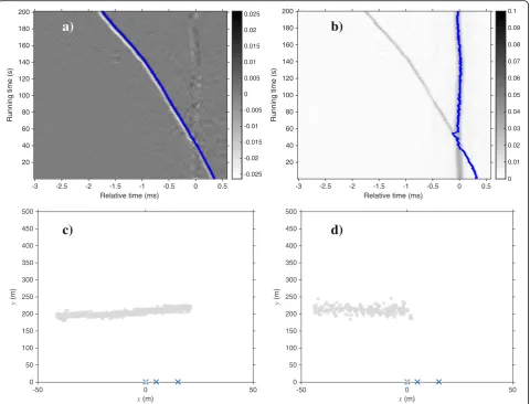
the received data on the first pair of hydrophones (#1 and #2) are shown in Fig. 6a. The peaks of the cross-correlation output of the boat noise are evident, owing to the spectral normalization of the interference by PHAT processing. The proposed interference cancellation method was then applied to the PHAT output, where parameter M= 400 and pulses 1–400 were selected forP1, whereas pulses 11–410 were selected for P2. The interference cancellation results in Fig. 6b show that the interference was well suppressed throughout the entire running time, particularly at the crossing event. The TDOAs are corre-sponding to the time delays of the maximum values of the rows of matrix P~ were finally determined, as shown in Fig. 7a. The result obtained by the PF method is shown in Fig. 7b for comparison. The PF method apparently tracked
the wrong target at the crossing, whereas the proposed method provides a satisfactory assessment of the TDOAs.
The localization process was then performed using the assessed TDOA for each of the three receiver pairs. The results for the proposed method throughout the entire running time are shown in Fig. 7c, whereμ= 1, showing that the boat traveled approximately along a straight line. By contrast, a portion of the results obtained using PF method is shown in Fig. 7d. Both methods have nearly the same localization results, with a difference not exceeding 20 m along theydirection.
4 Experiment on moving jamming source
In Section 3, the jamming source is almost motionless and cooperative. In actual multitarget localization,
Frequency (kHz)
Fig. 5Characteristics of signal received on #1 hydrophone.aReceived waveform.bPower spectral density, showing boat noise (dark line) significantly polluted by interference (light line)
Relative time (ms)
-3 -2.5 -2 -1.5 -1 -0.5 0 0.5
Relative time (ms)
-3 -2.5 -2 -1.5 -1 -0.5 0 0.5
however, the jamming source may be moving as well as strong. Strong moving jamming sources could include a merchantman or military vessel. In this scenario, the same problem prevails in the TDOA estimation. Given that the trajectory does not exhibit a line on the PHAT outputs, additional preprocessing is required for TDOA estimation used in localization. When PHAT processing is performed, the strongest peaks from the outputs should be aligned and the deviations stored in memory. Subsequently, the interference cancellation method is performed by block processing. Afterward, the TDOA of the target signal is connected using the recorded deviations.
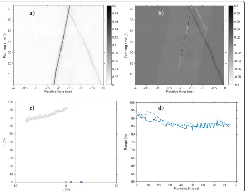
As an example, two moving sources are present in this experiment: one is the same boat whose trajectory is known based on its GPS, and the other is an unknown boat moving at a high speed. In processing, the second boat is considered the jamming source. The recorded waveforms are prefiltered the same as in Section 3 and processed in 0.5-s blocks. The two correlation outputs are displayed in Fig. 8a, corresponding to the jamming
source (dark curve) and target source (light curve). The relative delays of the jamming source indicate that it moves in the opposite direction of the target source. At a running time of approximately 68 s, the two sources are at the same position and thus have the same TDOA. Given the relative time delays of the interference align-ment, interference cancellation is performed on the PHAT output, yielding the result shown in Fig. 8b. The strong moving jamming source is eliminated, whereas the target source is retained. Some portions of the interference are not well isolated because of variations in the jamming source when it moves, as mentioned in Section 2.2.
The relative time delays of the target source on the re-ceiver pairs can then be obtained directly, even at a running time close to the crossing event. Finally, the localization re-sults are obtained, as shown in Fig. 8c, which agrees well with the GPS measurements in Fig. 8d.
The Radon transform works well for line detection. When the signal-to-interference ratio is very weak, a weak variation in the PHAT output exists at the crossing Relative time (ms)
-3 -2.5 -2 -1.5 -1 -0.5 0 0.5
Relative time (ms)
-3 -2.5 -2 -1.5 -1 -0.5 0 0.5
event, such that the target signal will be eliminated as well during the interference cancellation. Consequently, the trajectory of the target signal will be interrupted at the crossing event, causing a gap in the estimated time delays. Given that the wideband jamming source (mov-ing boat noise) has a good correlation function, the interference has only a slight influence on the TDOA estimation in the experiment. Nevertheless, this influ-ence is sufficient to show the efficacy of the proposed method. If the jamming signal does not have a sharp correlation peak, this method may be more applicable.
5 Conclusions
In passive localization, the target signal is significantly contaminated by strong interference. As a result, trad-itional localization methods may be ineffective. In this study, a hybrid method involving PHAT processing, interference cancellation, and position searching is pro-posed. By certain additional preprocessing of the PHAT
outputs, the interference can be adequately suppressed, allowing for good localization results in the preliminary experiments.
Although the experimental range is not the main con-cern of this study, the localization method can also achieve good performance at farther distances. A large system aperture is expected in that case, such as a long-baseline sensor array to achieve better localization. Furthermore, joint estimation is suggested for multiple localization sys-tems when the number of receivers is more than three.
One possible application of this method is the moni-toring of multiple moving acoustic sources with fixed hydrophones. A factor that is likely to impact the per-formance of this method is strong variation in the inter-ference. This problem may be solved by applying a constant strength to the PHAT output setting over an appropriate threshold. In the experimental investigation, only direct arrival signals are considered. However, multipath propagation may not be negligible at longer
Relative time (ms)
-4 -3.5 -3 -2.5 -2 -1.5 -1 -0.5 0
Relative time (ms)
-4 -3.5 -3 -2.5 -2 -1.5 -1 -0.5 0
ranges. Thus, a ray model may be necessary for time-delay estimation. A possible method to address this issue is to replace the analytical partial derivatives by a numerical method; however, this may require substantial computa-tional resources.
Acknowledgements
The authors gratefully acknowledge the support for this research by the National Natural Science Foundation of China (61571366) and Natural Science Basic Research Plan in Shaanxi Province of China (2015JQ5199).
Competing interests
The authors declare that they have no competing interests.
Received: 23 June 2016 Accepted: 25 November 2016
References
1. JBY Tsui, Fundamentals of global positioning system receivers. (Wiley-Interscience, New York, 2000). doi:10.1002/0471200549
2. WK Ma, BN Vo, SS Singh, A Baddeley, Tracking an unknown time-varying number of speakers using TDOA measurements: a random finite set approach. IEEE Trans. Signal Process.54(9), 3291–3304 (2006). doi:10.1109/TSP.2006.877658 3. NH Lehmann, AM Haimovich, RS Blum, L Cimini,Proc. Fortieth Asilomar
Conference on Signals, Systems and Computers. High resolution capabilities of
MIMO radar, 2006. doi:10.1109/ACSSC.2006.356576
4. M Bruno, KW Chung, H Salloum, A Sedunov, N Sedunov, A Sutin, H Graber,
P Mallas, in Waterside Security Conference (WSS), 2010. doi:10.1109/WSSC.
2010.5730229. Concurrent use of satellite imaging and passive acoustics for maritime domain awareness
5. J Gebbie, M Siderius, R McCargar, JS Allen III, G Pusey, Localization of a noisy broadband surface target using time differences of multipath arrivals. J. Acoust. Soc. Am.134(1), EL77–EL83 (2013). doi:10.1121/1.4809771 6. CH Knapp, GC Carter, The generalized correlation method for estimation of
time delay. IEEE Trans. Acoust. Speech Signal Process.24(4), 320–327 (1976). doi:10.1109/TASSP.1976.1162830
7. B Qin, H Zhang, Q Fu, Y Yan,Proc. 9th Int. Conf. on Signal Processing.
Subsample time delay estimation via improved GCC PHAT algorithm, 2008.
doi:10.1109/ICOSP.2008.4697676
8. MS Brandstein, HF Silverman,Proc. IEEE Int. Conf. Acoust. Speech, Signal Process. A robust method for speech signal time-delay estimation inreverberant
rooms, 1997. doi:10.1109/ICASSP.1997.599651
9. J Chen, J Benesty, Y Huang, Time delay estimation in room acoustic environments: an overview. EURASIP J. Appl. Signal Processing.170, (2006). doi:10.1155/ASP/2006/26503
10. DJ Torrieri, inAutonomous robot vehicles, ed. by IJ Cox, GT Wilfong (Springer, New York, 1990), pp. 151–166
11. YT Chan, KC Ho, A simple and efficient estimator for hyperbolic location. IEEE Trans. Signal Process.42(8), 1905–1915 (1994). doi:10.1109/78.301830 12. DP Young, CM Keller, DW Bliss, KW Forsythe,Proc. 37th Asilomar Conf. Signals,
Syst. Comput. Ultra-wideband (UWB) transmitter location using time difference of
arrival (TDOA) techniques, 2003. doi:10.1109/ACSSC.2003.1292184
13. KW Lui, FKW Chan, HC So, Accurate time delay estimation based passive localization. Signal Processing89(9), 1835–1838 (2009). doi:10.1016/j. sigpro.2009.03.009
14. B Friedlander, Accuracy of source localization using multipath delays. IEEE Trans. Aerosp. Electron. Syst.24(4), 346–359 (1988). doi:10.1109/7.7176 15. P Felisberto, O Rodriguez, P Santos, E Ey, SM Jesus, Experimental results of
underwater cooperative source localization using a single acoustic vector sensor. Sensors (Basel)13(7), 8856–8878 (2013). doi:10.3390/s130708856 16. NY Ko, TG Kim, YS Moon,Proc. OCEANS Int. Conf. Particle filter approach for
localization of an underwater robot using time difference of arrival, 2012.
doi:10.1109/OCEANS-Yeosu.2012.6263573
17. J Gebbie, M Siderius, JS Allen III, A two-hydrophone range and bearing localization algorithm with performance analysis. J. Acoust. Soc. Am.137(3), 1586–1597 (2015). doi:10.1121/1.4906835
18. F Antonacci, D Riva, D Saiu, A Sarti, M Tagliasacchi, S Tubaro,Proc. 14th European Signal Processing Conference, Tracking multiple acoustic sources
using particle filtering, 2006
19. HM Shertukde, Y Bar-Shalom, Detection and estimation for multiple targets with two omnidirectional sensors in the presence of false measurements. IEEE Trans. Acoust. Speech Signal Process.38(5), 749–763 (1990). doi:10.1109/29.56019
20. H Gauvrit, JP Le Cadre, C Jauffret, A formulation of multitarget tracking as an incomplete data problem. IEEE Trans. Aerosp. Electron. Syst.33(4), 1242–1257 (1997). doi:10.1109/7.625121
21. A.P. Dempster, N.M. Laird, D.B. Rubin, Maximum likelihood from incomplete data via the EM algorithm. J. R. Stat. Soc. Ser. B.39(1), 1–38 (1977). 22. D Carevic, Automatic estimation of multiple target positions and velocities
using passive TDOA measurements of transients. IEEE Trans. Signal Process.
55(2), 424–436 (2007). doi:10.1109/TSP.2006.885745
23. SR Deans,The Radon transform and some of its applications(Dover Publication, New York, 2007)
24. G Beylkin, Discrete radon transform. IEEE Trans. Acoust. Speech Signal Process.35(2), 162–172 (1987). doi:10.1109/TASSP.1987.1165108 25. MB Porter, Gaussian beam tracing for computing ocean acoustic fields. J.
Acoust. Soc. Am.82(4), 1349 (1987). doi:10.1121/1.395269
26. M.B. Porter, The BELLHOP manual and user’s guide: PRELIMINARY DRAFT. http://oalib.hlsresearch.com/Rays/HLS-2010-1.pdf. Accessed 1 Mar 2011.
Submit your manuscript to a
journal and benefi t from:
7Convenient online submission
7Rigorous peer review
7Immediate publication on acceptance
7Open access: articles freely available online
7High visibility within the fi eld
7Retaining the copyright to your article