R E S E A R C H
Open Access
Paramorphic multicarrier
communications for interference mitigation
Matt Carrick
1*, Jeffrey H. Reed
1and Chad M. Spooner
2Abstract
This paper presents a novel method for enabling communication in cyclostationary interference limited environments by adaptively inserting and exploiting spectral redundancy in an orthogonal frequency division multiplexing (OFDM) signal. The redundancy is formed through repeating data symbols across OFDM symbols in both time and frequency. A novel frequency shift (FRESH) filter is applied to exploit the time-varying cyclostationary properties, enabling the communication while under interference.
The ability to design an interference mitigating property into the communication signal creates a new degree of freedom when optimizing and adapting a waveform’s parameters. Simulation results demonstrate the performance gains in both signal to interference and noise ratio (SINR) and bit error rate (BER) as compared to traditional
time-invariant optimal filtering techniques and error correcting codes (ECC).
Keywords: FRESH filter, Cyclostationary, Spectral redundancy, Interference mitigation, Waveform optimization, Paramorphic waveform
1 Introduction
This paper proposes a method where spectral redundancy is adaptively designed into a multicarrier signal for com-municating in cyclostationary (CS) interference limited environments. Investing into redundancies within a signal to produce a gain at the receiver is a common trade-off in wireless communication system design. Common exam-ples of this trade-off include trading bandwidth for robust-ness by using coding to improve the bit error rate and using a larger cyclic prefix on an orthogonal frequency division multiplexing (OFDM) signal to improve the signal to noise ratio (SNR) at the receiver. These two solutions overcome traditional problems in wireless communica-tions: communicating in noise limited environments and the affects of multipath channels. This paper focuses on the separate but related problem of communicating within cyclostationary interference limited environments, where other communication signals are directly in-band of the desired signal. Simulation results demonstrate that under the given interference scenarios, transmitting redundant spectra at selected positions in the overall spectrum and
*Correspondence: [email protected]
1Bradley Department of Electrical and Computer Engineering, Virginia Polytechnic and State University, Blacksburg, Virginia, 24061, USA Full list of author information is available at the end of the article
optimally combining it at the receiver enables reliable communication which is otherwise not possible using error correcting codes alone.
The novelty of the proposed method includes:
• Implements a method for communicating in cyclostationary interference limited environments. • Adaptable and dynamic and adjusts the waveform
parameters and locations of redundancies to the spectral environment on the fly.
• Implements a novel filter for exploiting time-varying cyclostationary properties of signals.
• Provides more than 16.5 dB worth of SNR gain at a BER of10−5within the given simulation as compared to low density parity check (LDPC) error correcting codes.
The proposed method introduces redundancies into the signal, analogous to an error correcting code (ECC). The proposed method is explicitly designed for cyclostation-ary interference, in direct contrast to ECCs which are designed for stationary noise. The performance of ECCs degrades quickly under wideband cyclostationary
ference because these assumptions are not valid; however, the paramorphic waveform is much more robust under the same conditions because it is specifically designed for the signal environment at hand.
A FRESH filter is applied to mitigate the interference and collapse the expanded bandwidth down to its nomi-nal value, anomi-nalogous to a direct-sequence spread spectrum (DSSS) receiver. The bandwidth expansion of the DSSS signal is fixed, a function of the spreading sequence. The distribution of the signal energy is inefficient as it is smeared across the spectrum due to the spreading oper-ation, requiring bandwidth expansion factors of 15 or 31 for short code DSSS [1]. The proposed technique only requires a bandwidth expansion factor of K to mitigate the impact of K −1 full bandwidth interferers because the redundancies are optimally combined at the receiver [2]. The method allows for more flexibility, placing redun-dancies across the spectrum with finer detail and adapt-ing their location and power levels accordadapt-ing to the interference.
Simulated annealing is used to optimize the waveform parameters in light of the interference rejection capabil-ity, balancing the improved BER with the reduction in spectral efficiency, approximating an optimal solution to a non-linear multi-objective optimization problem.
Multicarrier waveforms designed with spectral redun-dancy are referred to as paramorphic 1 multicarrier waveforms (PMW), requiring new adaptive demodula-tors to incorporate the redundancy into the estimate of the desired signal, referred to as paramorphic FRESH demodulators(PFD).
1.1 Related work
A comparison between various interference mitigation techniques and FRESH filtering is described, followed by the related contributions within FRESH filtering, and finally, the contributions of the proposed method are described in relation to the existing literature.
FRESH filtering occupies two overlapping, but distinct fields: adaptive filtering and cyclostationary signal pro-cessing. The FRESH filter exploits the cyclostationary properties of signals and does so through the use of adap-tive periodically time varying (PTV) filtering, making it well suited for interference mitigation [2]. It can be con-sidered as supplementing existing methods, as it is a more general case of the optimal time invariant (TI) filter [2, 3]. FRESH filters, being PTV filters, outperform their TI counterparts at the cost of additional filtering complexity. As FRESH filters exploit spectral redundancies, they are broadly applicable. This includes further improving the interference mitigation properties of DSSS [4] and array processing systems [5]. A more in-depth discussion of the advantages and disadvantages of FRESH filtering can be found in [6, 7].
There has been much research on CS signals and their processing [6] with the most recent interest being in the applications to OFDM and multicarrier signals [7]. The theory of optimal periodically time-varying filtering for CS signals was proposed in [8], which would later become known as FRESH filtering [2]. Frequency-domain FRESH filtering was developed in [9] and the adaptation of such structures in [10, 11]. Improving the CS features of OFDM signals has been proposed in [12, 13] for network identi-fication and cognitive radio applications. In [13, 14], the cyclostationarity of an OFDM signal is incorporated by repeating symbols in frequency and time, respectively, for the purpose of user network identification. The use of FRESH filtering to exploit the spectral redundancy of CS OFDM signals is suggested in [15] but not explored any further. The use of FRESH filtering to exploit the spectral redundancy in OFDM signals induced by the cyclic prefix is proposed in [16, 17].
A time-varying FRESH (TV-FRESH) filter was first pre-sented in [18] to exploit time-varying cyclostationary in OFDM signals and mitigate wideband interference, while [19] demonstrated the applicability for improving equal-ization in generalized frequency division multiplexing (GFDM) signals [19]. The TV-FRESH filter was also used in [20] for mitigating the interference radar signals to OFDM.
This paper distinguishes with respect to the existing lit-erature itself by presenting a system for designing and adapting the cyclostationary properties of OFDM sig-nals for interference mitigation. The paramorphic method expands upon [2, 8–11, 16, 17] by proposing a frequency domain filter which exploits time-varying cyclostationary features. Additionally, the proposed method utilizes the cyclostationarity of OFDM for improving the robustness of communications, where [12–14] focused on network identification.
1.2 Outline
The remainder of the paper is outlined as follows. Section 2 provides relevant background information on cyclostationary signals, FRESH filtering, and simu-lated annealing. In Section 3, the proposed approach is described, including the signal model, improved demod-ulator and its optimal weights, and the optimization of the waveform design and demodulator. Section 4 presents simulation results and a complexity analysis, and Section 5 concludes the paper.
2 Background
and their relevant properties are described in Section 2.2. The FRESH filtering structure and the derivation of its minimum mean squared error (MMSE) filter weights is given in Section 2.3, and an introduction to simulated annealing is presented in Section 2.4.
2.1 Received signal model
The received signal model used within this paper is described by:
x(t)=(d(t)⊗φ(t))+(ψ(t)⊗i(t))+n(t), (1)
wherex(t)is the received signal,d(t)is the desired signal and its channel isφ(t),i(t)is the CS interference and its channel isψ(t), andn(t)is the stationary white noise. The convolution operator is represented by⊗, defined as:
a(t)⊗b(t)=
∞
−∞a(τ)b(t−τ)dτ. (2)
The analytic expressions in the remainder of this paper often use the frequency domain representation, which is given by:
X(f)=D(f)(f)+I(f)(f)+N(f), (3)
whereX(f)=F{x(t)}. 2.2 Cyclostationary signals
Cyclostationary signals are those which contain second-order periodicity in the time domain and spectral redun-dancy in the frequency domain. The spectral correlation density function,Sαx(f), given in (4) [21], is a measure of spectral redundancy at CFα[2], andXT(t,f)is the
short-time Fourier transform (5) of the signal x(t). A CF is a relative difference in frequency for which the signalx(t)
spectrally correlates with itself,Sαx(f)=0,
Cyclostationary signals may also exhibit conjugate spec-tral correlation,Sβxx∗(f) = 0, of whichβ is a conjugate
one CF,α =0, and there may be multiple CFs present in one signal.
2.3 FRESH filtering
A FRESH filter is the optimal widely linear filter for CS signals [2]. It exploits spectrally redundant information in its input to produce an estimate of the desired signal. The received signal is filtered through a parallel set of FSs followed by linear time-invariant filters, and the results are summed. Both the spectral redundancy and conju-gate spectral redundancies are exploited as they contain redundant information and should be used to produce a better estimate of the desired signal. The FRESH filter is defined in (7) [2], and MandN are the number of FSs corresponding to the spectral correlation and conjugate spectral correlation. The FRESH filter (7) is illustrated schematically in Fig. 1, second-order periodicities withinx(t)from their CF dif-ferences which can be exploited by the FRESH filter [2]. The set of CFs corresponding to the desired signal is given by{γd} = {γd,0,γd,1,γd,2, . . .}, and the set for the
inter-ference is given by{γi} = {γi,0,γi,1,γi,2, . . .}. The set of all
FSs{α}is therefore:
{α} = {γd,0, γd,1, γd,2, . . .,
and{α}does not have to be ordered in a specific manner. The set{β}is formed similarly. If{ζd}is the set of CFs of
the conjugate spectral redundancy for the desired signal, and{ζi}for the interference, then:
Both (8) and (9) represent the sets of all cycle frequen-cies corresponding to the spectral redundancy and con-jugate spectral redundancy. Both the desired signal and interference can have multiple cycle frequencies present, and the received signal contains combinations of the sums and differences of the cycle frequencies. Thus, the sets (8) and (9) represent all of the cycle frequencies of the received signal.
The FSsej2παmtalign the spectral redundancies within
x(t), which are then combined using the filters am(t).
Similarly, the FSs ej2πβnt align the conjugate spectral redundancies withinx∗(t), which are combined using the filtersbn(t).
One method for determining the optimal filtersam(t)
andbn(t) is to minimize the mean squared error (MSE)
produced by the FRESH filter, where the error is the dif-ference between the desired signald(t)and its estimate,
˘
d(t). Finding the filter weights which minimize the MSE is simpler mathematically in the frequency domain; there-fore, the filter estimate F{˘d(t)} is transformed into the
first step in finding the filter weights corresponding to the MMSE is forming the filter error and then the MSE. The filter errorE(f)is given by (11), whereF{d(t)} = D(f).
The MSE of (12) can be found by taking its derivative and setting equal to zero. The derivative of the MSE is done with respect to the filter weights Am(f) andBn(f),
the frequency domain versions of the filters in (7). To find the filters Am(f) andBn(f) that minimize the
MSE, the derivative of the MSE is taken with respect to both sets of filters and set equal to zero as in (13) and (14),
∂EMSE(f)
∂A∗m(f) =0, (13)
∂EMSE(f)
∂B∗n(f) =0. (14)
Performing the derivatives of the MSE results in two orthogonal projections as expected for a MMSE filter, (15) and (16). The projections state that the filter errorE(f)is orthogonal to the inputX(f)andX∗(f)at each of the FSs,
EE(f)X∗f −αm =0, (15)
EE(f)X−f +βn =0. (16)
The filter errorE(f)(11) is substituted into the orthogo-nal projections (15) and (16), resulting in the FRESH filter design equations in [2],
2.4 Simulated annealing
Simulated annealing [22] is a meta-heuristic optimization approach that has been applied to cognitive radio [23]. Simulated annealing derives its technique from metal-lurgy, where the temperature of a metal is high while being shaped and is gradually cooled as it takes its final shape. In our context, this process is simulated by testing a series of candidate solutions (heating and forging), measuring their performance, and gradually narrowing down the scope of potential solutions over time (cooling). To avoid focusing on a local maxima, simulated annealing uses a probabilis-tic function to determine if a solution with relatively worse performance will be accepted. Over time, this probabil-ity is decreased, allowing the algorithm to find the global maximum.
Simulated annealing is used in Section 3 to optimize the waveform parameters which minimize the BER while maximizing the spectral efficiency, subject to an objec-tive function. The multi-objecobjec-tive non-linear optimiza-tion problem makes deriving an analytic soluoptimiza-tion difficult, and therefore, simulated annealing is used to approximate the optimal solutions.
3 Paramorphic multicarrier waveform and
demodulator
We propose to insert spectral redundancy into an OFDM signal through data-symbol repetition to form a paramorphic multicarrier waveform. A paramorphic FRESH demodulator is then developed to exploit the time-varying spectral redundancy designed into the sig-nal. A signal model is created in Section 3.1 to describe the nature of the symbol repetition, and the resulting CS properties are described in Section 3.2. The novel demodulator which exploits the time-varying spectral redundancy is proposed in Section 3.4 and its MMSE fil-ter weights are derived in Section 3.5. The theoretical SINR at the output of the novel FRESH filter is derived in Section 3.6, and a joint optimization is proposed in Section 3.7 to select the best operating parameters of the new paramorphic waveform.
3.1 Signal model
The standard OFDM signal model is provided and adapted to include symbol repetition that creates exploitable spectral redundancy. An OFDM signal withN
subcarriers is represented by (19) and (20) in the time and frequency domains, respectively [13]:
In these modelsal,nis the data-symbol of thelthOFDM
symbol applied to subcarriernandq(t)is the rectangu-lar pulse shape, whereQ(f) = F{q(t)}. T is the length of the window, including the cyclic prefix time, where
T =TCP+Ts.
The OFDM model in (19) and (20) is modified by incor-porating data-symbol repetition across both time and fre-quency, requiring block-based transmissions ofBOFDM symbols. The data-symbols to be transmitted within each block are represented byal,0,al,1,. . .,al,M−1, and themth
symbolal,mis repeatedR(m)times within the block. The
data-symbol al,m is mapped onto the subcarrier at
fre-quencyfm,rwherer=0, 1,. . .,R(m)−1. The signal model for the cth OFDM symbol within the lth block for the
proposed technique is therefore [18]:
dl,c(t)=
The symbols al,n of (19) are typically assumed to be
independent and identically distributed (IID) [24, 25]. The symbols applied to the subcarriers are no longer indepen-dent, as correlation has been introduced into the signal by design in (21). 3.2 Cycle frequencies of paramorphic waveform
The cycle frequencies of the received signal must be known to the receiver when constructing the PFD. As in (8) and (9), the cycle frequencies come from the desired signal and the interference. In this section, the cycle fre-quencies of the desired signal are described, while the cycle frequencies of the interference are described in Section 3.3.
The PMW is able to independently select any linear modulation format on each of its subcarriers; however, the type of modulation will have an impact on the cyclosta-tionary properties of the signal. Formats such as quadra-ture amplitude modulation (QAM) and phase shift keying (PSK) will induce spectral redundancy when their symbols are repeated across the spectrum, while others such as pulse amplitude modulation (PAM) and binary phase shift keying (BPSK) in addition will induce conjugate spectral redundancy. The impact of these formats are highlighted here because they are commonly used, but it does not preclude the use of other constellations.
The CFs corresponding to the repetitions of symbolal,m
which is derived from the repetition patterns of the data-symbols, can be exploited. Examples of repetition patterns are given in Figs. 2 and 3.
While repeating data-symbols creates spectral redun-dancy, some modulations have inherent conjugate spec-tral redundancy which can also be exploited. The test for spectral redundancy is given by [26]:
E{vv∗} =0, (23)
and the test for conjugate spectral redundancy is given by:
E{vv} =0, (24)
wherevis the set of all constellation points within a modu-lation. A modulation format contains spectral redundancy when (23) is true and and conjugate spectral redundancy when (24) is true.
For QPSK,v= {−1−j,−1+j, 1−j, 1+j}, and from (23),
E{| −1−j|2+ | −1+j|2+ |1−j|2+ |1+j|2} =0, (25)
and according to (24),
E{(−1−j)2+(−1+j)2+(1−j)2+(1+j)2} =0, (26)
therefore, it only contains spectral redundancy. For BPSK,
E{(−1)2+(1)2} = 0 and E{| −1|2+ |1|2} = 0; thus, it has both spectral correlation and conjugate spectral correlation. Other modulations can be tested for spectral redundancy and conjugate spectral redundancy by apply-ing (23) and (24). Once the type of redundancy is known, its cycle frequencies can be incorporated into the PFD as in (31) and (32).
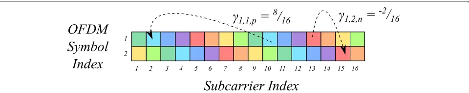
The CFs are therefore defined according to the mod-ulation and their location within the repetition pattern. As data-symbols can be repeated in time, new notation is needed to capture the now time-varying spectral redun-dancy. The notation γc,b,u is described in Fig. 2,
show-ing how the cycle frequencies align spectral redundan-cies in time. For example, γ2,1,k frequency shifts OFDM
symbol 1 to align the redundancies in OFDM sym-bol 2. The k index represents the kth cycle frequency between OFDM symbol 1 and 2. The same is true for
ζc,b,v which represents the CFs of the conjugate spectral
redundancy.
There is a trade-off when selecting the modulation for-mat for each of the subcarriers. QAM has a better BER than PAM for the same modulation order under station-ary white noise [1]; however, PAM includes conjugate spectral redundancy which can be incorporated into the PFD for a signal processing gain over using QAM. The selection of the modulation format for each of the subcar-riers is dependent on the requirements for the communi-cation link and the characteristics of the received signal including the type and parameters of the interference and the SNR. The optimization in Section 4.5 provides one set of results where these trade-offs are incorporated by minimizing the BER while maximizing the spectral redundancy.
3.3 Interference model
A single carrier 16-QAM signal is used as interference to show the ability of the PFD to mitigate wideband hetero-geneous interference. The analytic representation for the interference is [1]:
i(t)= +∞
k=−∞
skp(t−kT)ej2πf0t, (27)
where sk is the kth 16-QAM symbol and p(t) is a
square root raised cosine (SRRC) pulse-shaping filter with roll-off factor 0.35 and f0 is the center frequency of the signal. Specific parameters for the interference such as the power and bandwidth are specified in Section 4.1.
The cycle frequencies of a 16-QAM signal are [26]:
α= k
T, k=0,±1,±2, . . . . (28)
Fig. 2Spectral redundancy is distributed across both time and frequency within this pattern ofB=2 OFDM symbols,N=16 subcarriers, and
Fig. 3An example of a repetition pattern forB=4 OFDM symbols,N=16 subcarriers, andM=8 data-symbols
The SRRC pulse shaping reduces the energy of the spectral copies beyond the symbol rate; therefore, for practicality, the cycle frequencies are limited to:
α=
0,1
T,−
1
T
. (29)
3.4 Paramorphic FRESH demodulator
The analytic representation of the PFD is given in this section. The PFD structure only requires knowledge of the cycle frequencies within the received signal as in (31) and (32). The cycle frequencies αc,b,u and βc,b,u
deter-mine how many filtering branches are located within the PFD. The cycle frequencies of the PMW can be deter-mined from Section 3.2 and the cycle frequencies of the interference from Section 3.3. The additional knowl-edge required for MMSE filter weights is described in Section 3.5.
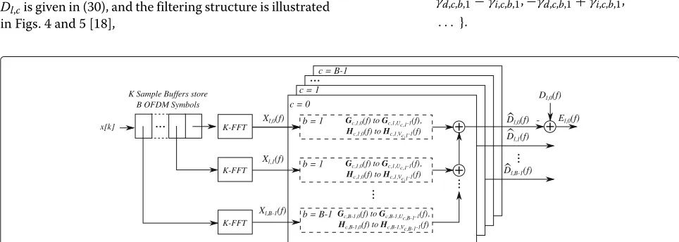
The fast Fourier transform (FFT) is used to demodulate the OFDM signal, transforming the time domain signal into frequency domain symbols. A novel FRESH filter is employed in the frequency domain to exploit the time-varying spectral redundancy of the received signal. Each block ofBOFDM symbols are buffered in memory using a series of delay lines which allows them to be jointly fil-tered. The estimateDˆl,cof thecthsymbol of thelthblock Dl,cis given in (30), and the filtering structure is illustrated
in Figs. 4 and 5 [18],
ˆ Dl,c(f)=
B−1
b=0
⎛ ⎝Uc,b−1
u=0
Gc,b,u(f)Xl,b
f−αc,b,u
+ Vc,b−1
v=0
Hc,b,v(f)Xl,b∗
−f +βc,b,v
⎞
⎠.
(30)
Uc,b is the number of FSs in the FRESH filter
between OFDM symbol c and OFDM symbol b. Similarly, Vc,b is the number of FSs in the FRESH
filter corresponding to the conjugate spectrally redundant symbols in OFDM symbol c and OFDM symbolb.
The estimate of the PMW (30) is a function of the FSs {αc,b,u}and{βc,b,v}in the FRESH filter. The set of CFs of
the spectral correlation for the PMW,{γd,c,b,u}, and
inter-ference,{γi,c,b,u}, as well as their differences are included in the set of FSs{αc,b,u}as in (8):
{αc,b,u} = {γd,c,b,0, γd,c,b,1, γd,c,b,2, . . . , γi,c,b,0, γi,c,b,1, γi,c,b,2, . . . , γd,c,b,0−γi,c,b,0,−γd,c,b,0+γi,c,b,0, γd,c,b,0−γi,c,b,1,−γd,c,b,0+γi,c,b,1,
. . . ,
γd,c,b,1−γi,c,b,0,−γd,c,b,1+γi,c,b,0, γd,c,b,1−γi,c,b,1,−γd,c,b,1+γi,c,b,1,
. . . }.
(31)
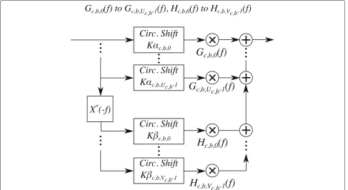
Fig. 5Each sub-filter is a linear combination of a series of frequency domain filters and circular shifts, which implement the FSs
The set of FSs{βc,b,v}is formed using the set of CFs of the conjugate spectral correlation for the PMW,{ζd,c,b,u},
and interference,{ζi,c,b,v}, and their differences: {βc,b,v} = {ζd,c,b,0, ζd,c,b,1, ζd,c,b,2, . . . ,
ζi,c,b,0, ζi,c,b,1, ζi,c,b,2, . . . , ζd,c,b,0−ζi,c,b,0,−ζd,c,b,0+ζi,c,b,0, ζd,c,b,0−ζi,c,b,1,−ζd,c,b,0+ζi,c,b,1,
. . .,
ζd,c,b,1−ζi,c,b,0,−ζd,c,b,1+ζi,c,b,0, ζd,c,b,1−ζi,c,b,1,−ζd,c,b,1+ζi,c,b,1,
. . .}.
(32)
It is assumed that the cycle frequencies, and thus the sig-naling rate, of the interference is known. This information can be arrived at through spectrum sensing, or if the inter-ference is a legacy user in a shared spectrum band it will already be known. Mismatches or errors in the estimated cycle frequencies and the true cycle frequencies due to real world impairments can be corrected through adaptive algorithms [27].
Spectrally redundant information which does not vary with time, either present in the PMW or the interfer-ence, can be included in (31) and (32) by setting the FSs appropriately. Consider the example of a single-carrier QPSK interferer with symbol period T, whose CFs are {0,±T1,±T2, . . .} [26]. The CFs do not vary with time,
thusγi,c,b,u = ∅whenc = b, andγi,c,b,0 = 0, γi,c,b,1 =
1
T, γi,c,b,2= −T1, . . ., forc=b. 3.5 MMSE filter weights
The MMSE filter weights for Gc,b,u(f) and Hc,b,u(f) of
the PFD from (30) are derived within this section. The MMSE filter weights are optimal as they require knowl-edge of the desired signal, a common assumption used in the Wiener filter [3] derivation and previous MMSE FRESH filter weight derivations [2, 28, 29]. The MMSE filter weights are derived to find an upper bound on the performance of the filtering which future work can use as a reference. LMS algorithms for FRESH filters such as [10, 11] can be incorporated to adapt the filter weights using preambles for training or blind adaptation [30], such as decision-directed training or property restoration, and whose performance can be measured against the MMSE filter weights derived here.
The derivation of the MMSE filter weights [18] for
Gc,b,u(f)andHc,b,v(f)of the paramorphic FRESH
demod-ulator proceeds in the same fashion as the derivation for the time-domain FRESH filter from Section 2.3. The filter error is established in (33) and the MSE in (34):
El,c(f)=Dl,c(f)− ˆDl,c(f), (33)
EMSE(f)=E
El,c(f)E∗l,c(f)
The MSE is minimized by taking its derivative with
Solving for the derivatives results in two orthogonal projections, (37) and (38):
EEl,c(f)Xl,p∗ f −αc,p,k =0, (37)
EEl,c(f)Xl,m
−f +βc,m,n =0. (38)
The first projection states that the filter error of the
cth OFDM symbol is orthogonal to the conjugate of the received pth OFDM symbol when frequency-shifted by
αc,p,k.
The frequency domain error (33) is then substituted into the projections (37) and (38) to produce the opti-mal filter design Eqs. (41) and (42). The design equations include new ways of representing the spectral correlation. For example,Sαdc,p,k
is the cross spectral
corre-lation of thecthdesired OFDM symbol from each block
with thepth received OFDM symbol from each block at
FSαc,p,k, represented by:
Sαdc,p,k
In order to validate the simulation results, the theoretical signal to interference and noise ratio (SINR) at the output of the PFD is derived. The theoretical SINR (40) for thecth
OFDM symbol is:
denominator is the MSE and is expanded in (46), with additional terms given in (47) and (48), and where is the real operator. The analytical SINR from (40) is used to validate the simulation results for the PFD in Section 4.
Sdαcc,,px,kpf−αc,p,k
3.7 Joint optimization of waveform and demodulator Cognitive radios most commonly adapt waveform param-eters such as transmit power, modulation type and order, and code rate and type to satisfy objectives of BER, throughput, and spectral efficiency [23, 31]. The ability to design the waveform for interference mitigation using symbol repetition allows for another degree of freedom within the optimization.
The fitness function is used to combine the performance of several objectives into a single number where a larger fitness function directly translates to a more suitable solu-tion to the optimizasolu-tion. In this approach, a linear fitness function (43),
φ =w1φ1+w2φ2, (43)
combines the objective of the BER,φ1, and the objective
of the spectral efficiency,φ2. The weightsw1andw2are
set such thatw1+w2=1. The objectivesφ,φ1, andφ2are
all bounded by [ 0, 1]. The objective functions for the BER and spectral efficiency are given by (44) and (45) [32]:
φ1=
BERT is a target BER, and BERM is the measured BER.
threshold when computing the fitness function. Knowl-edge of the desired signal is also needed in order to form the MMSE filter weights of the PFD. In practical systems, training sequences or pilot sequences are transmitted to provide a known signal. The average information bits per symbol,η, comes from the modulation and incorporates the reduction in spectral efficiency due to coding as well as symbol repetition. The weights are set w1 = 23 and w2= 13to ensure the optimization does not select a
solu-tion which produces a poor BER but has an abnormally high spectral efficiency.
Simulation results are used to show the ability of the PMW and PFD to mitigate interference and make comparisons to traditional filtering techniques and ECC. The simulated scenario is motivated by the co-existence of 5G cellu-lar systems and satellite communications within the same band [33]. The SINR is used to compare against filtering techniques in Section 4.2, and the BER is used to compare
against ECCs in Section 4.3. Simulated annealing is used in Section 4.5 to optimize the BER and spectral efficiency when under interference. A detailed complexity analysis of the PFD is given in Section 4.6.
4.1 Simulation parameters
In Sections 4.2 and 4.3, five different techniques are compared for their ability to mitigate interference. The techniques are Wiener filtering, maximal ratio combin-ing (MRC), the proposed PFD, soft decision convolutional codes, and soft decision LDPC codes. The spectral redun-dancy of the interferer is exploited within the PFD results, but for no other methods. The LDPC codes used are those defined in the digital video broadcasting second gener-ation (DVB-S2) standard [34]. The SINR and BER are computed within the same set of Monte Carlo simula-tions. The length of the input signal to the FRESH filter is a minimum of 105samples for each run of the simulation, and the simulations continue until a minimum of 1000 bit errors are observed.
The 16-QAM interference model from Section 3.3 is used in all of the following simulations, although the power and bandwidth are varied. The interference has high SIR values within the passband of the desired sig-nal, and examples of the received spectrum under these conditions are given in Fig. 6a, b.
4.2 SINR performance
The SINR after the Wiener filter, MRC, and the PFD are all compared using the simulation parameters referenced in Section 4.1. The SINR is simulated for a series ofEb/N0
values where the interference to noise ratio is fixed at
Pi/N0 = 20 dB, and the interference bandwidth covers
1/2 and 1/4 of that of the OFDM signal. The energy per bit Eb/N0 is in relation to information bits, with QPSK
being used on each of the 64 subcarriers of the OFDM signal.
The SINR is plotted in Fig. 7a, b, and it can be seen that significant gains can be achieved by using the PFD over MRC and the Wiener filter. The gains over the Wiener filter are about 6 and 4 dB at Eb/N0 = 10 dB when
the interference covers 1/2 and 1/4 the PMW band-width. The gains over MRC are about 1.5 and 1 dB when the interference covers 1/2 and 1/4 the PMW bandwidth.
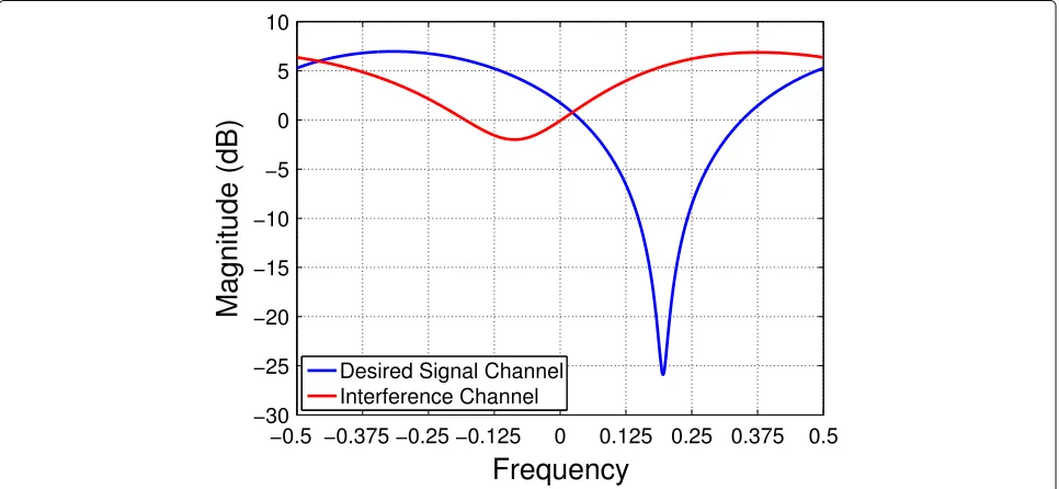
Fig. 6Two plots showing the spectrum of the received signal whenEb/N0=7 dB andPi/N0= 20 dB. The blue line represents the desired signal, and the red line represents the interference.aAn example of the spectrum when theinterference covers 1/2 of the bandwidth.bAn example of the spectrum when the interference covers 1/4 of the bandwidth
4.3 BER versus desired signalEb/N0
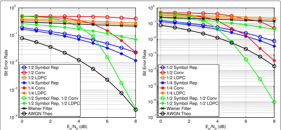
The results of the BER being simulated for the Wiener filter, PFD, convolutional coding, and LDPC are given in Fig. 8a, b using the simulation parameters and interference model of Section 4.1. For these results, the PMW uses QPSK on each of its 64 subcarriers, the interference power isPi/N0=20 dB and the bandwidth of the interference is
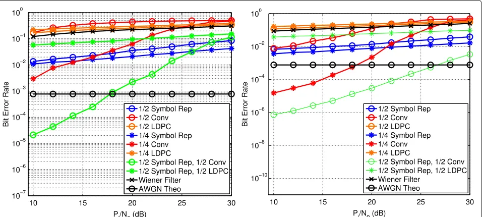
1/2 and 1/4 that of the PMW in Fig. 8a, b, respectively. The PFD outperforms both the Wiener filter, the LDPC, and the convolutional codes in these two scenarios due to its optimal combining of spectral redundancy, even with
only 1/2 rate symbol repetition. The PFD can improve the BER further by using 1/4 rate symbol repetition but with diminishing returns. Since the received signal is domi-nated by cyclostationary interference and not stationary noise, assumptions built into LDPC and convolutional codes break down and thus produce BERs of worse than 10−1for the considered values ofE
b/N0. However, using a
hybrid approach of the PFD and an ECC can improve the BER more than either method alone, by reducing the BER by 1000xin comparison to the next best method at high
Eb/N0values.
Fig. 8The BER curves comparing the performance of the 1/2 Rate Symbol Repetition PFD (blue circle), 1/4 Rate Symbol Repetition PFD (blue star), 1/2 Rate Convolutional Code (red circle), 1/4 Rate Convolutional Code (red star), 1/2 Rate LDPC (orange circle), 1/4 Rate LDPC (orange star), combined 1/2 Rate Symbol Repetition and 1/2 Rate Convolutional Code (green circle), combined 1/2 Rate Symbol Repetition and 1/2 Rate LDPC (green star), Wiener Filter (black x). The AWGN Theoretical is plotted with a black circle. All BER curves are plotted as a function ofEb/N0.a Bandwidth overlap of 1/2.bBandwidth overlap of 1/4
With the hybrid approach, the PFD is able to mitigate a large portion of the CS interference allowing the convo-lutional code to operate on the resulting signal which is mostly corrupted by stationary noise. It is for this reason that the hybrid approach exceeds the BER for the theo-retical AWGN curve in Fig. 8b. Enough CS interference is mitigated by the PFD that the convolutional code can then correct residual bit errors caused by the stationary noise.
The received signal is dominated by cyclostationary interference, and the time-varying nature of the PFD transforms the stationary white noise into time-varying noise. Additionally, the frequency shifts within the PFD color the white noise within the signal. The resulting noise at the output of the PFD is now non-stationary, period-ically time-varying, and colored, and it will include any remaining cyclostationary interference that was unable to be removed by the PFD. All of these qualities severely vio-late the assumptions of stationary white Gaussian noise built into the standard BER equations, which accounts for the distance between the theoretical BER curves and the Monte Carlo results. The violation of the assumptions also prevent an approximation of the theoretical BER by using the SINR results obtained in Section 4.2.
The expected reason for the bad performance of LDPC codes comes from the shape of the BER curve, or the thresholding effect. While above this threshold, LDPC codes perform well in AWGN, but below it, the codes pro-vide no error correction capability. In [35], it is shown that cyclostationary noise can have a dramatic effect on the
performance of LDPC codes at much smaller interference powers than what has been simulated in this paper.
Figure 9a, b shows the BER when under frequency-selective fading; the magnitude of the frequency response is given in Fig. 10. The desired signal channel is(z) = (−0.35−1.06j)+(−0.84+0.69j)z−1+(0.03−0.01j)z−2
and the interference channel is(z)=(−0.004+0.09j)+ (−0.80 + 1.26j)z−1+ (0.02 − 0.74j)z−2. The delay z−1
is defined according to the sampling rate. The simulated results use a normalized sampling frequency, with the ratio of the bandwidth of the PMW to the sampling ratio being 12. The BER for the paramorphic approach actually improves relative to the case in which there is no fad-ing. The FRESH filter can be thought of as an improved fractionally spaced equalizer [2], providing resistance to the fading effects. Additionally, the interference channel reduces the power of the interference on its left side, effectively reducing the bandwidth of the interference. Therefore, both BER curves are close to the case in which the bandwidth only covers 1/4 of the bandwidth, Fig. 8b.
4.4 BER versus interference power
The impact of the interference power on the BER is given in Fig. 11a, b, as the bandwidth of the interference is 1/2 and 1/4 that of the desired signal, respectively. In these results, the power of the desired signal is held constant at
Eb/N0 = 7 dB with QPSK being used on each of the 64
Fig. 9The BER curves of the filtering methods and error correcting codes while under Rayleigh fading. The BER curves include simulated results for 1/2 Rate Symbol Repetition PFD (blue circle), 1/4 Rate Symbol Repetition PFD (blue star), 1/2 Rate Convolutional Code (red circle), 1/4 Rate Convolutional Code (red star), 1/2 Rate LDPC (orange circle), 1/4 Rate LDPC (orange star), combined 1/2 Rate Symbol Repetition and 1/2 Rate Convolutional Code (green circle), combined 1/2 Rate Symbol Repetition and 1/2 Rate LDPC (green star), Wiener Filter (black x). The AWGN Theoretical is plotted with a black circle.aBandwidth overlap of 1/2.bBandwidth overlap of 1/4
degradation but the PFD has the most graceful degrada-tion, reducing the BER by less than an order of magnitude as the interference power is increased by 20 dB.
The hybrid approach of using the PFD and a convo-lutional code works better than each approach alone for almost all interference power values. The PFD is resilient to the increases in interference power and mitigates enough of the CS interference that the convolutional code
can be used to correct the bit errors caused by the resid-ual noise. This results in the hybrid approach producing a better BER that also degrades slowly as a function of interference power.
The results demonstrate how an adaptive approach can be beneficial as the spectral environment changes. The PMW and PFD perform well in strong, wideband interfer-ence but do not perform as well as ECCs in purely AWGN
Fig. 11The BER curves of the symbol repetition and filtering methods as a function of interference to noise power Pi/N0 when Eb/N0 = 7 dB. The methods compared are 1/2 Rate Symbol Repetition PFD (blue circle), 1/4 Rate Symbol Repetition PFD (blue star), 1/2 Rate Convolutional Code (red circle), 1/4 Rate Convolutional Code (red star), 1/2 Rate LDPC (orange circle), 1/4 Rate LDPC (orange star), combined 1/2 Rate Symbol Repetition and 1/2 Rate Convolutional Code (green circle), combined 1/2 Rate Symbol Repetition and 1/2 Rate LDPC (green star), Wiener Filter (black x). The AWGN Theoretical is plotted with a black circle.aBandwidth overlap of 1/2.bBandwidth overlap of 1/4
channels. Balancing the redundancy used within ECCs and symbol repetition can therefore maximize the spec-tral efficiency while minimizing the BER as the specspec-tral environment changes.
4.5 Optimization results
The optimization in Section 4.5 is used to maximize the spectral efficiency while minimizing the BER. The opti-mization of the PMW selects the symbol repetition rate, coding rate and modulation order for each of the 64 occu-pied subcarriers. The parameters of the 16-QAM interfer-ence described in Section 4.1 are used in this optimiza-tion, and it covers 1/2 of the OFDM signal bandwidth. The power of both the desired signal and interference are both fixed for SIR= −20 dB, along with a fixed SNR=10 dB. This leaves the selection of the waveform parameters as the only variables, which will also set theEb/N0.
The optimization is designed to meet the target BERs 10−1 to 10−5 while maximizing the spectral efficiency of the waveform. Each optimization is run for 500 iter-ations of the simulated annealing algorithm, and each iteration is run until 10 bit errors are simulated. Due to
computational and memory constraints within the sim-ulation, 16 occupied subcarriers are used and spectral redundancy is only used across a single OFDM symbol,
B= 1. The amplitude of each subcarrier is selected to be within (0, 1] , and Table 1 gives all options for the mod-ulations, symbol repetition and convolutional code rates available for selection.
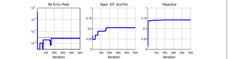
Figure 12 demonstrates how the simulated annealing algorithm balances the BER and the spectral efficiency to maximize the objective function. The initial iterations have the optimization looking for parameters which meet or exceed the target BER, and then, the spectral efficiency is improved through additional iterations. A record of the best set of outcomes is kept, which is represented by the blue line. The parameters which produced the maximum objective during the optimizations is given in Table 2. Table 3 contains the results of the optimizations when the symbol repetition is disabled.
Tables 2 and 3 list the parameters and outcomes for the optimizations. Each row lists the target BER, BERT, and
the measured BER, BERM. The symbol repetition rate and
the code rate for the convolutional codes is also given.
Table 1The list of options for the modulation, symbol repetition, and convolutional code rates from which the optimization can select
Modulations: BPSK, QPSK, 8-PSK, 16-PSK, 16-QAM
Symbol rep. rates: none, 1/2, 1/4, 1/8, 1/16
Fig. 12The BER, spectral efficiency, and objective per iteration for the simulated annealing algorithm with a target BER of 10−4
The average number of information bits per data-symbol is given, which takes into account the repetition rate and the modulation order of the data symbols. The spectral efficiency includes the average number of information bits per data-symbol and the code rate.
It is seen in Fig. 8a that using 1/2 rate symbol repetition provides the largest improvement in BER for the smallest amount of overhead, and a similar effect can be seen in Table 2. For the target BERs 10−1 to 10−4, the 1/2 rate symbol repetition is used, while for the BER 10−5, the 1/4 rate symbol repetition is needed to meet the BER.
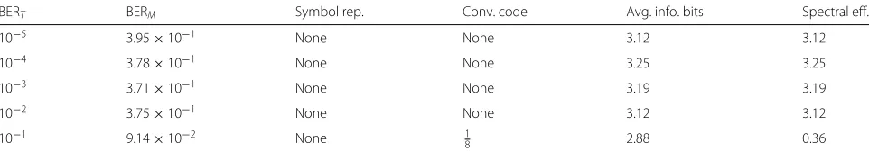
When the PMW and PFD is not used, the BER approaches 0.5 for most target BERs as seen in Table 3. As the BER cannot be controlled, the only way to maxi-mize the objective function is therefore to maximaxi-mize the spectral efficiency. The coding is able to meet the target BER for 10−1; however, its spectral efficiency is worse than
using the PFD as it requires a 18code to do so. The PMW and PFD provide 16.5, 12.3, 11.2, 11.0, and 10.7 dB worth of SNR gain from BERs 10−5to 10−1.
4.6 Complexity analysis
The improved performance of the PFD over traditional fil-tering methods comes at the cost of increased transform and filtering complexity, although clever design decisions can be made to minimize the complexity increases. A traditional FFT-based OFDM demodulator and one-tap equalizer is used as the baseline for comparison. The OFDM receiver discards the NCP samples of the cyclic prefix, transforms the remaining signal using anN-point
FFT, and then appliesNcomplex weights to the frequency domain samples. The increases to the complexity of the PFD due additional discrete Fourier transforms (DFT) is presented in Section 4.6.1, and the increases in complexity within the filtering operation is given in Section 4.6.2.
4.6.1 Complexity of additional DFTs
Traditional OFDM receivers discard the cyclic prefix before taking the FFT over the OFDM symbol. This creates distortion when the received signal is affected by a large-power interferer because it generates phase discon-tinuities, resulting in additional distortion. The increased complexity comes from taking a DFT over the entire OFDM symbol,N samples, along with the cyclic prefix
NCP samples, which allows the phase to remain
contin-uous. The additional complexity comes from this larger DFT, applying an IDFT to transform back to the time domain to discard the cyclic prefix after filtering, and a final FFT applied at the nominal size to obtain the frequency domain symbols.
The cyclic prefix length is often represented as a frac-tion of the number of samples within the body of the OFDM symbol,NCP =N/4 for example. Efficiently
com-puting the FFT requires a transform size that is a power of 2; however, the total input length ofN+NCP =5N/4
is unlikely to be a power of 2. In this case, another DFT implementation is needed.
It is more likely that the longer input sequence can be decomposed into two relative primes allowing use of the prime factorization algorithm (PFA) [36] to efficiently
Table 2The results from the simulated annealing optimization using the PMW and PFD approach
BERT BERM Symbol rep. Conv. code Avg. info. bits Spectral eff.
10−5 6.78×10⁻⁶ 1/4 3/5 0.88 0.53
10−4 8.86×10⁻⁵ 1/2 3/5 1.18 0.75
10−3 1.98×10⁻⁴ 1/2 5/9 1.50 0.83
10−2 5.21×10⁻³ 1/2 3/5 1.56 0.94
10−1 8.22×10⁻² 1/2 None 1.69 1.69
Table 3The results from the simulated annealing optimization without using the PMW and PFD approach
BERT BERM Symbol rep. Conv. code Avg. info. bits Spectral eff.
10−5 3.95×10⁻¹ None None 3.12 3.12
Avg. info. bitsis the average number of information bits per data symbol
implement the DFT. WhenN = 1024 andNCP = N/4, N +NCP = 1280 and can be factored into the relative primes of 256 and 5. Similarly, whenN=1024 andNCP= N/2,N+NCP=1536 and can be factored into the relative primes of 512 and 3. Although a closed-form expression does not exist for the complexity of the PFA, [36] lists the number of complex multiplies required for various trans-form sizes between 30 and 2520. From the given results, it can be generally stated that for large transform sizes,
N > 128, the number of complex multiplies required by the PFA for a transform of size 3N/2 requires about the same number of complex multiplies as the Radix-2 FFT of transform sizeN. The use of the PFA does not result in a substantial increase in complexity for a single transform and, in some circumstances, may decrease it.
The number of complex multiplies needed to imple-ment the Radix-2N-point FFT is [37]:
N
2log2(N). (49)
With the simplifying assumption that the PFA algorithm can implement theN+NCPsized DFT with approximately
the same number of multiplies as the Radix-2 N-point FFT, the relative increase complexity is approximately 3 times the number of multiplies required.
4.6.2 Complexity of filtering
Any FRESH filter, including the PFD, is able to exploit the cycle frequencies within the desired signal and any inter-ference, described by (31) and (32) of (30). Each frequency bin is now the summation of multiple complex weighted bins equivalent to the number of cycle frequencies over
BOFDM symbols. The redundant bins can be utilized to our advantage by avoiding duplicate work and only com-puting the summation of correlated bins for a set of cycle frequencies one time.
The maximum number of complex multiplies needed to execute the PFD is:
However, onlyN+Ncpof the frequency bins need to be
estimated due to the redundancies built into the signal. A
reasonable simplifying assumption is made that the num-ber of cycle frequencies is consistent across allBOFDM symbols:
multiplies to weight the redundant OFDM symbols and:
(N+NCP) (U+V)B, (54)
additions to perform the summation across the B OFDM symbols. The relative increase in complexity over the one-tap equalization to implement the filtering is therefore:
(N+NCP)
N (U+V), (55)
complex multiplies and:
(N+NCP)
N (U+V)B, (56)
complex additions. The relative complexity increase of (55) can be separate into two terms: N+NCP
N due to the
larger FFT size and U + V due to the exploitation of the spectral redundancies and conjugate spectral redun-dancies. The one-tap equalization uses NCP = 0 since
it discards the cyclic prefix before the FFT, andU = 1 and V = 0 because it does not exploit any spectral redundancies.
An example is provided to demonstrate the increase in complexity in using the PFD, or any FRESH filter, rela-tive to the one-tap equalizer. In this example, the PMW transmits QPSK data symbols which have been repeated twice, represented by 2 cycle frequencies, and the 16-QAM interferer of Section 3.3 uses 3 frequencies in (29); therefore,U = 5. Neither of the two signals have conju-gate spectral redundancy; therefore,V =0. WhenNCP=
N 4, then
N+NCP
N = 54. The relative increase in number of
5 Conclusions
A novel method has been proposed for creating interfer-ence mitigation properties in paramorphic multicarrier waveforms to enable communication in cyclostationary interference limited environments. Spectral redundancy is formed through repeating data symbols in both time and frequency within OFDM symbols, which is exploited at the receiver for a signal processing gain. The method provides a new way to design signals to be robust against cyclostationary interference, while simultaneously pro-ducing a better BER than ECCs for similar overhead rates under the simulated scenarios.
Future work would include using more generalized rep-etition patterns, both varying the amount of reprep-etition per symbol and its placement in time and frequency. The spectral redundancy could also be designed across mul-tiple antennas, including the development of the appro-priate array processing algorithms to exploit the spatially distributed spectral redundancy. A real-time cognitive engine could also be developed which takes into account the proposed waveform adaptation techniques.
Endnote
1The property of changing from one mineral species
to another (as from aragonite to calcite) by a change in internal structure and physical characters but not in chemical composition. “Paramorphism”, Def., Merriam-Webster, http://www.merriam-webster.com/dictionary/ paramorphism
Abbreviations
BER: Bit error rate; ECC: Error correcting code; CS: Cyclostationary signals; CF: Cycle frequency; DVB-S2: Digital video broadcasting second generation; FS: Frequency shift (within context of the operation); FRESH: Frequency shift (within context of the filtering structure); LDPC: Low density parity check; MMSE: Minimum mean squared error; MRC: Maximal ratio combining; PMW: Paramorphic multicarrier waveform; PFD: Paramorphic FRESH demodulator; SINR: Signal to interference and noise ratio; SNR: Signal to noise ratio; SIR: Signal to interference ratio; TV-FRESH: Time-varying FRESH
Funding
The work of M. Carrick and J. H. Reed was supported in part by the National Science Foundation under grant CNS-1564148.
Authors’ contributions
MC is the primary author of this paper, who developed the simulations and wrote the first draft of the paper. JHR has acted as his academic advisor through the duration, providing feedback at all levels. CMS provided substantial feedback on the whole manuscript, with a particular emphasis on the cyclostationary elements of the paper. All authors read and approved the final manuscript.
Competing interests
A patent has been submitted by M. Carrick and J. H. Reed covering materials in this manuscript, “Method for jointly adapting an OFDM waveform and the demodulator for interference mitigation and harsh channels,” Patent ID: 62144039
Publisher’s Note
Springer Nature remains neutral with regard to jurisdictional claims in published maps and institutional affiliations.
Author details
1Bradley Department of Electrical and Computer Engineering, Virginia
Polytechnic and State University, Blacksburg, Virginia, 24061, USA.2NorthWest
Research Associates, Monterey, California 93940, USA.
Received: 1 August 2017 Accepted: 18 December 2017
References
1. J Proakis,Digital Communications, 5th Edition. (McGraw Hill, New York, 2007)
2. WA Gardner, Cyclic Wiener filtering: theory and method. IEEE Trans. Commun.41(1), 151–163 (1993)
3. S Haykin,Adaptive Filter Theory. (Prentice-Hall, Inc., Englewood Cliffs, N.J., 2001)
4. V Aue, JH Reed, inIEEE Forty-Fourth Vehicular Technology Conference. An interference robust CDMA demodulator that uses spectral correlation properties (IEEE, 1994), pp. 563–567
5. P Petrus, JH Reed, Time dependent adaptive arrays. IEEE Signal Process. Lett.2(12), 219–222 (1995)
6. WA Gardner, A Napolitano, L Paura, Cyclostationarity: half a century of research. Signal Process.86(4), 639–697 (2006)
7. A Napolitano, Cyclostationarity: new trends and applications. Signal Process.120, 385–408 (2016)
8. W Gardner, L Franks, Characterization of cyclostationary random signal processes. IEEE Trans. Inf. Theory.21(1), 4–14 (1975)
9. E Ferrara, Frequency-domain implementations of periodically time-varying filters. IEEE Trans. Acoust. Speech Signal Process.33(4), 883–892 (1985)
10. JH Reed, TC Hsia, The performance of time-dependent adaptive filters for interference rejection. IEEE Trans. Acoust. Speech Signal Process.38(8), 1373–1385 (1990)
11. JH Reed, NM Yuen, TC Hsia, An optimal receiver using a time-dependent adaptive filter. IEEE Trans. Commun.43(2/3/4), 187–190 (1995) 12. K Maeda, A Benjebbour, T Asai, T Furuno, T Ohya,
Cyclostationarity-inducing transmission methods for recognition among OFDM-based systems. EURASIP J. Wireless Commun. Netw. Cognitive Radio Dynamic Spectrum Sharing Syst.2008(23), 1–14 (2008) 13. PD Sutton, KE Nolan, LE Doyle, Cyclostationary signatures in practical
cognitive radio applications. IEEE J. Selected Areas Commun.26(1), 13–24 (2008)
14. J Sun, D Qu, T Jiang, G Zhong, J Guo, in2011 IEEE Vehicular Technology Conference (VTC Fall). Low overhead cyclostationary signatures based on hopping subcarrier in OFDM-based dynamic spectrum access networks (IEEE, 2011), pp. 1–5
15. P Sutton, Rendezvous and coordination in OFDM-based dynamic spectrum access networks.PhD thesis, University of Dublin (2008) 16. J Tian, H Guo, H Hu, HH Chen, Frequency-shift filtering for OFDM systems
and its performance analysis. IEEE Syst. J.5(3), 314–320 (2011)
17. N Shlezinger, R Dabora, Frequency-shift filtering for OFDM signal recovery in narrowband power line communications. IEEE Trans. Commun.62(4), 1283–1295 (2014)
18. M Carrick, JH Reed, F harris, in2017 IEEE International Conference on Digital Signal Processing (DSP). An optimal filter for signals with time-varying cyclostationary statistics (IEEE, 2017), pp. 1–5
19. M Carrick, Reed JH, in2017 IEEE 38th Sarnoff Symposium. Improved GFDM equalization in severe frequency selective fading (IEEE, 2017), pp. 1–6 20. M Carrick, JH Reed, in2017 IEEE Global Conference on Signal and
Information Processing (GlobalSIP). Exploiting the cyclostationarity of radar chirp signals with time-varying filters (IEEE, 2017), pp. 1–4
21. WA Gardner, CM Spooner, Signal interception: performance advantages of cyclic-feature detectors. IEEE Trans. Commun.40(1), 149–159 (1992) 22. S Kirkpatrick, C Gelatt, M Vecchi, Optimization by simulated annealing.
Science.220(4598), 671–680 (1983)
23. A He, KK Bae, TR Newman, J Gaeddert, K Kim, R Menon, L Morales-Tirado, J Neel, Y Zhao, JH Reed, WH Tranter, A survey of artificial intelligence for cognitive radios. IEEE Trans. Vehicular Technol.59(4), 1578–1592 (2010) 24. E Serpedin, GB Giannakis, Blind channel identification and equalization
with modulation-induced cyclostationarity. IEEE Trans. Signal Process.
46(7), 1930–1944 (1998)
26. W Gardner, Spectral correlation of modulated signals: part I—analog modulation. IEEE Trans. Commun.35(6), 584–594 (1987)
27. OAY Ojeda, J Grajal, Adaptive-fresh filters for compensation of cycle-frequency errors. IEEE Trans. Signal Process.58(1), 1–10 (2010) 28. WA Gardner,Statistical Spectral Analysis, A Nonprobabilistic theory.
(Prentice-Hall, Inc., Englewood Cliffs, 1988)
29. WA Gardner, WA Brown, inTwenty-Third Asilomar Conference on Signals, Systems and Computers, 1989. Frequency-shift filtering theory for adaptive co-channel interference removal. vol. 2 (IEEE, 1989), pp. 562–567 30. J Zhang, KM Wong, ZQ Luo, PC Ching, Blind adaptive fresh filtering for
signal extraction. IEEE Trans. Signal Process.47(5), 1397–1402 (1999) 31. TC Clancy, M Norton, M Lichtman, inMILCOM 2013-2013 IEEE Military Communications Conference. Security challenges with LTE-advanced systems and military spectrum (IEEE, 2013), pp. 375–381
32. T Newman, Multiple objective fitness functions for cognitive radio adaptation.PhD thesis, University of Kansas (2008)
33. F Guidolin, Nekovee M, in2015 IEEE Globecom Workshops (GC Wkshps). Investigating spectrum sharing between 5g millimeter wave networks and fixed satellite systems (IEEE, 2015), pp. 1–7
34. European Telecommunications Standards Institute. Digital Video Broadcasting (DVB); second generation framing structure, channel coding and modulation systems for broadcasting, interactive services, news gathering and other broadband satellite applications (dvb-s2). ETSI Standard EN 302 307 V1.1.1 (2005)
35. T Wada, in2004 IEEE International Conference on Communications (IEEE Cat.No.04CH37577). A study on performance of LDPC codes on power line communications. vol. 1 (IEEE, 2004), pp. 109–113
36. D Kolba, T Parks, A prime factor FFT algorithm using high-speed convolution. IEEE Trans. Acoust. Speech Signal Process.25(4), 281–294 (1977)
![Fig. 1 The time-domain implementation of the FRESH filter from [2]](https://thumb-us.123doks.com/thumbv2/123dok_us/882346.1106010/3.595.306.539.547.713/fig-time-domain-implementation-fresh-filter.webp)