R E S E A R C H
Open Access
Low complexity predistortion and equalization
in nonlinear multicarrier satellite
communications
Efrain Zenteno
1,2*, Roberto Piazza
3, Bhavani Shankar Mysore Rama Rao
3, Daniel Rönnow
1and Björn Ottersten
3Abstract
Aiming to reduce the power/mass requirements in satellite transponders and to reduce mission costs, joint amplification of multiple carriers using a single high-power amplifier (HPA) is being considered. In this scenario, a careful investigation of the resulting power efficiency is essential as amplification is nonlinear, and multicarrier signals exhibit enlarged peak-to-average power ratio. Thus, operating the amplifier close to saturation vastly increases signal distortion resulting in a severe degradation of performance, especially for higher order modulations. This paper proposes a reduced-complexity digital predistortion (DPD) scheme at the transmitter and a corresponding equalizer (EQ) at the receiver to mitigate these nonlinear effects. Scenarios include both the forward as well as the return links. In particular, the paper exploits the MIMO Volterra representation and builds on a basis pursuit approach using a LASSO (least absolute shrinkage and selection operator) algorithm to achieve an efficient basis representation, avoiding large computational complexity, to describe the selection of predistorter/equalizer model. The work further compares and contrasts the two mitigation techniques taking various system aspects into consideration. The gains in performance and amplification efficiency demonstrated by the use of DPD/ EQ motivate their inclusion in
next-generation satellite systems.
Keywords: Satellite communications; Multicarrier signal; MIMO systems; Joint amplification; Nonlinear distortions; Predistortion DPD; Equalization; LASSO
Introduction
Similar to its terrestrial counterpart, there is an increase in the demand for higher data rates and spectral efficiency in satellite communications. In fact, the rapid improvement in terrestrial data rate offerings has had a major role in this increased demand. Recent examples of this trend are the KA-Sat with a capacity of about 70 GBps and Viasat-1 that reaches a total of 140 GBps (the highest capacity broadcast satellite till date).
In a typical satellite broadcast system, the data stream is processed by three entities: the gateways, the satellite transponder, and the end-user terminals. The gateways
*Correspondence: [email protected]
1Department of Electronics, Mathematics and Natural Sciences, University of Gävle, Kungsbäcksvägen 47, 801-76 Gävle, Sweden
2Department of Signal Processing, The Royal Institute of Technology KTH, Osquldas väg. 10, 100-44 Stockholm, Sweden
Full list of author information is available at the end of the article
transmit the data stream in a form suitable for reception by a satellite. Transparent payloads, where the uplink data is mainly frequency shifted, amplified, and forwarded to users, are by far the most common telecom satellite archi-tectures due to their competitive cost and technological flexibility. Clearly, in such payloads, the signal process-ing carried out on the ground can be updated based on technological advances in the course of the lifetime of the satellite. Each satellite transponder receives the data sig-nal from one or more gateways and processes it before redirecting it to the ground receivers. In the widespread direct-to-home (DTH) services, the end receivers are fixed integrated receiver decoders [1] for TV applications.
To ensure that the amplification is power efficient, the high-power amplifiers (HPAs) are operated close to the saturation point. However, these HPAs suffer from non-linear effects when driven close to saturation leading to signal distortion [2]. High order signaling/modulation
techniques, such as 16/32 amplitude and phase shift key-ing (APSK), are often used to increase spectral efficiency in the Digital Video Broadcasting - Satellite - Second Generation (DVB-S2) system [3]. However, these modu-lation schemes are sensitive to the nonlinear distortions introduced by the onboard HPA. This leads to a trade-off between power and spectral efficiency. The nonlinear effects of the HPA become even more prominent when multiple carriers are amplified using a single HPA [4,5]. Such a situation arises when different carriers share the same onboard HPA due to power/mass and flexibility requirements. Joint amplification allows sharing of satel-lite resources among different links to reduce the mission cost. However, this operation leads to spurious signal components arising due to the inter-modulation products (IMD) and adjacent channel interference (ACI) caused by the HPA nonlinearity. Additionally, the use of multi-ple carriers leads to high peak-to-average power ratios, which requires an increase in the back-off used for power amplification, thereby leading to a loss in power efficiency. These effects are manifested as spectrum-inefficient fre-quency carrier segregation and power loss. Apart from amplification, the payload forwards or channelizes the data from the gateway to the respective users. This involves filtering which causes intersymbol interference (ISI) that further degrades the performance.
In order to improve both power and spectral effi-ciency, countermeasures have to be put in place. Trans-mitter techniques, known as digital predistortion (DPD), pre-process the signal with an equivalent inverse chan-nel function to reduce the generated interference while receiver equalization (EQ) performs traditional interfer-ence cancellation [6]. Mitigation techniques usually have different goals. Compared to terrestrial telecommunica-tions where DPD techniques mainly aim to suppress the out-of-band emissions [7], satellite communications aim to reduce in-band signal distortion [8,9] since the out-of-band emissions are cut-out by the onboard multiplexing filter following the HPA in the satellite transponder.
Most mitigation techniques can be classified into three categories: model, neural network, and look-up table (LUT). In model-based mitigation techniques, the use of Volterra models [10] or pruned Volterra basis is extended [7,11]. Neural network mitigation approaches have been reported for SISO (single carrier) in satellite [12,13] and terrestrial applications [14,15]. On the other hand, MIMO neural networks are usually sensitive to the training data and due to their complexity they are not extensively used in mitigation techniques that require the compensation of dynamic effects [16]. Look-up tables for mitigation of SISO (single carrier) systems appeared in satellite [2] and in its terrestrial counterpart [11]. However, MIMO (mul-ticarrier) LUTs are still in early stages of research [17]. In general, MIMO LUTs have large amount of entries,
which make their population cumbersome and increase their computational resources compared to SISO LUTs [18]. Due to the different nature of the mitigation tech-niques and for the sake of clarity, this work compares only model-based mitigation techniques.
similar to forward link described earlier [8] and it excludes the possibility of a joint DPD.
In this work, we design low complexity mitigation tech-niques for multicarrier nonlinear satellite channels work-ing at the symbol rate (data level). The reason for uswork-ing data level instead of signal level in the mitigation tech-niques is twofold: first, data level operation does not introduce a spectral regrowth in the predistorted sig-nal as required for the satellite regulatory authority [3]. Secondly, the inclusion of DPD in an early stage in the communication system (as data level) reduces the compu-tational resources required for the mitigation technique while simultaneously enable the DPD deployment in sce-narios where the signal level is not accessible or avail-able, for instance, in carrier transmissions from different gateways.
We compare two distinct scenarios: the first one where only joint processing is applicable at the GW employing DPD [5]; secondly, we consider a scenario where joint pro-cessing of all carriers can be performed at the receiver employing equalization [8]. Building on the works of mul-ticarrier data DPD [5] and equalization [4], we provide a solution that minimizes the complexity of the implemen-tation with minor performance degradation. Complex-ity reduction is obtained by systematically reducing the MIMO Volterra basis function set using the LASSO (least absolute shrinkage and selection operator), algorithm [27] in a basis pursuit approach. The solution obtained by such an algorithm is sparse, producing an efficient basis representation of the system. While, a similar algorithm has been applied to reduce complexity in Volterra mod-els [28], to the best of the authors’ knowledge this is the first time a LASSO algorithm is used in a multicar-rier framework. The multicarmulticar-rier scenario deals with a much larger base set compared to the single carrier sys-tem, thereby strongly motivating the application of our approach. In this paper, we also trade-off the predistorter and equalizer for performance, complexity, and ease of implementation, with emphasis on parameter identifica-tion in time-varying channels.
Multiple carrier transmission: system overview Scenario
The system considered involves broadcast transmission from a single gateway to many receivers through a trans-parent satellite transponder wherein only filtering to remove out-of-band noise, amplification, and channeliza-tion of the streams are assumed to occur. The transmis-sion is in the Ku band (in Europe, Ku band is used from 10.7 to 12.75 GHz) reflecting the state-of-the-art in satel-lite operations [3]. However, the proposed methodology is general to multicarrier links and the mentioned frequency band has no impact on it.
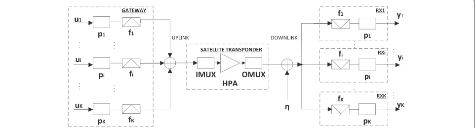
Figure 1 illustrates the system under consideration which will be further detailed in the sequel. The GW transmitsKcarriers to the satellite; where theith carrier is upconverted to a center frequencyfiafter pulse shaping withpi(·). The bandwidth of each carrier is set depend-ing on the total number of carriers and the transponder bandwidth (typically 36 MHz, but it could be as large as 500 MHz). In this study, all the carriers have the same bandwidth and are assumed to be compliant with DVB-S2 specifications.
The signals from the GW are channelized to the satel-lite HPA through a wideband input multiplexing (IMUX) filter. Typical amplitude and group delay response of such filters can be obtained from [3]. Traveling wave tube amplifiers (TWTAs) are the HPAs predominantly used onboard and are intrinsically nonlinear. Further, the TWTAs used in Ku band can be assumed to have a trans-fer characteristic largely independent of the frequency [20]. Subsequently, the output multiplexing (OMUX) filter is used to reduce the out-of-band emission before relaying the HPA output to the antenna sub-system.
From a system perspective, the DPD needs knowledge of the channel characteristics in terms of filters, ampli-fiers, etc. While this can be obtained prior to launch, the quasi-static nature of the channel, which is due to diur-nal changes and ageing, requires information about the channel at regular intervals during operation. Towards this, we assume the existence of dedicated receivers, called
reference terminals, which are capable of multicarrier pro-cessing, whose function is to provide channel estimates for calibration. Such receivers are operator managed and can have much better noise figures compared to commercial user terminals.
Signal and channel model
Letui(n)be thenth transmitted symbol in theith carrier. These symbols are pulse shaped with pi(t) yielding the complex-valued base-band signal,
si(t)= n
ui(n)pi(t−nTr). (1)
Tris the symbol duration, commonly referred to as the symbol rate. In this work, we consider pi(t) a square-root raised cosine filter with roll-off factor ρ in accor-dance with the DVB-S2 standard [3]. Each one of theK base-band signals is upconverted to a carrier frequency fi and added together. Thus, rendering the pass-band representation,
where ϕi is the phase of theith carrier used for upcon-version,j = √−1, and Re{·} denotes the real part of the complex argument.
The satellite transponder is formed by a cascade of IMUX, HPA, and the OMUX. The bandpass fil-ters (IMUX/OMUX) are modeled as finite impulse response (FIR) digital filters. The HPA is characterized by the amplitude and phase distortion curves, known as AM/AM and AM/PM curves, and are modeled by the well-known Saleh model [29]. The model is described in Equation 3, and the parameters of the model for a typical DVB-S2 application can be obtained by curve fitting to the experimental data in [3],
with z denoting the magnitude of the complex-valued base-band signal at the input of the HPA, andA, repre-senting its AM/AM and AM/PM conversion, respectively. Based on the HPA and IMUX/OMUX described above, the satellite transponder can be modeled as a nonlin-ear system with memory. The memoryless nonlinnonlin-earity causes constellation warping and ACI while the ISI is caused by the filtersper seand theircouplingwith the non-linearity. While ISI and constellation warping are present in a single carrier system [2], multicarrier systems are fur-ther affected by ACI and IMD that severely distort the received symbols [4].
The output of the transponder is received at the termi-nals perturbed by additive white Gaussian noise (AWGN). The receiver employs a filter matched to the pulse shaper pi(t). After matched filtering and sampling, the received symbols on theith carrier take the form,
yi(n)=gi bols corresponding to the ith carrier are a function of all carrier sequences throughgi(·). In general, the model gi(·) includes the time and phase delay of the channel. The phase delay contribution appears naturally in a mul-ticarrier scenario where the central frequency of a carrier does not coincide with the central frequency of the pass band of the filters involved. To keep the study focused on nonlinear effects, both time and phase delay are ideally compensated in the receiver, thus not influencing the per-formance. In the following, we develop a model of gi(·) using the MIMO Volterra series.
Volterra analysis
A time invariant nonlinear dynamic system with fading memory can be described by Volterra theory [30]. This theory has been extended to multiple input multiple out-put systems (MIMO) in [31-33]. However, it is convenient to describe the Volterra series in discrete complex base-band representation as in [6,34] since communication signals are denoted and manipulated in this domain. The continuous time MIMO Volterra [31-33] and the complex base-band formalism [34] were combined in [23], in which a complex 2×2 Volterra system was formulated. Extend-ing that results to an arbitrary number of carriers, we get:
wherei = 1,. . .,K.ui(n)andyi(n), respectively, denote the transmitted and received symbols on the ith car-rier atnth instance. Further, the signaly(ip)(n)represents the contribution of the pth nonlinear order at the ith received carrier, and{hk1,...(m1,. . .)}are the Volterra
ker-nels [30]. Note that Equation 5 only includes odd non-linear orders since those are responsible for the in-band distortion encountered at the output of the nonlinear channel [34]. For complexity reasons to be discussed below and for fostering a hardware implementation, the series in Equation 5 is truncated to a certain memory depth and nonlinear order.
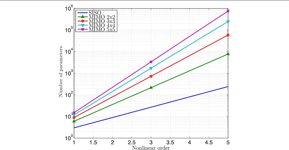
Assuming that the series (Equation 5) is truncated to Pth nonlinear order withMpbeing the memory depth for the(2p−1)th nonlinear order, the number of parameters
in Equation 5 corresponds to
P+1 2
p=1K2p−1(Mp+1)2p−1. This number exponentially increases with nonlinear order and memory depth and further motivates the truncation. Figure 2 illustrates this relationship usingMp = 2 for all nonlinear orders. The number of terms grows with the nonlinear order (P), memory depth (Mp), and the number of carriers (K). Notice that the number of parameters for the MIMO system are orders of magnitude larger than for the SISO system. Even with a modest nonlinear order of 3, a 5×5 MIMO system has 100 times more parameters than the corresponding SISO system. The large number of parameters in the latter is a well-known problem and has given rise to large research efforts in finding more
parameter-efficient models [11]. There is a certain level of redundancy in the formulation due to the permutations of the terms that can lead to identical contribution, such as,xixjx∗z = xjxix∗z, referred as symmetry [33]. The gen-eral trends are, however, the same as presented in Figure 2 even if redundancy is considered.
The Volterra model in Equation 5 describes the impair-ments in the received carrier symbols; for every nonlinear orderp. These terms can be further identified as IMD, ISI, and ACI that limit the achievable throughput. Enhancing the throughput in such situations is taken up next.
Nonlinear mitigation techniques
In this section, we describe the two designed counter-measures for multicarrier nonlinear channels: DPD and EQ. The parameter identification method applied to both techniques is presented, and, subsequently, we provide the method for complexity reduction based on a basis pursuit approach.
Multicarrier data predistortion
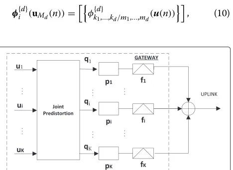
Digital predistortion (DPD), introduced at the GW, aims to mitigate the channel interference and to increase power efficiency. Joint processing of carriers allows pre-cancellation of the relevant interference generated by the IMD products. Further, processing is performed at data level (at symbol rate), prior to pulse shaping, in order to avoid signal spectral regrowth on the uplink channel
and to reduce the GW hardware requirements [21] (cf. Figure 3).
The predistorter function is designed to approximate the inverse channel, which is also nonlinear and dynamic, and hence can be described by Volterra series. As a consequence, the predistorter output for theith carrier, qi(n), 1≤i≤Kcan be described as,
qi(n)=[φi(uM(n))]Twi, (6)
where qi(n) denotes the predistorted symbols andwi is
the
P+1 2
p=1K2p−1(Mp +1)2p−1×1 vector of the predis-torter parameters which are the coefficients of the series (Equation 5). Thus, the number of parameters inwi cor-responds to the number of basis functions of the MIMO Volterra series.φi()is the vector comprising the nonlinear input combinations. In particular, we define,
u(n) = [u1(n),. . .,uK(n)]T, (7)
uM(n) =
uT(n−M),. . .uT(n+M) T. (8)
Further, the entries of the
P+1 2
p=1K2p−1(Mp+1)2p−1×1 vectorφi()are the Volterra basisφk{d}
1,...,kd/m1,...,md defined
as [34],
φ{d}
k1,...,kd/m1,...,md(u(n)) =
(d+1)/2
j=1
ukj(n−mj) . . .
d
j=(d+1)/2+1
u∗k
j(n−mj).
(9)
For each nonlinear orderd, we stack terms relative to all carrier combinations together with memory combina-tions in theK2d−1(Md+1)2d−1×1 vector
φ{d}
i (uMd(n))=
φ{d}
k1,...,kd/m1,...,md(u(n)) , (10)
Figure 3Multicarrier predistortion (DPD) architecture:Kcarriers are simultaneously processed at the GW.
with kj ∈ (1,K), mj ∈ (−Md,Md) andd denoting the nonlinear order considered. Finally, we augment vectors of different nonlinear orders obtaining,
φi(uM(n))=
φ{d}
i (uMd(n)) , (11)
with d ∈ (1,P), φi(uM(n))being a P+1
2
p=1K2p−1(2Mp + 1)2p−1×1 vector. Identification of the parameterswi is performed such that the predistorter function approx-imates the channel post-inverse. This can be achieved using the indirect learning architecture [10] where the inverse is estimated from the input and output signals. A detailed description of the parameter identification method is provided in the sequel. The number of basis functions becomes very high, as described previously; we therefore reduce their number while retaining the model performance as described below.
Multicarrier data equalization
From a system point of view, a completely different approach would be to compensate for the nonlinear inter-ference at the receiver side. Joint processing of multi-carrier signals at the user terminals can be envisaged in broadcast applications where the receiver can decode more than one carrier (professional application, for exam-ple). Such receivers are expensive with the complexity and cost compared to user receivers being dictated by the mar-ket. Another application of multicarrier equalization is on the return link. Albeit, the return link in consumer applications is usually large making equalization complex. The setup is dual of the considered scenario, where differ-ent users uplink carriers that are simultaneously amplified by the onboard HPA and processed jointly at the GW. Complexity and cost of the user receivers are also tightly limited by the market.
Multicarrier equalization for nonlinear satellite chan-nels was first introduced in [8] for a dual carrier channel. In [8], the authors designed and compared two differ-ent kinds of equalization techniques: a Volterra equalizer implementing the channel inverse function and an inter-ference canceler based on the channel function identifica-tion. Results show that the interference canceler slightly outperforms the channel inversion approach. In [4], the interference cancellation method is further extended to a turbo Volterra architecture designed for an arbitrary num-ber of carriers. In this work, we extend the dual carrier Volterra equalizer implementing the channel inverse [8] to an arbitrary number of carriers. The goal of our exercise is to reduce the receiver architecture complexity compared to [4] with minor performance degradation.
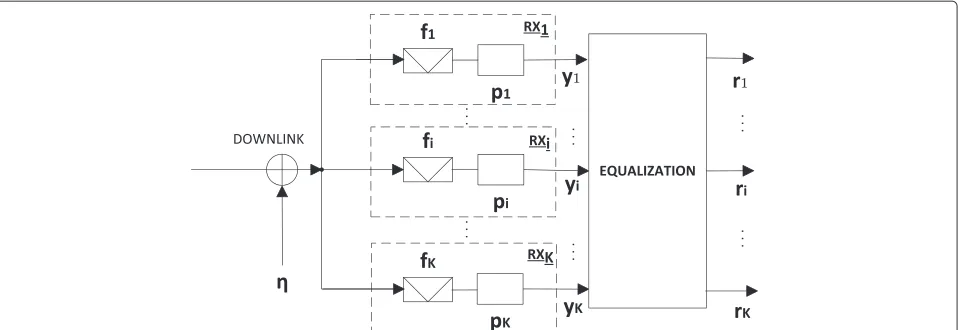
The considered equalization architecture is illustrated in Figure 4 and is described by,
Figure 4Multicarrier equalization (EQ) architecture:Kcarriers are simultaneously processed at the receiver.
where ri(n) denotes the equalized symbols and φi() is defined similarly to Equation 6 taking{yk(n)}Kk=1as inputs. Following [8], we estimate the equalizer parameterswito implement the channel post-inverse function. In the fol-lowing section, we provide the general formulation for channel post-inverse parameter identification that is valid for both DPD and EQ design.
Identification of channel inverse
From Equations 6 and 12, both the predistorter and the equalizer are described through linear model structures. Hence, the coefficients wi, denoting both the equalizer and the predistorter weights, can be estimated using linear techniques. While the aforementioned problem is formu-lated in a straightforward manner for equalizer based on Equation 12, it relates to the indirect learning architec-ture [10] for predistorter design. In the indirect learning architecture, the predistorter weights are obtained using the post-inverse (equalization) solution. In particular, we consider,
ui(n)=[φi(y(n))]Twi. (13)
Given a dedicated training sequence providingN sam-ples of transmitter and received symbols,{ui(n)}Ki=1and y(n)=[y1(n),. . .,yK(n)]T, respectively, we can stack the quantities to obtain,
si=[ui(0) . . .ui(N−1)]T, (14)
i=
⎡ ⎢ ⎣
φT i(y(0))
.. . φT
i(y(N−1)) ⎤ ⎥
⎦. (15)
From Equation 13, using Equations 14 and 15, it follows thatsi =iwi. The least squares solution forwican then be readily obtained from [35] as,
wi=
H
i i −1
H
i si, (16)
whereHdenotes the Hermitian transpose operator. The identified parameters can be equivalently used for DPD and EQ architectures. The large number of parameters in wimakes the implementation of these techniques difficult and computationally expensive in practical applications. In the following section, we describe a method for sub-stantially reducing the complexity of the model.
Complexity reduction
The parameterswi, representing the predistorter or equal-izer coefficients (cf. (16)), are basis functions of a Volterra series (of the form of Equation 5) in which the input and output have been interchanged to describe the postdis-torter function. The parameters wi are commonly esti-mated using least squares identification methods. A sys-tem modeled by the Volterra series can be represented in multiple forms. Thus, different identification meth-ods provide different system representations. Least square methods yielddensesystem representations, that is, most of the coefficients have significant weight in the model output. Hence, an implementation of the Volterra series becomes complex and its analysis cumbersome. A differ-ent approach followed by compressed sensing methods allows to reduce the number of coefficients while retain-ing the modelretain-ing properties. Such an approach is known as LASSO [27]; in the view of the principle of parsi-mony [36], such sparse model representations must be preferred. These techniques have been used successfully in SISO Volterra basis selection and polynomial models [28,37,38].
to select the significant coefficients of the system. The LASSO solves a least squares problem constraining the model to be sparse; such a constraint is usually repre-sented as a sum of the magnitude of the model parameters,
minimize
Here,Nis the total number of symbols used, the oper-ator ·2 denotes the 2 norm, and wi(n) is the nth coefficient of thewivector
wi=
Ri,n is a scalar normalizing factor required since the coefficients in the predistorter and equalizer have differ-ent scales of magnitude provided by distinct nonlinear orders.Ri,nis set as the sample variance of thenth column of the regression matrixior equivalently as the energy of thenth base function,
Ri,n= Such a normalization is recommended for basis selec-tion [40]. Despite Equaselec-tion 17 is formulated similarly to the weighted LASSO [39], it does not compute the Ridge vector required for the constraint in the weighted LASSO. In contrast to identification techniques using only the error square as a loss function, the solution of Equation 17 produces sparse solutions forcing some of the coefficients inwi to reduce to zero and hence providing an efficient basis representation for the channel inverse. Note that the weight of each basis function is given by the correspond-ing coefficient inwi, and the estimatedwiis sparse. Hence, basis functions which corresponding coefficient is zero can be eliminated without sacrificing performance. The reduction in complexity from the use of this technique is shown in the next section.
Simulations Figures of merit
The total degradation (TD) is used to evaluate the perfor-mance in coded satellite links. TD accounts for the non-linear distortion while penalizing the loss in HPA power
efficiency (measured as output power back-off (OBO)) [41],
i are the average symbol energy to noise ratios required to achieve a target bit error rate (BER) in the nonlinear channel and the ideal linear chan-nel (AWGN), respectively, for theith carrier. While Es
No is a
single carrier metric, the OBO depends on the combined signal and not on individual carriers (aggregate OBO). In all our simulations, we consider a target BER of 10−5. In contrast to equalization, the DPD will cause a change in the operating OBO of the satellite transponder due to the change in the signal statistics exciting the HPA. The OBO change, due to the use of DPD, is then included in the TD.
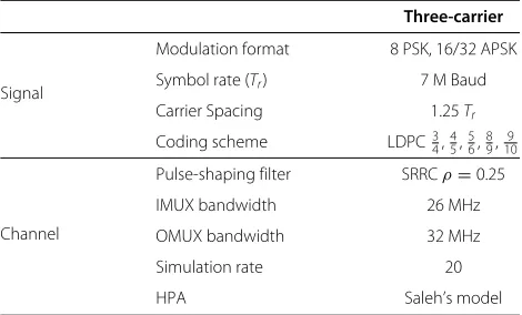
Simulation settings
The satellite transponder was simulated as the cascade of three systems: an IMUX filter, a TWTA, and an OMUX filter. The IMUX and OMUX filters were modeled by FIR structures using 51 and 41 taps, respectively, that operate at the simulation rate. The TWTA was modeled by the static nonlinear Saleh model in Equation 3 withα0 = 2,
α1 = 1,β0 = π6, andβ1 = 1. Table 1 summarizes the settings used in the simulations.
The simulation rate referred in Table 1 indicates the amount of upsampling used in the carrier signals. The upsampling is required to accurately represent the non-linear effects. These effects cause the signal bandwidth to expand and is commonly referred as spectral regrowth. The LDPC coding scheme [42] in Table 1 is representative of the state of art in satellite communications [3].
Basis selection results
The system depicted in Figure 1 was simulated using Matlab, with the settings in Table 1 exploiting the built-in libraries for modulation and codbuilt-ing that are compliant
Table 1 Simulation settings
Three-carrier
Signal
Modulation format 8 PSK, 16/32 APSK
Symbol rate (Tr) 7 M Baud
Carrier Spacing 1.25Tr
Coding scheme LDPC3
4,45,56,89,109
Channel
Pulse-shaping filter SRRCρ=0.25
IMUX bandwidth 26 MHz
OMUX bandwidth 32 MHz
Simulation rate 20
with DVB-S2 [3]. The problem in Equation 17 was solved using convex solvers [43,44].
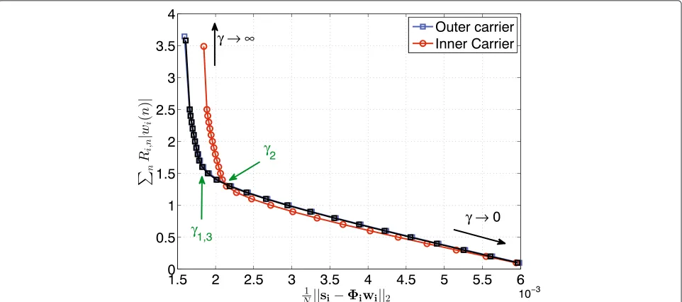
The constraints γi in Equation 17 must be adjusted properly to produce sparse/relevant basis functions. This can be addressed by plotting the Pareto optimal boundary for the problem, as depicted in Figure 5 ([45], Chapter 6). It is suggested to chooseγiat the knee point of the curve; this point provides a trade-off between number of basis functions and the goodness of fit of the model.
Note that in Figure 5, there is a region to the left in the figure where the model error (on the horizontal axis) is insensitive to variations ofnRi,n|wi(n)|(on the vertical axis). SincenRi,n|wi(n)|is a metric for the model spar-sity, by selectingγias suggested, it is possible to promote the model sparsity without compromising for the model error.
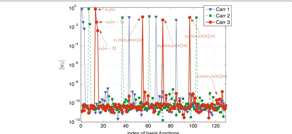
We test the Volterra model of Equation 5 for aK = 3 carrier case with the LASSO algorithm to distinguish the relevant bases for the system inverse. The simulated sys-tem is described in Figure 1 with the parameters indicated in Table 1, using 16 APSK symbols in every carrier, the transponder aggregate OBO was set to 2 dB, and the num-ber of symbols used in the basis selection corresponds to a frame in DVB-S2 [3], that is, 64,800 symbols. Figure 6 shows the magnitude of the MIMO Volterra parame-ters rendered by the LASSO solver. The predistorparame-ters are shown in colors for each carrier. Figure 6 indicates some basis functions corresponding to the predistorter of car-rier 3. The LASSO technique in Equation 17 does not produce coefficients with values equal to zero; instead very small values are rendered [46], as noted in Figure 6. Hence, we retained the basis functions with coefficientwi
larger than 10−4 in the model, and the rest were elimi-nated. Noted that from Figure 6, the amplitude variations of the vectorwiis of several orders of magnitude. Thus, altering the threshold level of 10−4, used for discriminat-ing the basis functions, did not change the basis selection results.
The Volterra basis model for the channel inverse was truncated to nonlinear order 5 and memory depthsM1= 5,M2 = 3, and M3 = 1 (5 for the linear, 3 and 1 for the third and fifth nonlinear orders, respectively). This original set of bases is redundant when considering the compensation of distortion channel effects, as can be seen in the left part of Figure 5. The ‘knee’ shape in Figure 5 indicates possible parsimonious system representation for which no degradation of the model error is observed. The total number of tested basis functions is 1,458 when con-sidering symmetric representation of Equation 5, from which only 17 basis functions are finally selected and reported in Table 2. Thus, 17 basis functions are used in the mitigation technique, which is formed as a lin-ear combination of the basis indicated in Table 2. It is worthwhile noticing in the equally spaced carrier scenario, that the third-order nonlinear termsxixjx∗kinterfere to the
(i+j−k)th carrier. This is found out during the basis selec-tion process as noted by the columns of Table 2. This 17 basis functions could be compared to the result for a mul-ticarrier equalizer in [4], where at least 30 basis functions were selected by using a different approach that resorts to enumerating the contribution at certain frequencies.
The basis selection test was repeated for different modulation formats, code rates, and operating aggregate OBOs of the HPA; despite the varied settings, the basis
Figure 6Magnitude of the parameters in the MIMO Volterra series when using the proposed LASSO solver.Reported 125 of the 1458 total parameters.
selection gives similar results to those reported in Table 2. These tests were however repeated under the following conditions:
• The carriers have the same frequency locations. • The relative power between carrier signals is kept
constant.
• The carriers have the same bandwidth (symbol rate
Tris fixed).
• The IBO is varied only in the region where significant amount of nonlinear distortion is produced.
Obtaining the same basis representation, despite the varied settings, suggests that a parsimonious system rep-resentation can be found at data domain (symbol level) which is the cause of the observed behavior. From Table 2, larger memory is required for the outer carriers than the inner (central) carrier, as they are affected more by
Table 2 Selected basis functions for the system inverse in a three-carrier satellite link
Carrier 1 Carrier 2 Carrier 3
x1(n) x2(n) x3(n)
x1(n−1) x2(n−1) x3(n−1)
x1(n−2) - x3(n−2)
x2(n)x2(n)x3∗(n) x1(n)x2(n)x∗1(n) x1(n)x3(n)x∗1(n)
x1(n)x3(n)x3∗(n) x1(n)x3(n)x∗2(n) x2(n)x2(n)x∗1(n)
x1(n)x2(n)x2∗(n) x2(n)x3(n)x∗3(n) x2(n)x3(n)x∗2(n)
The symbol * denotes the complex conjugate operator.
the IMUX and OMUX filters. Secondly, no memory is required for the third nonlinear order terms, and finally, that all fifth-order terms were ruled out from the selected basis functions.
The basis selection process can be made using other models instead of the MIMO Volterra; for instance, mem-ory polynomials [5] or phase-aligned models [47]. How-ever, the MIMO Volterra model subsumes [5] and [47]; in consequence, the results from the basis selection are not affected by this initial model choice. Although the basis selection complexity is high, the overall complex-ity of the mitigation technique is dominated by the feed forward model propagation rather than the basis selec-tion process [48]. This is due to the slow channel changes (‘diurnal’ as commonly stated in satellite applications); thereby enabling to perform the basis selection process offline.
Link performance
0 1 2 3 4 5 6 7 0
0.05 0.1 0.15 0.2 0.25
Aggregate OBO (dB)
OBO Loss (dB)
8 PSK 16 APSK 32 APSK
Figure 7Average loss in OBO at the satellite transponder due to the use of the proposed multicarrier data DPD.
without DPD for a fixed IBO. Note that for lower values of OBO, the effect is larger as higher levels of distor-tions arise in the channel. The OBO loss depends on the modulation format as 16/32 APSK are sensitive to non-linear effects. Finally, note that for large values of OBO,
the losses decrease as the channel behaves more linearly and the DPD effect becomes minor. From a power effi-ciency perspective, the loss in OBO is undesirable and it negatively affects the link performance. However, the DPD algorithm proposed in this paper causes OBO losses of a few tenths of a dB (cf. Figure 7). Further, the loss in OBO is more than compensated by the gains obtained in Es/No, leading to enhanced TD as will be shown below.
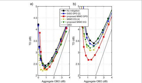
Figure 8 shows the TD of the three-carrier satellite link as a function of OBO in the HPA; for 16 APSK using a
3
4code rate, the outer and inner carriers are presented in Figure 8a and Figure 8b, respectively. In this comparison, solely data mitigation techniques are presented. The TD of only one outer carrier is shown due to symmetry. In Figure 8, the benefit of applying nonlinear mitigation tech-niques can be observed. Figure 8 includes single carrier data DPD for comparison [2]. Since single carrier predis-tortion does not include intermodulation products, it is ineffective at combating nonlinear distortions appearing in the multicarrier scenario; consequently, it has poorer performance compared to the proposed multicarrier data predistortion (cf. Figure 8). The proposed data equalizer is compared with the multicarrier interference canceler of [4]. It can be observed from Figure 8 that the proposed
0 1 2 3 4
2 2.5 3 3.5 4 4.5 5
Aggregate OBO (dB)
TD (dB)
0 1 2 3 4
2 2.5 3 3.5 4 4.5 5
Aggregate OBO (dB)
TD (dB)
No mitigation SISO DPD [2] proposed MIMO DPD MIMO EQ [4] proposed MIMO EQ OBO
a)
b)
EQ scheme has some losses compared to the reference receiver technique of [4]. In fact, the multiple carrier turbo Volterra equalizer [4] relies on the powerful, but highly complex, iterative interference cancellation and decoding paradigm. On the other hand, our proposed low com-plexity equalization does not include any data decoding nor interference cancellation. Further, the proposed EQ has the same complexity of the proposed DPD technique, which is dual for the gateway. The complexity of the DPD is further discussed in the following sections. As seen Figure 8, the TD performance depends on the carrier location, as the inner carrier exhibits significantly more degradation than the outer ones. While the benefit of applying multicarrier over single carrier mitigation tech-niques is evident at the inner carrier, the performance gain is lower in the outer carriers where memory effects (ISI) dominate over ACI.
The investigated multicarrier mitigation techniques show different performance in Figure 8. The differences are due to the effects of the receiver noise, both in the identification stage as well as during operation. While the DPD uses a dedicated receiver that can be designed to have low noise, the equalization has to operateon-the-fly at the receiver with higher levels of noise as in standard operation mode. Note that the equalizer has to operate on received signals which are corrupted by AWGN. Since the equalization operation is nonlinear in the received sym-bols, the subsequent elements of the chain are affected by a nonlinear function of the front-end noise. This aspect is missing in the DPD and hence it provides further perfor-mance enhancement (cf. Figure 8).
Figure 9 compares the TD performance when using three different DPD schemes: i) the multicarrier data memory polynomial DPD [5]; ii) the proposed multicar-rier data DPD in Table 2; iii) single carmulticar-rier waveform signal DPD [19]. The outer and inner carriers are presented in Figure 9a and Figure 9b, respectively. The multicarrier data level memory polynomial [5] has 216 polynomial basis and shows similar TD performance as the pro-posed data level predistorter which uses only 17 basis functions. Hence, for the multicarrier data DPD schemes, there is a large complexity reduction of the predistorter with no degradation in TD performance. Notice that the single carrier DPD [19] is not a multicarrier technique and presents a larger complexity when compared to data schemes.
Table 3 compares the computational complexity of the different DPD schemes. The complexity is measured with number of floating point operations per second (FLOPS). That is, combining the predistorter computation (number of operations) with its digital processing rate to produce a metric of the computational resources used per sec-ond. The predistorter computation refers to the resources required to propagate one symbol from the input to the
0 2 4
Figure 9TD versus aggregate OBO for three different DPD schemes operating in a three-carrier satellite link using 16 APSK 3
4in every carrier.(a)Outer carrier.(b)Inner carrier.
Table 3 Comparison of DPD schemes
MIMO (multicarrier) SISO (single carrier)
Scheme Proposed DPD - Table 2 Memory polynomial [5] Signal DPD [19]
# carriers 3 3 1
# basis 17 216 52
Digital processing Tr Tr 7×3(1+ρ)Tr
rate (Msamples/s) 7 7 183.75
FLOPS (106) 1,750 19,280 163,400
hardware architecture and a frequency mask to fulfill the stringent control of the out-of-band emissions from the gateway. Moreover, signal DPD requires more than 90 times the amount of FLOPS compared to the proposed solution. The increase in the number of FLOPS from the proposed DPD scheme to the memory polynomial [5] is due to the increase in the number of operations (from 17 to 216 basis functions). However, the increase in num-ber of FLOPS between the multicarrier and single carrier DPD schemes is mainly due to increase of the digital pro-cessing rate. In particular, the large amount of FLOPS in signal DPD [19] is due to its high digital processing rate, as it operates 173.75/7 ≈ 26 times faster than the other DPD schemes studied. This increased digital processing rate is required to faithfully represent the nonlinear oper-ators which enlarge the available input bandwidth, thereby requiring a larger digital processing rate.
Extensive simulations were performed for several mod-ulation formats and code rates in order to determine the performance of the mitigation techniques. In all presented results, the TD was obtained by sweeping the signal-to-noise ratio (Es/No) of the received symbols until the target BER of 10−5was achieved. The TD showed trends sim-ilar to Figure 8. In general, the level of TD is affected by the modulation format and the code rate. First, the TD increases as the number of constellation symbols increases; this can be explained by the higher sensitivity of the higher modulation formats resulting in higher levels of TD. Secondly, TD decreases as the ratio of redundancy and information increases in the code rate; this is expected as the error correcting property of the decoder improves with redundancy [42].
In a multicarrier scenario, the optimal (minimum) TD may appear at different OBO levels for different carri-ers. This effect could complicate the task of choosing the operating point of the HPA, leading to compromises between different carriers. For instance, in Figure 8 for the case with no mitigation techniques, the optimal TD of the inner and outer carrier occurs at around 1.8 and 1 dB aggregate OBO, respectively. The use of multicarrier mitigation techniques also helps reducing the difference in OBO between the optimal TD of different carriers and
consequently the need for compromising between them, as depicted in Figures 8 and 9.
Sensitivity results
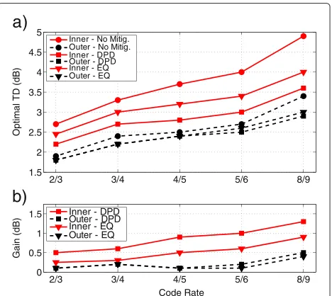
Total degradation shows a convex behavior with respect to the OBO (cf. Figure 8 ). TD is sensitive to the transmis-sion scheme, especially to the modulation and code rate. In Figure 10, we show the trend of the optimal TD per car-rier with respect to the code rate for a fixed modulation of 16 APSK.
As expected, the degradation increases with the code rate, while at the same time, relative gains of the applied DPD and equalization techniques increase as well. This is intuitively justifiable noticing that when a strong code is applied, the channel is typically in a noise-limited regime and the nonlinear mitigation techniques have a minor effect on performance. On the other hand, when a weak
8/9 5/6
4/5 3/4
2/3 1.5
2 2.5 3 3.5 4 4.5 5
Optimal TD (dB)
8/9 5/6
4/5 3/4
2/3 0 0.5 1 1.5
Code Rate
Gain (dB)
Inner - No Mitig. Outer - No Mitig. Inner - DPD Outer - DPD Inner - EQ Outer - EQ
Inner - DPD Outer - DPD Inner - EQ Outer - EQ
a)
b)
code rate is applied, the channel is in an interference-limited regime and the benefits of mitigation techniques become more relevant.
Figure 11 shows the optimal TD in the inner carrier (worst-case performance) of the three-carrier system as a function of the spectral efficiency. Simulations of different modulation formats and code rates were performed. For every modulation format considered, the minimum and maximum code rate settings of [3] have been included in this simulation. The spectral efficiency is proportional to Rlog2(S), withRbeing the code rate andSthe number of constellation symbols in the modulation format.
In Figure 11, we notice that for a given TD, the channel spectral efficiency can be significantly increased by apply-ing mitigation techniques and changapply-ing the modulation format.
Conclusions
This paper studied the use of nonlinear mitigation tech-niques to the situation where multiple carriers were amplified by a single HPA in a satellite transponder. The mitigation techniques, predistortion (DPD), and equal-ization (EQ), are described in the framework of MIMO Volterra series. However, the large number of coefficients required in the mitigation techniques limits their practi-cal applicability. In this paper, a basis pursuit approach is employed using the LASSO algorithm to reduce the com-plexity of the mitigation technique yielding models with fewer number of coefficients that keep limited model-ing error. In general, the model complexity of mitigatmodel-ing techniques grows with increasing number of carriers and hence the need for complexity reduction is exacerbated in the DPD/EQ models. Although the LASSO method
Figure 11Dependence of the TD on spectral efficiency: three-carrier simulation, inner carrier result reported.
described in this paper has been applied in a three-carrier scenario, it can still be used for larger number of carriers. The LASSO approach would also be of benefit in terres-trial applications where signal DPD is used for concurrent multiband HPAs.
The proposed DPD mitigation scheme reduces the com-plexity (measured as the number of FLOPS) of multicar-rier memory polynomial models by a factor of 10 while achieving nearly the same TD performance. On the other hand, single carrier signal DPD achieves better TD per-formance than the proposed mitigation at an expense of 90 times more FLOPS. Extensive simulations showed that the use of the proposed mitigation techniques is favorable to the overall link performance. Moreover, for a specific TD, the use of these techniques allow to operate the HPA at lower OBO which improves the power efficiency.
It was found that DPD gave better performance than equalization in terms of TD. The explanation of this dif-ference is the level of noise in the received signals. While DPD is estimated using the received data from a reference receiver, which is designed to be low noise, EQ is evaluated at higher noise levels, from standard receivers. Further, the proposed equalizer is obtained as the channel inverse which prevents the received noise power being used into its estimation procedure and causes a bias in the esti-mates [49]. Moreover, DPD operates on nearly noiseless data from the transmitter, while the EQ operates on the received noisy data. This implies that in the EQ, the noise at the receiver propagates through a nonlinear compen-sation scheme, which is missing in the DPD and further explains the different gains in performance.
Abbreviations
ACI: adjacent channel interference; APSK: amplitude and phase shift keying; AWGN: additive white Gaussian noise; BER: bit error rate; DPD: digital predistortion; DTH: directtohome; DVBS2: Digital Video Broadcasting -Satellite - Second Generation; EQ: equalization; GW: gateway; HPA: high-power amplifier; IBO: input back-off; IMD: inter-modulation products; IMUX: input multiplexing; ISI: intersymbol interference; LASSO: least absolute shrinkage and selection operator; LDPC: low-density parity-check; MIMO: multiple input multiple output; OBO: output back-off; OMUX: output multiplexing; SISO: single input single output; SRRC: square root raised cosine; TD: total degradation; TWTA: traveling wave tube amplifier.
Competing interests
The authors declare that they have no competing interests. Author details
1Department of Electronics, Mathematics and Natural Sciences, University of Gävle, Kungsbäcksvägen 47, 801-76 Gävle, Sweden.2Department of Signal Processing, The Royal Institute of Technology KTH, Osquldas väg. 10, 100-44 Stockholm, Sweden.3Interdisciplinary Centre for Security, Reliability and Trust (SnT), University of Luxembourg, 4, rue Alphonse Weicker, L-2721, Luxembourg. Received: 16 June 2014 Accepted: 4 March 2015
References
2. E Casini, R De Gaudenzi, A Ginesi, DVB- S2 modem algorithms design and performance over typical satellite channels. Int. J. Satell. Commun. Netw. 22(3), 281–318 (2004)
3. ETSI Standard, Digital Video Broadcasting (DVB), Second generation framing structure, channel coding and modulation systems for broadcasting, interactive services, news gathering and other broadband satellite applications (DVB-S2). European Telecommunications Standards Institute (ETSI) EN 302 307 V1.1.2 (2006-06)
4. BF Beidas, Intermodulation distortion in multicarrier satellite systems: analysis and turbo Volterra equalization. IEEE Trans. Commun.59(6), 1580–1590 (2011)
5. R Piazza, MR Bhavani Shankar, E Zenteno, D Rönnow, J Grotz, F Zimmer, M Grasslin, Heckmann F, S Cioni, inProc. 30th AIAA Int. Comm. Satellite, Systems Conf. (ICSSC). Multicarrier digital pre-distortion/equalization techniques for non-linear satellite channels (Ottawa, Canada, 2012) 6. S Benedetto, E Biglieri, Nonlinear equalization of digital satellite channels.
IEEE J. Sel. Areas Commun.1, 57–62 (1983)
7. L Ding, GT Zhou, DR Morgan, Z Ma, JS Kenney, J Kim, Giardina C R, A robust digital baseband predistorter constructed using memory polynomials. IEEE Trans. Commun.52(1), 159–165 (2004) 8. BF Beidas, R Seshadri, Analysis and compensation for nonlinear
interference of two high-order modulation carriers over satellite link. IEEE Trans. Commun.58(6), 1824–1833 (2010)
9. M Allegue-Martinez, N Kelly, A Zhu, Digital linear pre-compensation technique to enhance predistortion performance in multicarrier DVB-S2 satellite communication systems. Electron. Lett.50(13), 957–959 (2014) 10. C Eun, EJ Powers, A new Volterra predistorter based on the indirect
learning architecture. IEEE Trans. Signal Process.45(1), 223–227 (1997) 11. M Isaksson, D Wisell, D Rönnow, A comparative analysis of behavioral
models for RF power amplifiers. IEEE Trans. Microw. Theory Tech.54(1), 348–359 (2006)
12. F Langlet, D Roviras, A Mallet, F Castanie, inProc. Int. Joint Conf. Neural, Networks, (IJCNN). Mixed analog/digital implementation of MLP NN for predistortion, vol. 3 (Honolulu, HI, 2002), pp. 2825–2830
13. S Bouchired, M Ibnkahla, D Roviras, F Castanie, inIEEE Int. Conf. Acoustics, Speech, and Signal, Processing. Equalization of satellite UMTS channels using neural network devices, vol. 5 (Phoenix, AZ, 1999), pp. 2563–2566 14. N Naskas, Y Papananos, Neural-network-based adaptive baseband
predistortion method for RF, power amplifiers. IEEE Trans. Circuits Syst. II Exp. Briefs.51(11), 619–623 (2004)
15. M Isaksson, D Wisell, D Rönnow, Wide-band dynamic modeling of power amplifiers using radial-basis function neural networks. IEEE Trans. Microw. Theory Tech.53(11), 3422–3428 (2005)
16. R Zayani, R Bouallegue, D Roviras, inIEEE 21st Int. Symp. Personal, Indoor and Mobile Radio Communications (PIMRC). Crossover neural network predistorter for the compensation of crosstalk and nonlinearity in MIMO OFDM systems (Istanbul, Turkey, 2010), pp. 966–970
17. R Piazza, B Shankar, B Ottersten, inIEEE Int. Conf. Communications (ICC). Multicarrier LUT-based data predistortion for non-linear satellite channels (Sydney, NSW, 2014), pp. 4319–4324. doi:10.1109/ICC.2014.6883999 18. T Deleu, M Dervin, F Horlin, inIEEE Int. Conf. Communications (ICC). Low
complexity block pre-distortion of a multi-carrier non-linear satellite channel (Sydney, NSW, 2014), pp. 4325–4330.
doi:10.1109/ICC.2014.6884000
19. N Kelly, A Zhu, TJ Brazil, inProc. 31th AIAA Int. Comm. Satellite, Systems Conf. (ICSSC). Digital predistortion feasibility studies for multicarrier satellite communication systems (Florence, Italy, 2013)
20. GE Corazza,Digital Satellite Communications, Chapter 8. (Springer, New York, USA, 2007)
21. J Kim, Roblin P, D Chaillot, Z Xie, A generalized architecture for the frequency-selective digital predistortion linearization technique. IEEE Trans. Microw. Theory Tech.61(1), 596–605 (2013)
22. SA Bassam, M Helaoui, FM Ghannouchi, Crossover digital predistorter for the compensation of crosstalk and nonlinearity in MIMO transmitters. IEEE Trans. Microw. Theory Tech.57(5), 1119–1128 (2009)
23. S Amin, PN Landin, P Händel, D Rönnow, Behavioral modeling and linearization of crosstalk and memory effects in RF MIMO transmitters. IEEE Trans. Microw. Theory Tech.62(4), 810–823 (2014)
24. SA Bassam, W Chen, M Helaoui, FM Ghannouchi, Z Feng, Linearization of concurrent dual-band power amplifier based on 2D-DPD technique. IEEE Microw. Wireless Compon. Lett.21(12), 685–687 (2011)
25. J Harmon, SG Wilson, inMilitary Comm. Conf., (MILCOM). Remote satellite amplifier predistortion using the indirect learning architecture (San Jose, CA, 2010), pp. 335–340. doi:10.1109/MILCOM.2010.5680352
26. G Colavolpe, Piemontese A, inProc. IEEE Global Telecommun. Conf.; Houston, USA. Novel SISO detection algorithms for nonlinear satellite channels (IEEE, Piscataway, 2011)
27. R Tibshirani, Regression shrinkage and selection via the LASSO. J. R. Statist. Soc. B.58(1), 267–288 (1994)
28. V Kekatos, GB Giannakis, Sparse Volterra and polynomial regression models: recoverability and estimation. IEEE Trans. Signal Process.59(12), 5907–5920 (2011)
29. AAM Saleh, Frequency-independent and frequency-dependent nonlinear models of TWT amplifiers. IEEE Trans. Commun.29(11), 1715–1720 (1981) 30. M Schetzen,The Volterra and Wiener Theories of Nonlinear Systems. (Wiley &
Sons, New York, 1980)
31. LM Li, SA Billings, Generalized frequency response functions and output response synthesis for mimo non-linear systems. Int. J. Control.79(1), 53–62 (2006)
32. ZK Peng, ZQ Lang, SA Billings, Non-linear output frequency response functions for multi-input non-linear Volterra systems. Int. J. Control.80(6), 843–855 (2007)
33. AK Swain, SA Billings, Generalized frequency response function matrix for MIMO non-linear systems. Int. J. Control.74(8), 829–844 (2001) 34. DR Hummels, R Gitchell, Equivalent low-pass representations for
bandpass Volterra systems. IEEE Trans. Commun.28(1), 140–142 (1980) 35. SM Kay,Fundamentals of Statistical Signal Processing: Estimation Theory.
(Prentice-Hall, Inc, Upper Saddle, River, NJ, USA, 1993)
36. P Stoica, B Friedlaner, Söderström T, On the parsimony principle. Int. J. Control.36(3), 409–418 (1982)
37. K Shi, P Shi, Adaptive sparse volterra system identification with0-norm
penalty. Signal Process.91(10), 2432–2436 (2011)
38. N Kalouptsidis, G Mileounis, B Babadi, V Tarokh, Adaptive algorithms for sparse system identification. Signal Process.91(8), 1910–1919 (2011) 39. H Zou, The adaptive LASSO and its oracle properties. J. Am. Statist. Assoc.
101(476), 1418–1429 (2006)
40. J Huang, P Breheny, S Ma, A selective review of group selection in high-dimensional models. Statist. Sci.27(4), 481–499 (2012) 41. M Aloisio, E Casini, A Ginesi, Evolution of space traveling-wave tube
amplifier requirements and specifications for modern communication satellites. IEEE Trans. Electron Devices.54(7), 1587–1596 (2007) 42. RG Gallager. Low density parity-check codes (PhD thesis, MIT Press
Cambridge MA, 1963)
43. M Grant, S Boyd,Graph implementations for nonsmooth convex programs. Recent Advances in Learning and Control. Lecture Notes in Control and Information Sciences. (V Blondel, S Boyd, H Kimura, eds.) (Springer-Verlag Limited, New York, 2008)
44. M Grant, S Boyd, CVX: Matlab Software for Disciplined Convex
Programming, version 2.1. http://cvxr.com/cvx, Accessed 25/March/2015 45. DG Luenberger,Microeconomic Theory. (McGraw-Hill, New York, 1995) 46. A Wächter, LT Biegler, On the implementation of an interior-point filter
line-search algorithm for large-scale nonlinear programming. Math. Program.106(1), 25–57 (2006)
47. M Younes, Kwan A, M Rawat, FM Ghannouchi, Linearization of concurrent tri-band transmitters using 3-D phase-aligned pruned Volterra model. Microw. Theory Tech. IEEE Trans.61(12), 4569–4578 (2013)
48. A Tehrani, H Cao, S Afsardoost, T Eriksson, M Isaksson, C Fager, A comparative analysis of the complexity/accuracy tradeoff in power amplifier behavioral models. IEEE Trans. Microw. Theory Tech.58(6), 1510–1520 (2010)