CSEIT1846114 | Published – 08 May 2018 | May-June 2018 [ (4 ) 6 : 610-616 ]
National conference on Engineering Innovations and Solutions (NCEIS – 2018)
International Journal of Scientific Research in Computer Science, Engineering and Information Technology
© 2018 IJSRCSEIT | Volume 4 | Issue 6 | ISSN: 2456-3307
610
Efficient Underwater Communication using Rechargeable
Mobile Sink Node
Sushma V
Assistant Professor, Department of ISE, GSSSIETW, Mysuru, Karnataka, India
ABSTRACT
Underwater Wireless Sensor Networks (UWSNs) is a collection of organized and distributed wireless communication networks that comprises of enormous number of sensor nodes in underwater. The emerging wireless charging technology is a promising alternative to address the power constraint problem in sensor networks. Comparing to existing approaches, this technology can replenish energy in a more controllable manner and does not require accurate location of or physical alignment to sensor nodes. However, little work has been reported on designing and implementing a wireless charging system for sensor networks. In this paper, we design such a system, build a proof-of-concept prototype, conduct experiments on the prototype to evaluate its feasibility and performance in small-scale networks, and conduct extensive simulations to study its performance in large-scale networks. The proposed system can utilize the wireless charging technology effectively to prolong the network lifetime through delivering energy by a robot to where it is needed.
Keywords. Underwater Wireless Sensor Networks, Charging System, Energy, Performance, Mobile Sink
I.
INTRODUCTIONUnderwater Wireless Sensor Networks (UWSNs) is a collection of organized and distributed wireless
communication networks that comprises of
enormous number of sensor nodes in underwater. Although covering more than 70% of the Earth surface the oceans are not well known, due to its dimensions, difficulties of oceanographic data acquisition and the high costs of maritime operations. Nevertheless, there is an increasing interest on oceanographic data, due to its influence on the weather, fishing, navigation, biology, ecology and
support for petroleum resources offshore
exploration[1]. The use of such sensors is increasing rapidly in many fields. These Underwater Sensor Networks are used for water quality surveillance, gas/oil spills monitoring, oceanographic data
gathering, offshore survey or examination,
submarine identification and diagnosis, catastrophe
interception, pollution monitoring, military
surveillance etc [2][3][4].These underwater sensors resemble the terrestrial sensors. However, the UWSNs do not use radio signal or electromagnetic signals. Instead, they make use of acoustic signals [5]. Due to the usage of acoustic communication, underwater sensors face large propagation delay, refraction, multipath interference, and high error rate and low communication bandwidth. There are many differentiations between underwater sensor networks and open ground environment.
communication signals. There are many restrictions to the sensor nodes in underwater environment. Some of them are salinity, humidity, temperature,
mobility of nodes, changing underwater
environment. Due to the high attenuation which are found or sensed in electromagnetic signals in water environment, it is not at all suitable for underwater communication [6].
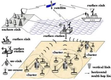
Figure 1. A View Of UWSN Environment
II.
CHALLENGES1. Propagation and Attenuation
Underwater medium mainly uses acoustic signals for communication purpose. These signal have lower speed compared to radio waves. Some of the characteristics of communication in water medium such as scattering, absorption, refraction creates obstacle for signal propagation in underwater medium. Attenuation can be defined as the decrease in the intensity of the signal during propagation. Attenuation is high in underwater medium. [6]
2. Localization and security issues with respect to the nodes and their communication in the network
3. Synchronization of the clock time of sensor nodes 4. Management of energy inorder to secure lifetime
of the network[7]
5. Available communication link/bandwidth is
limited due to the lack of fair channel sharing mechanisms.
III.
APPLICATIONS OF UNDERWATER SENSOR NETWORK Seismic Tracking – One of the advantageous application of underwater sensor are
seismic-tracking/surveillance for withdrawal of
oil/lubricant from subaqueous/marine areas [7]. “4 – D seismic” are widely utilized in determining the performance. It is also useful in the process of motivation intervention.
Underwater cyborg - This supports groups of underwater autonomous cyborg which are also known as robots that can eventually sense, collect and transmit data such as chemical leakage or biological phantasm like phytoplankton flocking and also equipment managing [10].
IV.
RELATED WORKA. Location based Clustering Algorithm for Data Gathering (LCAD)
The transmission of data between sender and receiver sensor nodes depends upon the distance between them which in turn relies on the energy consumption. Due to the large number of data packets, it can lead to draining off the sensor node's energy. In Cluster based architecture for a three dimensional underwater sensor network where the sensor nodes are deployed at fixed relative depth from each other. All the sensor nodes are organized at their respective positions with the help of respective cluster heads, where the cluster heads are interlinked with each other by horizontal acoustic links, with a length restricted to a maximum of 500m for an effective communication proved in [8]. For a range of more than 500m, the use of autonomous underwater vehicle is practiced.
Phases of Communication.
a) Initial Setting Up Phase – Selection of cluster head among the ordinary sensor nodes takes place. This process is supported by an efficient and reliable algorithm.
sensed data are forwarded to the respective cluster head. Once the data has been received by the cluster head, it aggregated all the data to form a data packet with less number of chunks in order to ensure the highest data packet delivery ratio c) Transmission Phase – Once the data has been
aggregated, it is further transmitted / collected by
the autonomous vehicles. Autonomous
underwater vehicles collect data packets from the cluster heads rather than every single sensor node in the network. These vehicles transfer the data to the sink/destination.
Cluster heads possess more memory and energy as compared to the member nodes as more memory and energy is consumed by the cluster heads as compared to the member nodes and retrospect, it makes the sensor network not only more reliable, but also balance the load in the network. It has formed a grid structure just like a cellular network, where the cluster head is located at the center, which helps it in communicating efficiently with the respective member nodes. Therefore, for the most optimal results, they supported a compact deployment of sensor nodes at the lower level of the structure and more dispersed at the higher level of the structure.
In accordance to the simulation results, the work has proved itself to be effective in terms of network lifetime. Though, location based clustering algorithm for data gathering has numerous advantages over environments as node mobility is the prime concern as in case of the underwater sensor network. In underwater sensor networks, the nodes can move with the ocean current and can leave the network. Therefore, it could be possible that the nodes enter the neighbor grid or leave different grids frequently resulting in communication loss.
B. Distributed Minimum-Cost Clustering Protocol (MCCP)
The nature of cluster formation in terrestrial sensor network is not feasible with respect to the underwater sensor networks[5]. Thus the protocols proposed for cluster formation in the terrestrial sensor network do not hold the same reliability and efficiency in underwater sensor network due the challenges faced in underwater environment are more complicated than terrestrial networks. Distributed Minimum-Cost Clustering Protocol (MCCP) uses a cluster based approach in order to improve energy efficiency and prolong the network life. It consists of three parameters . residual energy and relative location of cluster head and sink in this approach, every node construct its neighbor set and their respective cost is calculated. Further, the average cost is computed and the minimum cost is selected as cluster head [10].
Cluster Head (CH) broadcasts an INVITE message to all the other cluster nodes to become its cluster's member, otherwise it sends a JOIN message to the specific cluster head.
Although, MCCP is an efficient centralized algorithm for data aggregation as it eschews the formation of hot spots near the underwater sink.Also, it has the ability to rebalance the traffic by clustering the sensor nodes time to time. But it has a few drawbacks as well, such as it does not support multi-hop routing. It has the ability to re-cluster the network, but re-clustering the network can take months, due to which it could be possible that the nodes can leave and enter different clusters as the underwater sensor network is assumed to be mobile.
C. Distributed Underwater Clustering Scheme (DUCS)
a clustering scheme which supports the node mobility and energy degradation issue, and named it as distributed underwater clustering scheme (DUCS), an adaptive self-organizing protocol where the nodes organize themselves into clusters and a cluster head is selected from each cluster. The cluster head agglomerates the data sent by the respective cluster members as shown in Figurer.
Figure 2. Network using DUCS
Data transfer between the member nodes and the cluster head takes place via a single hop. After that, the cluster head performs data aggregation on the received data and forward the data to the sink via multi-hop routing with the help of remaining cluster heads, the redundancy of data is minimized and the energy is saved[5]. Cluster heads are responsible for both inter-cluster communication as well as intra-cluster communication.
Cluster heads are selected through a randomized rotation among different nodes in order to avoid draining of the battery from a particular node. DUCS works in two rounds. (i)Set-up Phase. A network is formed by dividing the network into a number of clusters and cluster heads are formed using the respective cluster formation algorithm; (ii) Network operation phase. Transfer of the packets is completed in this phase. DUCS has turned out to be an efficient clustering and aggregation scheme as simulation results have shown increased throughput and also achieves a high packet delivery ratio.
Although this scheme is efficient, but it has some serious issues like node mobility is not considered so node movements due to ocean currents can affect the structure of clusters that it reduces the network overhead. Also, the cluster head is bound to send the data to another cluster head only. In that case, ocean currents can move two cluster head nodes far away such that, while data transfer between the two cluster head, there are a few non-cluster head nodes available between them.
D. HydroCast
Uichin et al. [10] proposed a hydraulic pressure based anycast routing protocol called HydroCast in order to overcome the limitations of geographic routing.
Since geographical routing in underwater
environment is quite complex and consumes more cost, there was an urge to solve routing problems. Thus the HydroCast algorithm analyzes the pressure levels by measuring and comparing the levels at different geographical locations. It uses the measured pressure levels to find the routes for forwarding packets from source to the sink/surface buoys. It is stateless and completes its task without requiring expensive distributed localization. Hydrocast nodes are designed with a low cost pressure sensor to measure their own depth locally.
Multiple mobile sinks are also deployed on water surface, which move with water flow. With regard to discovering a positive progress area toward to the sink, this protocol exploits only the information that is estimated by measuring the pressure of water in different depths.
priority[11]. In this subset a node will forward the packet only when all nodes with higher priority progress to the destination fail to send it. This process is scheduled with the use of a back-off timer which is set up proportional to the destination’s distance. All the other sensors with lower priorities will suppress their transmissions upon receiving the transmission (data or ACK packet) of a higher priority node. By this way the possibility of collisions and redundant transmissions is minimized. In the second stage, a local maximum recovery mechanism is introduced in order to deal with the communication void. A node is considered as a local maximum node if there are no neighbours with lower pressure levels[17]. To overcome this problem it enables a void handling mechanism. According to this, each local maximum node finds and stores a recovery path to a node whose depth is lower than itself and transmits the data packet to this node.
V.
CLUSTERED BASED MOBILE SINKMobile sink schemes improves network lifetime. However, previous studies on sink mobility either assume that global information of the network is already available or the mobile sink convey the global information through repeated network wide broadcasting. Thus the gain in network lifetime can be offset by the broadcasting which incurs extra high energy consumption.
In This scheme used following steps.
1. Initially network is initialized by sending activation packet and every node in a network assumes itself as a cluster.
2. Clusters are formed by using distance and residual energy.
3. Cluster Head are chosen from the cluster with highest energy and it changes after each round. 4. CH aggregates the data send from the cluster node and send it to the sink.
5. After each round sink changed its position randomly so that energy consumption is uniform.
6. If each round CH has not sufficient energy, then re-clustering is done.
A. Cluster Head Formation
Among that multiple CH, the present CH is selected using Sleep Wake pattern. The awake CH send CHADV message contain Node Id and an Integer Count. The NCH waits for some times ADVWT for receiving all CHADV from all the potential CH. Then the NCH choose their corresponding CH which is having minimum Integer Count. If more than a CH having minimum Integer Count then it chosen the minimum Id. After that, the CH waits for CH-JOIN for a period of JOIN-WT. After CH selection the data transfer will be done within the cluster. The NCH send the data to CH and CH send it to base station. For intra cluster communication, no need for any control information. For inter communication the route is discovered using the control information [12].
a) Route Discover
The first data packet from source to destination node due to carries the route-discovering packet
energy constraints. The source check the existing route for destination, if there is not existing route then the packet will send to destination. After getting the data packet the destination send the acknowledgement along with reverse path to the source.
b) Route Maintenance
Each path from source to destination has time property called ROUTE LIFETIME. When the lifetime exceeds the threshold denotes TIMEOUT and inform that the route is invalid. Node uses the same path before threshold the lifetime is reset to “0”.
c) Route Retraction
d) Periodic Sleeping
The nodes shut down the transceiver till the next sampling or receiving will be done. [9]
Figure 3. Sink Relocation
Therefore the sink only needs to broadcast across the network to inform all sensor nodes of its current location P0 at the very beginning for just one time.
Later on, as sensor nodes keep record of the original location of the sink, they can reduce the changed angle _ after a time interval t .
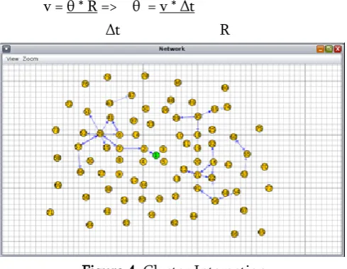
v = θ * R => θ = v * Δt Δt R
Figure 4. Cluster Interaction
e) Charging Phase
The system has three main components. a mobile charger (MC) – a mobile robot carrying a wireless power charger, a network of sensor nodes equipped with wireless power receivers, and an energy station that monitors the energy status of the network and directs the MC to charge sensor nodes.
Figure 5. Charging Phase
The system works as follows. Sensor nodes perform application tasks such as environment monitoring, generate sensory data, and periodically report the data to the sink.
In addition, they also monitor the voltage readings of their own batteries, estimate energy consumption rates, based on which derive their own lifetime, and then report the information to the sink periodically. When the energy information is forwarded to the sink, it is aggregated en-route to save communication overhead. Particularly, only the energy information of the k shortest-lifetime nodes is forwarded while the information of other nodes is dropped, where k is a system parameter. Upon receiving the energy information, the sink forwards it to the energy station, which runs a charging algorithm to process the information and plan the charging activities, and then sends a command message to the MC. The command includes the charging plan that the MC should execute. Once receiving the command, the MC starts charging a selected set of sensor nodes sequentially according to the instruction. When the MC receives a new command, it adjusts its charging activities accordingly.
VI.
CONCLUSIONclustering algorithm adopting a mobile sink and reducing the energy consumption of the nodes does not necessarily reduce the energy dissipation of wireless sensor network. Instead, a careful selection of the nodes and of mobility radius of the sink is required in order to achieve higher energy efficiency compare to a static sink. Moreover, conclude that in comparison to a static sink placed at the center of the wireless sensor networks, a mobile sink can reduce energy significantly, Irrespective of the mobility radius of the sink. We propose a wireless charging system for sensor networks that provides an efficient way of communication in underwater sensor networks.
VII.
REFERENCES[1] Z. Wei, G. Yang, and Y. Cong, “Security of underwater sensor networks”, Chinese Journal of Comuters, vol.35, no.8, pp. 1594-1606, 2012. [2] Y. Chen, X.M. Xu, and L. Zhang, “Design of RC – LDPC codes and its application for shallow water acoustics communications”, Journal of Convergence Information Technology, vol.7, no.12, pp.177-185, 2012. IARJSET ISSN (Online) 2393-8021 ISSN (Print) 2394-1588 International Advanced Research Journal in Science, Engineering and Technology ISO 3297.2007 Certified Vol. 4, Issue 4, April 2017
Copyright to IARJSET
DOI10.17148/IARJSET.2017.4412 71
[3] F. A. Ian,, P. Dario, and M. Tommaso, “Underwater acoustic sensor networks . Research challenges”, Ad Hoc Networks, vol. 3, no.3, pp. 257- 279,2005.
[4] J.H Cui, J. Kong, M. Gerla, and S. Zhou,
“Challenges. Building Scalable Mobile
Underwater Wireless Sensor Networks for Aquatic Applications”, Special Issue of IEEE Network on Wireless Sensor Networking, May 2006.
[5] Liu. L, Zhou. S, and Cui, J.H., “Prospects and Problems of Wireless Communication for
Underwater Sensor Networks”, WILEY
WCMC, Vol.8, Pages 977 – 994, 2008. Ying
Guo, Yutao Liu, “Time Synchronized for Mobile Underwater Sensor Networks”, Journal of Networks, Vol. 8, No.1, January 2013.
[6] Kaminsky, E., “Chirp signaling offers
modulation scheme for underwater
communications", SPIE Newsroom,
10.1117/2.1200608.0357,
(http.//newsroom.spie.org/x4310.xml), 3 pp., 2006.
[7] Sushma V, “Clustered Fair Data Transmission in Energy Efficient UWSNs”, in International Journal of Advanced Research in Computer
and Communication Engineering, ISSN
(Online) 2278-1021 ISSN (Print) 2319 5940 Volume 5, Issue 10, October 2016.
[8] Sushma V “Efficient Underwater
Communication using Mobile Sink”
International Advanced Research Journal in Science, Engineering and Technology, Volume 4, Issue 4, April 2017.
[9] J. Heidemann, W. Ye, J. Wiils, A. Syed, and Y. Li, “Research hallenges and Applications for
Underwater Sensor Networking”, IEEE
Wireless Communications and Networking Conference, Las Vegas, Nevada, USA, April 2006.
[10] Manjula. R and Manvi. S, “Issues in underwater acoustic sensor networks”, International Journal of Comuter and Electrical Engineering, 2011.