R E S E A R C H
Open Access
Robust adaptive monopulse algorithm
based on main lobe constraints and subspace
tracking
Shuang Qiu, Xiaofeng Ma
*, Weixing Sheng, Yubing Han and Renli Zhang
Abstract
In continuous wave (CW) radar and high pulse repetition frequency pulse-Doppler (HPRF-PD) radar, the interference plus noise sample snapshots are hard to be obtained. The desired signal in the received snapshots makes the LCMV-based adaptive monopulse algorithm sensitive to pattern look direction error. A linearly constrained subarray robust adaptive monopulse algorithm based on main lobe maintenance constraint and subspace tracking is developed in this paper. The constraint of main lobe maintenance is obtained by signal subspace projection. The bi-iterative least-square (Bi-LS) subspace tracking is used to update the signal subspace, and a power-associated method is developed to determine the dimension of the projection subspace automatically. The proposed robust adaptive monopulse algorithm can achieve high-angle estimation accuracy and good robustness to look direction error while expending only one additional degree of freedom compared to conventional LCMV-based method.
Keywords: Robust adaptive monopulse algorithm, Main lobe maintenance, Subspace tracking, Dimension estimation
1 Background
The monopulse technique is utilized to perform high pre-cision angle estimation for tracking radars. The target’s angle is estimated using the ratio of difference to sum beam outputs, called monopulse ratio. Because of the lin-earity of monopulse ratio in 3dB beamwidth, the target’s angle can be estimated by
θs−θ0=
g(θs)−g(θ0) Kθ , (1)
whereθ0andθs are the angle of the pattern look direc-tion and the target direcdirec-tion, respectively, g(·) is the monopulse ratio, and Kθ is the slope of the monopulse ratio.
The adaptive array processing is first applied to monopulse technique by Davis [1]. The adaptive monopulse uses adaptive beamforming to form the sum and difference beams and suppress the spatial interfer-ences. For the large-scale adaptive array, computation load and high data rate are two main bottlenecks for realization of the adaptive monopulse method. Subarrray
*Correspondence: [email protected]
School of Electronic and Optical Engineering, Nanjing University of Science and Technology, Nanjing, China
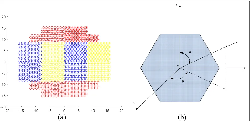
adaptive monopulse method can effectively alleviate such pressures and ensure angle estimation performance when limited number of interferences exist. An example of the subarray geometry is illustrated in Fig. 1a, in which regular and irregular subarray geometries are comprised. Nickel extends the adaptive monopulse technique to subarray and arbitrary array geometries and provides modified formulas of monopulse ratio. Then he systemati-cally analyzes the performance of the adaptive monopulse technique and extends it to space-time processing [2–5]. The monopulse angle estimation in presence of main lobe interference is discussed in [6], and a four-channel monopulse framework is proposed. The monopulse angle tracking problem in electronic countermeasures or jamming is investigated in [7]. The performance of monopulse angle tracking in noise or noise jamming is analyzed in [8]. In [9], a novel adaptive angle tracking loop filter is designed for three-dimensional monopulse angle tracking.
In the adaptive monopulse angle tracking, the signal of interest (SOI) may be present in any direction inside the 3dB beam scope, which may cause the distortion of the sum and difference patterns formed by linearly constrained minimum variance (LCMV) algorithm [10].
Fig. 1The diagrams of subarray and angle definition.aExample of the subarray geometry.bThe definition of(θ,ϕ). The array locates in the zoy plane
Therefore, the adaptive monopulse algorithm should be robust to the look direction error. The methods in [11–21] are robust adaptive beamforming (RAB) methods. A shrinkage-based diagonal loading (DL) method is pro-posed in [11]. The loading level to the covariance matrix can be determined automatically. In [12], the adaptive beamforming is transformed to a fast Fourier trans-form based weighted pattern synthesis problem with con-straints on beamwidth and peak side lobe level. Robust adaptive beamforming methods based on steering vector estimation (SVE) can be found in [13–21]. The SVE-based methods can achieve high performance by adjusting the pattern look direction automatically to the SOI direc-tion. The robust Capon beamformer (RCB) and doubly constrained robust Capon beamformer (DCB) in [13, 14] can estimate the steering vector of SOI and the SOI power based on an uncertainty set. A modified cost func-tion is proposed in [15] utilizing the subspace-associated power component rather than all power components in the covariance matrix. In [16–18], the optimization cost functions for estimating the SOI steering vector are modified and then transformed into convex optimization problems. In [19], the signal steering vector is estimated based on Oracle approximating shrinkage method. In [20], the SOI steering vector is estimated with the orthonor-mal projection approximation subspace tracking and sub-space projection. The uncertainty of the covariance matrix is considered to optimize the worst-case performance. In [21], a steering vector estimation method is devel-oped based on maximum output power criterion and subspace rotation.
However, the previous SVE-based robust beamforming methods are unsuitable for subarray robust monopulse beamforming for the following reason. In the monopulse beamforming, the pattern look direction must be exactly known. The difference beams are formed using the look direction to guarantee the linearity of the monopulse ratios near the pattern look direction. When the previous SVE-based methods are applied to monopulse beamform-ing, the pattern look direction is changed. The actual look direction needs to be calculated utilizing the estimated steering vector. However, the look direction is much dif-ficult to be calculated from the subarray steering vector. In a subarray antenna with irregular subarray geometries, the exact position of the phase center of each subarray is needed when calculating the direction. It is known that, for an irregular subarray, the phase center is changed according to the direction of the incoming signal and is difficult to locate.
Therefore, we can conclude that the robust beamform-ing methods which adjust the pattern look direction are not suitable for robust monopulse beamforming on subar-ray antenna. The main lobe constraint-based robust adap-tive beamforming methods imposing multi-directional constraints [22, 23] and derivative constraints [24] will not change the look direction. However, the high cost of degrees of freedom (DOFs) makes them limited in the application to subarray monopulse beamforming.
lobes against distortion with fewer additional degrees of freedom. The constraint for main lobe maintenance is set approximating to the SOI steering vector. Thus, it can achieve good performance and cost only one DOF. Inspired by the steering vector estimation in [20], we use signal subspace projection to obtain the constraint for main lobe maintenance and subspace tracking to update the time-varying signal subspace of the data snapshots.
The method developed in this paper can be classi-fied into signal-processing-based beamforming methods. The eigenspace-based beamforming methods [25, 26] and reduced-rank beamforming methods [27–30] which use eigenvalue decomposition to obtain the projection sub-space and the reduced-rank subsub-space, the subsub-space track-ing based beamformtrack-ing methods [20, 31] and space-time adaptive processing methods [32–34] which utilize sub-space tracking to extract the signal subsub-space and inter-ference subspace, the training data processing methods [35–37] which preprocess the training data to improve the beamforming performance in nonhomogeneous clutter environments can be included in signal-processing-based beamforming methods. The adaptive radar detectors, as the adaptive beamformer orthogonal rejection test (ABORT)-like detector [38], detection schemes in mis-matched signal modes [39] and two-stage detection schemes [40], can utilize spatial and temporal data to adaptively discriminate the target signal from ECM signals in presence of noise. These methods can also be included in signal-processing-related beamforming techniques.
A crucial problem for our method is to estimate the dimension of the projection subspace especially when the number of signals is changed. For the proposed method, the optimal projection subspace is the signal subspace. The subspace tracking methods in [20] and [41–45] are not able to update the dimension of the signal subspace when subspace tracking. The dimension is fixed when subspace tracking. In this paper, we develop a power-associated method which maximizes the output signal to noise ratio (SNR) to determine the dimension of the pro-jection subspace. This power-associated method is incor-porated with the bi-iterative least-square (Bi-LS) subspace tracking [46] to adapt to the variation of the subspace dimension when subspace tracking.
The rest of this paper is organized as follows. In Section 2, we describe the signal model and the prob-lem we work on. In Section 3, the proposed algorithm is investigated according to the framework illustrated in Fig. 2b. The simulation results are presented in Section 4 to demonstrate the efficiency of the proposed algorithm. Section 5 concludes this paper.
2 Problem model
A plane array comprising M isotropic sensors is considered in this study. There are r spatial and
temporal uncorrelated narrowband plane wave signals incident on the array including the SOI and r −
1 interferences. The directions of these signals are
(θs,ϕs), in Fig. 1b. The output of themth sensor can be denoted by
xm(t)=s(t)ej2π(ymus+zmvs)/λ+
wheres(t)andjk(t)are the complex waveform of the SOI and the kth interference. λ is the wavelength. (ym,zm) denotes the position of themth sensor.nm(t)denotes the white Gaussian noise added on themth sensor. (u0,v0)
Then (2) can be represented in matrix form as
X(t)=AS(t)+N(t), (4) “H” are the matrix transpose and Hermitian transpose. a(u,v)is the steering vector provided by
a(u,v)= where “E[·]” denotes the mathematical expectation. The covariance matrix can be estimated recursively by
R(t)=βR(t−1)+(1−β)X(t)XH(t), (6)
where 0< β <1 is the forgetting factor.
In a subarray antenna array, each element is connected to a phase shifter. When the pattern look direction is
Fig. 2Block diagrams of (a) adaptive monopulse angle tracking loop.bThe proposed robust adaptive monopulse algorithm
P=diag(a0)= ⎡ ⎢ ⎢ ⎢ ⎢ ⎢ ⎢ ⎢ ⎢ ⎣
ej2π(y1u0+z1v0)/λ
ej2π(y2u0+z2v0)/λ
ej2π(y3u0+z3v0)/λ
. .. . ..
ej2π(yMu0+zMv0)/λ
⎤ ⎥ ⎥ ⎥ ⎥ ⎥ ⎥ ⎥ ⎥ ⎦
. (7)
where “diag(·)” operates a vector to a diagonal matrix. The subarray transformation matrix contains the phase shift terms and the subarray forming matrix [3]. It can be denoted by
Tb=PT, (8)
whereT is the subarray forming matrix with dimension
M×N, andNis the number of subarrays. Thenth(n = 1, 2,. . .,N) column of matrix T contains the elements summing up to thenth subarray.
The element data vectorX(t)is transformed into subar-ray output data vectorXb(t)with transformation matrix Tb, denoted by
Xb(t)=TbHX(t), (9)
where the subscript “b” denotes subarray. The subarray covariance matrix is provided by
Rxb(t)=TbHR(t)Tb. (10)
The monopulse processing can be done with subarray outputs [3]. For subarray monopulse, the LCMV-based beamforming weights can be obtained by solving the optimization problem as follows:
arg min
wn
wHnRxbwn
s.t. CHwn=f
where C is the constraint matrix and f denotes the response corresponding to C [10]. The adaptive weight vector can be denoted by:
wn=Rxb−1C
CHRxb−1C −1
f. (12)
For conventional LCMV-based monopulse algorithm [6], the response in the pattern look direction is con-strained, and the output power of the beamformer is minimized. If there are no look direction errors, the beam-former can provide the optimal SNR. When look direction error exists, the constraint mismatches the SOI direction, and the main lobe of the beam pattern may be distorted. The distortion obviously deteriorates angle estimation accuracy. In the rest of this paper, we use coventional LCMV algorithm to represent the conventional LCMV-based monopulse algorithm presented in [6].
In monopulse angle tracking, we assume that the length of one data block is a monopulse processing period, and the angle measurements in each processing period are averaged to achieve a steady performance. Since the monopulse processing period is a short period, the tar-get angle can be regarded unchanged. The tartar-get angle is tracked by the angle tracking loop filter from one monopulse processing period to the next. The block dia-gram of adaptive monopulse angle tracking loop is pre-sented in Fig. 2a. The pattern look direction in the current monopulse processing period is fixed and provided by the angle tracking loop filter. The loop filter utilizes the angle measurements in the current period and previous peri-ods, and predicts the most probable target angle in the next period. Because of the dynamic target movement, the SOI may be deviated from the assumed look direction, but inside the scope of the 3 dB beam width. This condition causes look direction error. The main lobes of the sum and difference beams formed by the conventional LCMV algo-rithm will be distorted, and angle estimation performance will be degraded. Therefore, a robust adaptive monopulse algorithm is incorporated into the monopulse angle track-ing loop, as illustrated in the dashed box in Fig. 2a. In this paper, we only focus on the adaptive monopulse beam-forming and angle estimation, and we do not discuss the angle tracking problem.
The block diagram of the proposed robust adaptive monopulse algorithm is shown in the dashed box in Fig. 2b. In Fig. 2b, aˆ(t) is the constraint of main lobe maintenance;ys,yuandyvare the outputs of sum and dif-ference beams. The signal subspace is updated through Bi-LS subspace tracking and the subspace dimension is determined by the power-associated method. Thereafter, the constraint of main lobe maintenance is obtained through subspace projection. Finally, a robust LCMV beamformer with constraints on main lobe maintenance and monopulse ratio curve is developed to obtain the
sum and difference beam outputs. The angle of SOI is estimated using sum and difference beam outputs.
3 The proposed robust adaptive monopulse algorithm
3.1 Robust LCMV beamformer with main lobe maintenance constraint (RMM-LCMV)
In order to relieve the pattern distortion caused by look direction error, an RMM-LCMV beamformer is devel-oped for forming the sum and difference beams. For con-ventional LCMV-based monopulse beamformer [6], the constraintCs and corresponding responsefs of the sum beam are constructed as
Cs=THba(u0,v0)=ab(u0,v0), (13)
fs=1, (14)
where,ab(u0,v0)is the subarray steering vector in direc-tion (u0,v0). Thus, the weight vector of the sum beam formed by the conventional LCMV algorithm (i.e.,ws) can be denoted by
For the difference beams, constraints are imposed on the slope of the monopulse ratio curve in the main lobe region and null point in the look direction to guarantee the linearity of the monopulse ratio curve. As in [6], con-straints are imposed on monopulse ratiosguandgvin the directions(u0±u,v0),(u0,v0±v)and(u0,v0)to satisfy azimuth difference beam and elevation difference beam responses in direction (u,v), respectively; Ku and Kv are the azimuth and elevation monopulse ratio slopes. For conventional LCMV-based monopulse algorithm, the constraintsCu,Cvand the corresponding responsesfu,fv of azimuth and elevation difference beams are denoted by
Cu=[ab(u0−u,v0),ab(u0,v0),ab(u0+u,v0)] , (18)
fu=
In our RMM-LCMV beamformer, an additional con-straint is applied to the sum and difference beams to maintain the main lobes. Assume that the constraint of main lobe maintenance at time indextisaˆ(t). Then, the responses corresponding to the above constraint are the responses of the quiescent sum and difference patterns on ˆ beam weight. wu0 and wv0 are the quiescent difference
beam weights denoted by
The main lobes of the sum and difference patterns formed by the RMM-LCMV beamformer can be main-tained distortionless. By incorporating the constraint of main lobe maintenance with conventional LCMV con-straints, the constraints of RMM-LCMV can be obtained. For the sum beam, the constraintCsrand the correspond-ing responsefsrof RMM-LCMV are denoted by
Csr=
The weight vector of the sum beam formed by RMM-LCMV can be obtained by
wsr(t)=R−xb1(t)Csr
CsrHR−xb1(t)Csr −1
fsr. (29)
For the difference beams, the constraint and response matrices of RMM-LCMV are constructed as
Cur =ab(u0−u,v0),ab(u0,v0),ab(u0+u,v0),aˆ(t)
where Cur and Cvr are the constraints of azimuth and elevation difference beams,furandfvrare the correspond-ing responses. The weight vectors of the difference beams formed by RMM-LCMV are computed as
wur(t)=R−xb1(t)Cur
The output of the sum and difference beams are denoted by,
ys(t)=wHsr(t)Xb(t), (36)
yu(t)=wHur(t)Xb(t), (37)
yv(t)=wHvr(t)Xb(t). (38)
The angle of SOI can be estimated by
us(t)=u0+realyu(t)ys(t))Ku, (39)
where real(·)denotes the real part of a complex value. The output power of the sum beam can be denoted by,
Ps=fHsr
In the LCMV beamformer, the output power is min-imized. When the interferences are suppressed by the adaptive beamforming, the output power of the sum beam mainly comprises the output power of the SOI and the noise. The ratio of the sum beam output powerPsto the output noise powerPnis denoted by
Ps
3.2 Computation of the main lobe constraint
For the subarray antenna, the constraints of main lobe maintenance need to be selected carefully to save DOFs. When expending only one additional DOF, we prove in the Appedix A that the constraint should be approximat-ing to the steerapproximat-ing vector of the SOI to obtain the highest output SNR. The steering vector of the SOI needs to be estimated rapidly. As is stated previously, estimating the angle of the SOI directly using the approximated steering vector is difficult in the cases that the subarray has arbi-trary geometry. Therefore, the monopulse processing is still needed for angle estimation.
Assume that the actual steering vector of SOI can be denoted by
ab=ab0+, (43)
whereab0is the steering vector of the assumed direction, i.e., the pattern look direction.is the error vector ofab0; it is caused by look direction error. The estimation value ofcan be obtained from [20] as follows,
ˆ
In the expressions above,Uˆnis the estimation of noise subspaceUn. WhenUnˆ approachesUn,ζ approximates to 0 andδapproaches 0. As a result,
ˆ
= −UnUH
nab0 (47)
By substituting (47) into (43), we can obtain
ab=ab0−UnUHnab0=
whereUsdenotes the signal subspace. (48) demonstrates the conclusion in [47, 48]. The steering vector of the SOI can be estimated by projectingab0to the signal subspace.
Assuming that the estimated steering vector isab, we use aˆ = ab as the constraint of main lobe mainte-nance. When the vectoraˆlocates in the subspace spanned by the steering vectors of interferences, aˆ is outside the main lobe scope. The projection valueaˆHab0 ab022 is much smaller than 1. We can exploit (49) as a judgement criterion ofaˆ.
whereρis a user-defined threshold. When the scope is set as the 3 dB beamwidth,ρcan be set to be 0.707.
3.3 Subspace tracking and subspace dimension estimation
In the proposed method, the signal subspace and the beamforming weights are updated in each snapshot to handle the dynamic cases. Conventional subspace decom-position method based on eigenvector decomdecom-position (EVD) is unable to update the signal subspace in real-time because of its high computational complexity. In this section, the Bi-LS subspace tracking [46] is exploited to track the dynamic signal subspace rapidly and accurately, and a power-associated method is developed to determine the dimension of the projection subspace.
The Bi-LS algorithm proposed in [46] computes the optimal low-rank matrix approximation. Bi-LS algorithm achieves fast singular value decomposition (SVD) based on QR-decomposition and Givens rotation to reduce the computational complexity. The steps of the exponen-tial window Bi-LS algorithm are shown in Table 1. In Table 1,Xb(t)is the subarray output data vector defined in Section 2;Ircis therc-dimensional identity matrix, where rcis the dimension of the tracked subspace;UB(t)is the obtained subspace.Xb(t)andUB(t)are the input and out-put of Bi-LS. Other symbols in Table 1 are intermediate variables of Bi-LS algorithm and detailed explanation of them can be found in [46]. The computational complexity of Bi-LS algorithm isNrc2+O(6Nrc).
When the dimensionrc = rmax+1, wherermaxis the largest possible number of signals,UB(t)converges to the right principal singular vectors ofXHb. TA(t)DA(t)TB(t) is the SVD of therc×rcupper triangular matrixRA(t). The largestrcsingular values ofXbcan be approximated
Table 1Exponential window Bi-LS algorithm
by the rcsingular values of RA(t), i.e., the diagonal ele-ments ofDA(t)[46]. The columns ofUB(t)are arranged so that the corresponding singular values are in descending order. If the dimension of the signal subspace isrd(t), the signal subspace can be denoted by the firstrd(t)columns ofUB(t).
For our proposed robust monopulse algorithm, select-ing the projection subspace fromUB(t)is a key problem. It can be concluded from Appendix A and (48) that the optimal projection subspace is the signal subspace. When the dimension of the projection subspace is equal to the dimension of the signal subspace, the output SNR can be maximized.
Generally, the MDL criterion [49] can be exploited to determine the dimension of the signal subspace. But in the proposed method, the following condition may limit its application to Bi-LS subspace tracking. The MDL crite-rion needs to use allNeigenvalues ofRxb(t)to determine the dimension. Assume that the eigenvalues of Rxb(t) are denoted by λ1 ≥ λ2 ≥ · · · ≥ λrc ≥ · · · ≥ λN. The largestrceigenvalues ofRxb(t)can be obtained from the diagonal elements ofDA(t), while the smallest N−rcones cannot be obtained by Bi-LS. The eigenval-ues obtained from Bi-LS denoted byλˆ1 ≥ ˆλ2 ≥ · · · ≥ ˆ
λrc, satisfies [λˆ1,λˆ2,· · ·,λˆrc]=μλ[λ1,λ2,· · ·,λrc], where μλ is a scalar. Since μλ is unknown in Bi-LS, we can-not use [λˆ1,λˆ2,· · ·,λˆrc] to obtain the remaining N − rc eigenvalues. An alternative approach is to regard the smallest N − rc eigenvalues equal to λˆrc. However, by this approach, they are larger than the actual eigenval-ues according to the eigenvalue distribution presented in [50]. This condition may fluctuate the performance of MDL criterion. The inaccurately estimated dimen-sion of the signal subspace may affect the computation of the main lobe constraint and may further deterio-rate the performance of main lobe maintenance and the output SNR.
In this section, determining the dimension of the pro-jection subspace is transformed to the maximization of the output SNR of the proposed beamformer by a power-associated method. When the output SNR is maximized, we can conclude from Appendix A and (48) that the pro-jection subspace is equal to the signal subspace. Then the subspace dimension can be obtained.
The maximization of the output SNR is equivalent to the maximization of the ratioPs/w22presented in (41) and (42). The dimension of the projection subspacerdcan be estimated by maximizingPs(k)/wk22with respect to the dimensionkand constraining the scope of constraint vectoraˆk,
In (50), wk denotes the sum beam weight when the dimension rd = k; aˆk = UBk(t)UHBk(t)ab0 = ˆak−1 + complex multiplications. Since the computation for eachk
is parallel, the computational complexity can be less than 3(rc+1)N2+12(rc+1)N+O(rc).
To further reduce the computational complexity of (50), we use the estimated eigenvalues to shrinkage the range of
k. Definerp = rd(t−1)+1. When there are additional
The steps of the subspace tracking and subspace dimen-sion estimation method are listed in Table 2. The power-associated method not only uses the information of eigenvalues and eigenvectors but also exploits the beam-forming outputs, which makes it more suitable for the proposed algorithm.
Table 2Subspace tracking and subspace dimension estimation
3.4 Steps of the proposed algorithm
The steps of the proposed robust adaptive monopulse algorithm are summarized below. For thetth snapshot:
(1) Track the signal subspace and determine the dimension of the projection subspace as listed in Table 2.
(2) The constraint for main lobe maintenance, i.e.,aˆ(t), can be obtained from step 1.aˆ(t)= ˆak, k=rd(t).
(3) Whenaˆ(t)− ˆa(t−1)22≤εandεis the error bound, compute the weight vector of the sum and difference beams of the proposed method at snapshot indext using (22)–(35).
(4) The outputs of adaptive sum and difference beams at snapshot indext are obtained by (36)–(38).
(5) Estimate the direction of the SOI using (39) and (40). Then average the angle measurements in one monopulse processing period.
As is stated previously, the proposed algorithm is developed for subarray adaptive monopulse in consider-ation of the limitconsider-ations of the SVE-based and main lobe constraint-based robust beamforming methods. It can also be applied to adaptive monopulse on the full array. The low cost of DOFs makes the proposed algorithm more suitable for subarray adaptive monopulse than previous methods. The proposed algorithm can also be utilized to adaptively form the sub-beams of the four quadrant monopulse approach (Section 2 in [3]) and the multiple squinted beams approach (Section 3 in [51]) to improve the robustness of these sub-beams to pattern look direc-tion error when the interference-plus-noise covariance matrix is unavailable.
4 Numerical simulations and discussions
The performance of the proposed robust adaptive monopulse algorithm is demonstrated by simulations based on the array geometry in Fig. 1a. The array work-ing in Ka band consists of 960 isotropic elements and is divided into 12 subarrays shown in different symbols and different colors. The array elements are at 0.58 wave-length separation and on a triangular grid. Each element is connected to a digital controlled phase shifter. The ele-ment noise is assumed to be additive white Gaussian noise with zero-mean and unit variance. For all simulations, the directions of the two interferences are(56◦, 0◦) and
(60◦, 40◦); The assumed pattern look direction is fixed at
(90◦, 0◦). The parameterαin Bi-LS is set to 0.999. Three scenarios are made to simulate the performance of the proposed algorithm.
Scenario 1 : The performance of the proposed method is simulated when the dimension of the signal subspace changes. The following assumptions are made: In the first
1000 snapshots, only the SOI is present. Whereas, SOI and two interferences are present in the following 2000 snap-shots. The direction of SOI is(91◦, 1◦). The performance of the power-associated method is simulated when SNR is set to 3,−10, and−20 dB. The interference-to-noise ratio (INR) is 35 dB. The deviation of the true and the tracked signal subspace is denoted by
D(t)=10log10Uˆ(t)Uˆ(t)H−U(t)U(t)H2
F (53)
whereU(t)andUˆ (t) are the true and the tracked signal subspace respectively;·Fdenotes the Frobenius norm.
The estimated dimension of the projection subspace, i.e.,rd(t), with the power-associated method is shown in Fig. 3a, b, and c. The estimated dimension can approx-imate the optimal dimension, i.e. the dimension of the signal subspace. When the interference is present in the snapshots aftert = 1000, the power-associated method can track the dimensional variation of the signal subspace. In Bi-LS, only the principal eigenvalues are obtained. This condition leads to the performance fluctuation of MDL criterion [49]. The tracking of the signal subspace shown in Fig. 3d can converge quickly after the actual dimension of the signal subspace is obtained.
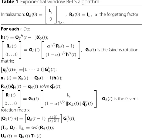
The convergence of the output signal to interference plus noise ratio (SINR) versus snapshots is also simulated when SNR=-20dB and -10dB. As illustrated in Fig. 4a, b, the output SINR of conventional LCMV algorithm [6] deteriorates obviously due to the look direction error; However, the output SINR of the proposed algorithm can converge quickly even when there exist additional inter-ferences in the snapshots after t = 1000. Comparing Fig. 4a and b with Fig. 4d, we can also find that the conver-gence speeds of the signal subspace when SNR =−20 dB and SNR =−10 dB are approximate, but the output SINR of SNR =−20 dB converges faster than that of SNR =−10 dB. For the SOI with higher input SNR, the look direction error has a greater impact on the adaptive beam pattern and the output SINR. Therefore, it requires more snap-shots for the proposed algorithm to obtain a high main lobe maintenance performance and output SINR.
Scenario 2: Firstly, we compare the output SINR of the proposed robust adaptive monopulse algorithm with those of the conventional LCMV algorithm [6], RCB [13], DCB [14], RAB with derivative constraints [24], RAB with multi-directional constraints [23] and the method in [47]. In the two simulations, the directions of SOI are
(91◦, 1◦) and (90.5◦, 0.5◦), respectively. The input SNR at the array elements varies from -30dB to 10dB, and input INR is 35dB larger than the input SNR. T =
Fig. 3The estimated signal subspace and its dimension.aSNR =−20 dB;bSNR =−10 B;cSNR = 3 dB;dSubspace estimation deviations
(89◦, 1◦), (91◦,−1◦), (91◦, 0◦), and (91◦, 1◦). The RAB with derivative constraints imposes 0, 1, and 2-ordered derivative constraints with respect touandv.
The comparisons of the output SINR are illustrated in Fig. 5a, b, respectively. RCB [13], DCB [14], and the method in [32] can obtain superior output SINR by auto-matically adjusting the look direction to SOI. But these methods are not designed for monopulse beamforming
and are not suitable for forming the difference beams of subarray monopulse. The output SINR of RAB with multi-directional constraints [23] is higher than that of RAB with derivative constraints [24]; however, both of them cannot obtain a consistent performance when the SOI is incident from(91◦, 1◦)and(90.5◦, 0.5◦). The output SINR of the proposed method is relatively lower than that of the method in [47] and higher than those of RCB and DCB.
Fig. 5Performance comparison of output SINR versus input SNR.a(θs,ϕs)=(91◦, 1◦);b(θs,ϕs)=(90.5◦, 0.5◦)
The proposed method only imposes two constraints for forming the sum beam, which is much less than the RAB with multi-directional constraints and RAB with deriva-tive constraints. The performance degradation of RAB with multi-directional constraints and RAB with deriva-tive constraints is caused by the deterioraderiva-tive constraint performance when the SOI direction is away from the constraints.
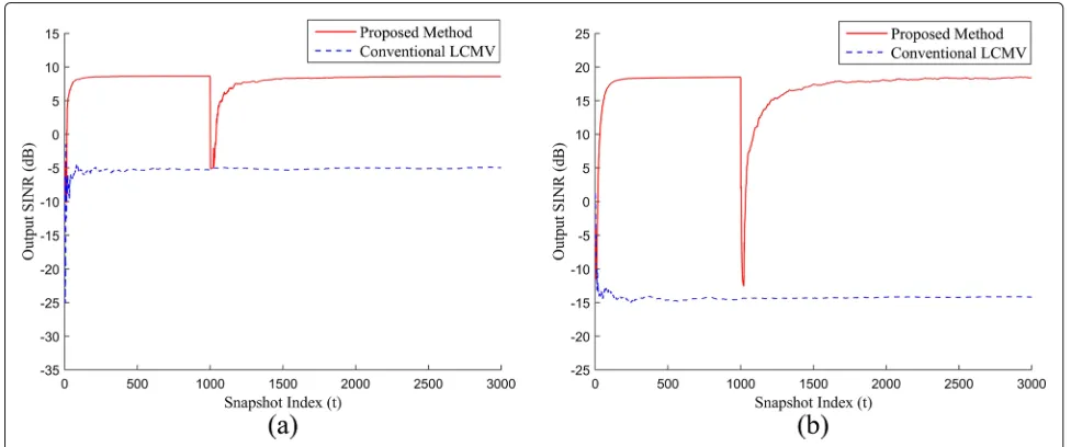
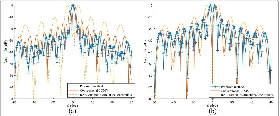
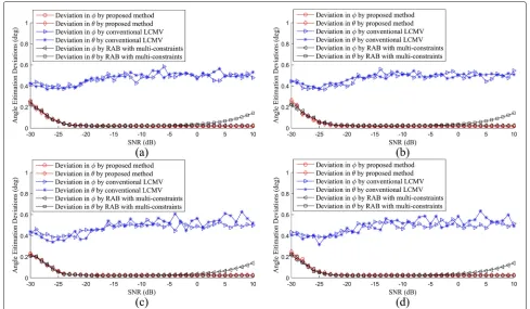
Then, the angle estimation performance of the proposed robust adaptive monopulse algorithm is compared with those of the conventional LCMV algorithm and RAB with multi-directional constraints. In the four simulations, the directions of SOI are set to (90.5◦,−0.5◦), (90.5◦, 0.5◦),
(89.5◦,−0.5◦), and(89.5◦, 0.5◦). The sum and difference beam patterns formed by these methods when the SOI direction is (89.5◦,−0.5◦) and input SNR is 10 dB are illutrated in Figs. 6 and 7. The beam patterns of conven-tional LCMV algorithm and RAB with multi-direcconven-tional contraints suffer from distortions; the beam patterns of the proposed algorithm can maintain distortionless. All of these algorithms can suppress the interferences. The angle estimation accuracy is illustrated in Fig. 8. The angle estimation accuracy of conventional LCMV algorithm deteriorates obviously due to the look direction error. The RAB with multi-directional constraints can maintain good performance in low SNR cases, but its performance
Fig. 7Sum and difference beam patterns inθof these methods;asum beam patterns;bdifference beam patterns
deteriorates when SNR is higher than −5 dB. The pro-posed method can still maintain high angle estimation accuracy when the SNR grows.
The results demonstrate that the proposed method can obtain higher performance than RAB with multi-directional constraints and RAB with derivative
constraints, and only costs one additional DOF compared to conventional LCMV algorithm.
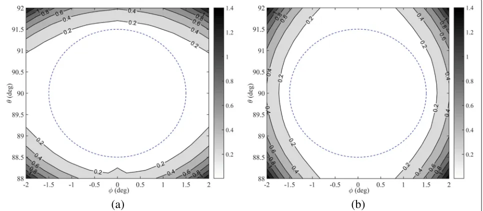
Scenario 3 : The angle estimation deviation versus SOI direction(θs,ϕs)is simulated. The 3dB beamwidth (BW) of the array is 3◦. In this simulation, the SNR is−10 dB
(a)
(b)
Fig. 9Angle estimation deviations versus SOI direction using the conventional LCMV algorithm;adeviation inθ;bdeviation inϕ
and INR is 30 dB.θsvaries from 88◦to 92◦andϕsvaries from −2◦ to 2◦. The angle estimation deviations of the proposed robust adaptive monopulse algorithm and con-ventional LCMV algorithm are simulated and compared. As illustrated in Fig. 9a, b, the angle estimation deviation of conventional LCMV algorithm is obviously larger than 0.1BW(0.3◦), and it deteriorates dramatically when the SOI is deviating from the look direction. The angle esti-mation deviation of the proposed algorithm is illustrated in Fig. 10a and 10b. The dashed lines in these figures donote the boundaries of the 3 dB BW. The deviation is lower than 0.1 BW within the 3 dB scope. The simulation
results demonstrate that the proposed algorithm can maintain high angle estimation accuracy in the mainlobe region when look direction error exists.
5 Conclusions
In consideration of the limitations of the SVE-based and main lobe constraint-based robust beamforming meth-ods for performing subarray monopulse beamforming, we develop a linearly constrained subarray robust adap-tive monopulse algorithm, which is different from previ-ous methods. The constraint of main lobe maintenance constructed by signal subspace projection expends only
(a)
(b)
Fig. 10Angle estimation deviations versus SOI direction using the proposed algorithm; thedashed linesdenote the boundaries of 3 dB beamwidth;
one DOF. Then, we develop a power-associated method to determine the dimension of the projection subspace and combine it with Bi-LS subspace tracking to adapt to the dimensional variation of the signal subspace. The power-associated method can achieve high performance when only the principal eigenvalues and the principal eigenvectors can be obtained in Bi-LS. Simulation results demonstrate that the proposed algorithm can maintain high anti-jamming capability and angle estimation per-formance when look direction error exists. The proposed algorithm can also be applied to adaptive monopulse on the full array. The low cost of DOFs makes it particularly suitable for the subarray adaptive monopulse technique.
Appendix A
In this Appendix, we prove that the highest output SNR of RMM-LCMV can be obtained by setting the constraint of main lobe maintenance as the SOI steering vector. The weight vector of RMM-LCMV can be denoted by
wsr =R−xb1Csr
whereRxb is nonsingular and positive semidefinite. If we define the quiescent weightWqas
Wq=Csr
as the projection operator of the column space of R−xb1/2Csr, and Bas a (N − 2) ×N-dimensional matrix which is orthogonal to the columns of Csr. BCsr = 0. Then, we can obtain
Substituting (59) into (56), we can obtain
wsr =R−xb1/2
The output of RMM-LCMV can be denoted by
ys(t)=wHsrXb(t)=WHqXb(t)−WHqRHxbBHBRxbBH−HBXb(t).
(61)
When the constraint of main lobe maintenance is set as the steering vector of SOI, i.e., aˆ = THba(us,vs), BCsr = 0 and Baˆ = 0. The component of SOI in WHqRHxbBHBRxbBH
−H
BXb(t)is negligible. Therefore, in (61), the SOI component is fully enhanced by the quies-cent weightWHqXb(t), and the interferences and the noise are suppressed. The output SNR of RMM-LCMV can be maximized.
Abbreviations
Bi-LS: Bi-iterative least-square; BW: Beamwidth; INR: Interference to noise ratio; LCMV: Linearly constrained minimum variance; PAST: Projection
approximation subspace tracking; RAB: Robust adaptive beamformer; SINR: Signal to interference plus noise ratio; SNR: Signal to noise ratio; SOI: Signal of interest; SVE: Steering vector estimation
Acknowledgements
This work is supported in part by the National Natural Science Foundation of China under grant 61501240, 61471196, 11273017 and 61401207; the College Graduate Scientific Research Innovation Fund in Jiangsu Province of China under Grant No. KYLX16 0447.
Authors’ contributions
SQ and XM designed the algorithm scheme. SQ and RZ performed the experiments and analyzed the experiment results. SQ, WS, and YH contributed to the manuscript drafting and critical revision. All authors read and approved the final manuscript.
Competing interests
The authors declare that they have no competing interests.
Received: 30 July 2016 Accepted: 26 January 2017
References
1. RC Davies, LE Brennan, LS Reed, Angle estimation with adaptive arrays in external noise filed. IEEE Trans Aerospace Electron Syst.AES-12(2), 179–185 (1976). doi:10.1109/TAES.1976.308293
2. U Nickel, Monopusle estimation with subarray-adaptive arrays and arbitrary sum and difference beams. IEE Proceedings-Radar Sonar Navig. 143(4), 232–238 (1996). doi:10.1049/ip-rsn:19960405
3. U Nickel, Overview of generalized monopulse estimation. IEEE Aerospace Electron. Syst. Mag.21(6), 27–56 (2006). doi:10.1109/MAES.2006.1662039 4. U Nickel, Performance analysis of space-time adaptive monopulse.
ELSEVIER Signal Process.84(9), 1561–1579 (2004). doi:10.1016/j.sigpro.2004.05.025
6. Yu Kai-Bor, DJ Murrow, Adaptive digital beamforming for angle estimation in jamming. IEEE Trans. Aerosp. Electron. Syst.37(2), 508–523 (2001). doi:10.1109/7.937465
7. WR Blanding, W Koch, U Nickel, Adaptive phased-array tracking in ECM using negative information. IEEE Trans. Aerosp. Electron. Syst.45(1), 152–166 (2009). doi:10.1109/TAES.2009.4805270
8. AD Seifer, Monopulse-radar angle tracking in noise or noise jamming. IEEE Trans. Aerosp. Electron. Syst.28(3), 622–638 (1992). doi:10.1109/7.256285 9. J Bing-bing, S Wei-xing, Z Ren-li, et al., Adaptive angle tracking loop
design based on digital phase-locked loop. ELSEVIER Signal Process.123, 221–236 (2016). doi:10.1016/j.sigpro.2016.02.002
10. OL Frost, An algorithm for linearly constrained adaptive array processing. Proc. IEEE.60(8), 926–935 (1972). doi:10.1109/PROC.1972.8817 11. Lin Du, Jian Li, Petre Stoica, Fully automatic computation of diagonal
loading levels for robust adaptive beamforming. IEEE Trans. Aerosp. Electron. Syst.46(1), 449–458 (2010). doi:10.1109/TAES.2010.5417174 12. K Yang, Z Zhao, Robust adaptive beamforming using an iterative FFT
algorithm. ELSEVIER Signal Process.96, 253–260 (2014). doi:10.1016/j.sigpro.2013.09.003
13. J Li, P Stoica, Z Wang, On robust Capon beamforming and diagonal loading. IEEE Trans. Signal Process.51(7), 1702–1715 (2003). doi:10.1109/TSP.2003.812831
14. J Li, P Stoica, Z Wang, Doubly constrained robust Capon beamformer. IEEE Trans. Signal Process.52(9), 2407–2423 (2004).
doi:10.1109/TSP.2004.831998
15. Y-H Choi, Doubly constrained robust beamforming method using subspace-associated power components. Digitial Signal Process.42, 43–49 (2015). doi:10.1016/j.dsp.2015.04.006
16. A Hassanien, SA Vorobyov, KM Wong, Robust adaptive beamforming using sequential quadratic programming: An iterative solution to the mismatch problem. IEEE Signal Process. Lett.15, 733–736 (2008). doi:10.1109/LSP.2008.2001115
17. A Khabbazibasmenj, SA Vorobyov, A Hassanien, Robust adaptive beamforming based on steering vector estimation with as little as possible prior information. IEEE Trans. Signal Process.60(6), 2974–2987 (2012). doi:10.1109/TSP.2012.2189389
18. Y Gu, A Leshem, Robust adaptive beamforming based on interference covariance matrix reconstruction and steering vector estimation. IEEE Trans. Signal Process.60(7), 3881–3885 (2012).
doi:10.1109/TSP.2012.2194289
19. H Ruan, RC de Lamare, Robust adaptive beamforming using a low-complexity shrinkage-based mismatch estimation algorithm. IEEE Signal Process. Lett.21, 60–64 (2014). doi:10.1109/LSP.2013.2290948 20. B Liao, S-C Chan, K-M Tsui, Recursive steering vector estimation and
adaptive beamforming under uncertainties. IEEE Trans. Aerosp. Electron. Syst.49(1), 489–501 (2013). doi:10.1109/TAES.2013.6404116
21. X Wang, J Xie, Z He, H Li, A robust generalized sidelobe canceller via steering vector estimation. J. Adv. Signal Process.2016(59), 1–11 (2016). doi:10.1186/s13634–016-0358-7
22. JW Xu, GS Liao, SQ Zhu, Robust LCMV beamforming based on phase response constraint. Electron. Lett.48(20), 1304–1306 (2012). doi:10.1049/el.2012.2619
23. AK Steele, Comparison of directional and derivative constraints for beamformers subject to multiple linear constraints. IEE Proc. F Commun. Radar Signal Process.130(1), 41–45 (1983). doi:10.1049/ip-f-1.1983.0008 24. GL Fudge, DA Linebarger, Spatial blocking filter derivative constraints for
the generalized sidelobe canceller and MUSIC. IEEE Trans. Signal Process. 44(1), 51–61 (1996). doi:10.1109/78.482011
25. DD Feldman, LJ Griffiths, A projection approach to robust adaptive beamforming. IEEE Trans. Signal Process.42(4), 867–876 (1994). doi:10.1109/78.285650
26. DD Feldman, An analysis of the projection method for robust adaptive beamforming. IEEE Trans. Antennas Propag.44(7), 1023–1030 (1996). doi:10.1109/8.504311
27. DW Tufs, R Kumaresan, I Kirsteins, Data adaptive signal estimation by singular value decomposition of a data matrix. Proceedings of the IEEE. 70(6), 684–685 (1982). doi:10.1109/PROC.1982.12367
28. SD Berger, BM Welsh, Selecting a reduced-rank transformation for STAP-a direct form perspective. IEEE Trans. Aerosp. Electron. Syst.35(2), 722–729 (1999). doi:10.1109/7.766952
29. JS Goldstein, IS Reed, Subspace selection for partially adaptive sensor array processing. IEEE Trans. Aerosp. Electron. Syst.33(2), 539–544 (1997) 30. R Shan, C Fan, X Huang, A new reduced-rank STAP method based on
cross spectral defined by range cell echo. Proc. Int. Conf. Wireless Commun. Signal Process, 1–3 (2009). doi:10.1109/WCSP.2009.5371707 31. Y-H Choi, Robust adaptive beamforming method using principal
eigenpairs with modification of PASTd. Digital Signal Process.23(2), 595–600 (2013). doi:10.1016/j.dsp.2012.08.014
32. M Shen, D Zhu, Z Zhu, Reduced-rank space-time adaptive processing using a modified projection approximation subspace tracking deflation approach. IET Radar Sonar Navi.3(1), 93–100 (2009).
doi:10.1049/iet-rsn:20080045
33. X Yang, Y Liu, Y Sun, T Long, Improved PRI-staggered space-time adaptive processing algorithm based on projection approximation subspace tracking subspace technique. IET Radar, Sonar, Navi.8(5), 449–456 (2014). doi:10.1049/iet-rsn.2013.0175
34. X Yang, Y Sun, T Zeng, T Long, TK Sarkar, Fast STAP method based on PAST with sparse constraint for airborne phased array radar. IEEE Trans. Signal Process.64(17), 4550–4561 (2016). doi:10.1109/TSP.2016.2569471 35. DJ Rabideau, AO Steinhardt, Improved adaptive clutter cancellation
through data-adaptive training. IEEE Trans. Aerosp. Electron. Syst.35(3), 879–891 (1999). doi:10.1109/7.784058
36. B Dai, T Wang, T Bai, J Wu, Z Bao, Training data selection method for adaptive beamforming. Electron. Lett.50(17), 1242–1244 (2014). doi:10.1049/el.2014.2024
37. B Dai, T Wang, J Wu, et al., Adaptively iterative weighting covariance matrix estimation for airborne radar clutter suppression. Signal Process. 106, 282–293 (2015). doi:10.1016/j.sigpro.2014.07.024
38. F Bandiera, A Farina, D Orlando, G Ricci, Detection algorithms to discriminate between radar targets and ECM signals. IEEE Trans. Signal Process.58(12), 5984–5993 (2010). doi:10.1109/TSP.2010.2077283 39. F Bandiera, D Orlando, G Ricci,Advanced radar detection schemes under
mismatched signal models. (Morgan and Claypool Publishers, New York, 2009)
40. A De Maio, D Orlando, Feature article: a survey on two-stage decision schemes for point-like targets in Gaussian interference. IEEE Aerospace Electron. Syst. Mag.31(4), 20–29 (2016). doi:10.1109/MAES.2016.150092 41. B Yang, Projection approximation subspace tracking. IEEE Trans. Signal
Process.43(1), 95–107 (1995). doi:10.1109/78.365290
42. R Badeau, B David, G Richard, Fast approximated power iteration subspace tracking. IEEE Trans. Signal Process.53(8), 2931–2941 (2005). doi:10.1109/TSP.2005.850378
43. JF Yang, M Kaveh, Adaptive eigensubspace algorithms for direction or frequency estimation and tracking. IEEE Trans. Acoust. Speech Signal Process.36(2), 241–251 (1988). doi:10.1109/29.1516
44. XG Doukopoulos, GV Moustakides, Fast and stable subspace tracking. IEEE Trans. Signal Process.56(4), 1452–1465 (2008)
45. R Wang, M Yao, D Zhang, H Zou, A novel orthonormalization matrix based fast and stable DPM algorithm for principal and minor subspace tracking. IEEE Trans. Signal Process.60(1), 466–472 (2012).
doi:10.1109/TSP.2011.2169406
46. S Ouyang, Y Hua, Bi-iterative least-square method for subspace tracking. IEEE Trans. Signal Process.53(8), 2984–2996 (2005).
doi:10.1109/TSP.2005.851102
47. F Huang, W Sheng, X Ma, Modified projection approach for robust adaptive array beamforming. ELSEVIER Signal Process.92, 1758–1763 (2012). doi:10.1016/j.sigpro.2012.01.015
48. L Chang, CC Yeh, Performance of DMI and eigenspace-based beamformers. IEEE Trans. Antennas Propag.40(11), 1336–1347 (1992). doi:10.1109/8.202711
49. M Wax, T Kailath, Detection of signals by information theoretic criteria. IEEE Trans. Acoust. Speech Signal Process.33(2), 387–392 (1985). doi:10.1109/TASSP.1985.1164557
50. RR Nadakuditi, A Edelman, Sample eigenvalue based detection of high-dimensional signals in white noise using relatively few samples. IEEE Trans. Signal Process.56(7), 2625–2638 (2008)
51. KB Yu, MF Fernández, in2014 IEEE Radar Conference. Digital beamforming of sub-aperture cluster beams with enhanced angle estimation capabilities, (Cincinnati, OH, 2014), pp. 0239–0244.