Chip-Level Channel Equalization in WCDMA Downlink
Kari Hooli
Centre for Wireless Communications, P.O. Box 4500 FIN-90014, University of Oulu, Finland Email: [email protected]
Markku Juntti
Centre for Wireless Communications, P.O. Box 4500 FIN-90014, University of Oulu, Finland Email: [email protected]
Markku J. Heikkil ¨a
Nokia Mobile Phones, P.O. Box 50, 90571 Oulu, Finland Email: [email protected]
Petri Komulainen
Nokia Mobile Phones, P.O. Box 50, 90571 Oulu, Finland Email: [email protected]
Matti Latva-aho
Centre for Wireless Communications, P.O. Box 4500 FIN-90014, University of Oulu, Finland Email: [email protected]
Jorma Lilleberg
Nokia Mobile Phones, P.O. Box 50, 90571 Oulu, Finland Email: [email protected]
Received 14 August 2001 and in revised form 7 March 2002
The most important third generation (3G) cellular communications standard is based on wideband CDMA (WCDMA). Receivers based on TDMA style channel equalization at the chip level have been proposed for a WCDMA downlink employing long spread-ing sequences to ensure adequate performance even with a high number of active users. These receivers equalize the channel prior to despreading, thus restoring the orthogonality of users and resulting in multiple-access interference (MAI) suppression. In this paper, an overview of chip-level channel equalizers is delivered with special attention to adaptation methods suitable for the WCDMA downlink. Numerical examples on the equalizers’ performance are given in Rayleigh fading frequency-selective channels.
Keywords and phrases:WCDMA, multiple-access interference, channel equalization.
1. INTRODUCTION
The air interface of universal terrestrial radio access (UTRA), the most important third generation (3G) cellular mobile communications standard, is based on wideband code-division multiple-access (WCDMA). In 3G, cellular net-works downlink capacity is expected to be more crucial than uplink capacity due to asymmetric capacity require-ments, that is, the downlink should offer higher capacity than the uplink [1]. Therefore, the use of efficient down-link receivers is important. In order to avoid performance degradation, near-far resistant (or multiuser) receivers [2]
In a synchronously transmitted downlink employing or-thogonal spreading codes, MAI is mainly caused by mul-tipath propagation (neighboring cells form another source of MAI). Due to the nonzero cross-correlations between spreading sequences with arbitrary time shifts, there is in-terference between propagation paths (or Rake fingers) after despreading, causing MAI. With a moderate or high number of active users, the performance of a Rake receiver becomes limited by interpath MAI. If the received chip waveform, dis-torted by the multipath channel, is equalized prior to correla-tion by the spreading code or matched filtering, there is only a single path in the despreading. With orthogonal spreading sequences the equalization effectively retains, to some extent, the orthogonality of users lost due to multipath propagation, thus suppressing MAI. Since the signal is equalized at the chip level, not on the symbol level, they can also be applied in systems using long spreading sequences. Such a receiver con-sists of a linear equalizer followed by a single correlator and a decision device.
The chip-level channel equalizer has proven to be one of the most promising terminal receivers for a WCDMA/FDD downlink. It has drawn attention and inspired numerous publications in recent years. Chip-level equalization has been treated in [5, 6, 7, 8, 9, 10]. It has been addressed in mis-cellaneous contexts also earlier, as in [11]. Although chip-level equalization resembles at first glance the classical linear TDMA-type equalization (time-division multiple access), it has several aspects characteristic for CDMA or 3G networks, thus making it an interesting research topic. These aspects include efficient adaptation of the equalizer due to diff er-ent training signals in CDMA, soft hand-over, and trans-mit diversity. Chip-level equalization was considered with soft hand-over in [12, 13], and with different transmit diver-sity schemes in [14, 15]. Performance evaluations of chip-level equalizers with channel coding have been presented in [16], and with adaptive equalizers in [17, 18]. A chip equalizer based receiver for a CDMA downlink employ-ing a long scramblemploy-ing sequence and nonorthogonal chan-nelization sequences was proposed in [19]. A large vari-ety of adaptive chip-level equalizers have also been pre-sented and studied in a number of publications, includ-ing, for example, [20, 21, 22, 23, 24, 25, 26, 27]. A diff er-ent approach for improving the performance of downlink receiver, that is, generalized Rake receiver, is discussed in [28].
The purpose of this paper is to provide an overview of chip-level equalization and on the adaptation methods pro-posed for chip-level equalizers. The possible performance gains offered by the chip-level channel equalizers are ad-dressed, and the performance of six different adaptive chip equalizers are compared in a frequency-selective fading chan-nel. The paper is organized as follows. The system model is defined in Section 2, and the zero-forcing and LMMSE equalizers with perfect knowledge of the channel are ad-dressed in Section 3. The adaptive versions of chip-level equalizers are discussed in Section 4. Numerical examples for the receivers are presented in Section 5, followed by conclud-ing remarks in Section 6.
2. SYSTEM MODEL
In this section, we present the system model used in defining the receivers in the sequel. Only a single-base station and a single-receive antenna are included into the system model.1 With a single-receive antenna, signal processing is restricted to the time domain. Due to the lack of spatial characteristics in the signal structure, moderate level other cell interference can be considered to be included in the white Gaussian noise. Since the downlink is considered, all signals are syn-chronously transmitted through the same multipath chan-nel. The complex envelope of the received signal at the user terminal can be written as
r(t)= user’s symbols in the observation window,2Lis the number of paths,Akis the average received amplitude ofkth user,b(km) is themth symbol ofkth user,cl(t) is the time-variant com-plex channel coefficient oflth path,s(km)(t) is the spreading waveform of mth symbol ofkth user given by convolution of spreading sequence and chip waveform,Tkis the symbol interval for kth user, τl is the delay oflth path, andn(t) is complex white Gaussian noise process.
The discrete-time received signal after appropriate down-conversion and filtering can be written as
r= number of chips in the observation window.3 In (2),D =
[d(1)1 , . . . ,d(1)L ,d(2)1 , . . . ,dL(Nc)]∈RNcNs×LNc is a path delay and
chip waveform matrix where the column vectord(ln)contains samples from appropriately delayed chip waveform for the
lth path ofnth chip,C=diag(c(1), . . . ,c(Nc))∈CLNc×Nc is a block diagonal channel matrix with column vectorc(n)∈CL containing the time-variant channel coefficients forLpaths. The term DC models the combination of chip waveform and multipath channel and is common for all users;Sk = diag(s(1)k , . . . ,sk(Mk)) ∈ CNc×Mk is a block diagonal spread-ing sequence matrix where column vectors(km) ∈ΞGk
s ,Ξsis the chip alphabet, contains the spreading sequence for the
kth user’smth symbol with a spreading factor Gk. The cell specific scrambling sequence is included in the spreading sequences, that is, Sk = SSc(t)Sk,Ch, where the scrambling
1It is straightforward to extend the model to include multiple-base
sta-tions or receive antennas.
2Thus the model allows multiple transmission rates. 3Nc=G
kMk, whereGkis the spreading factor forkth user. The product
sequence is in the diagonal matrix SSc(t) and the block di-agonal matrix Sk,Ch contains the user specific channeliza-tion sequence for thekth user. The sequences are normal-ized so that SHkSk = I, and they are also orthogonal, that bet, contains the transmitted symbols ofkth user, assumed to be i.i.d. with unit variance, andn∈CNcNscontains samples from a white complex Gaussian noise process with covari-anceCnn=σn2INcNs.
3. RECEIVERS
The chip-level version of zero-forcing and LMMSE equaliz-ers as well as the conventional Rake receiver are presented in this section. As mentioned earlier, the multipath channel is equalized prior to despreading in the chip equalizer receivers, thus restoring to some extent the orthogonality of channel-ization codes and suppressing MAI. This means that the term
DCin (2) is suppressed. The equalizer is followed by a single correlator and decision device.
The equalizers treated in this paper are all linear, due to the difficulties faced when nonlinear equalizers are consid-ered for chip-level equalization. The detection of the desired user at chip-level is highly counter-intuitive, since it would ignore the processing gain associated with spreading. Thus, the desired output signal of a chip-level equalizer is the to-tal transmitted signal from the base station, that is, the sum of all users’ signals. The nonlinear equalizers rely on prior knowledge of constellation of the desired signal. This infor-mation is not easily available at the terminal, since the con-stellation of all users’ signal sum is a high-order QAM with uneven spacing. The constellation order changes at frame rate (100 Hz) with the changing number of active users, and the spacing in the constellation changes at power control rate (1.5 kHz). However, for example, in [29] an interesting non-linear equalizer based on soft decision cancelling was pre-sented for a WCDMA downlink.
With the introduced system model, the decision variable of the Rake receiver for arbitrary selected user 1 is given by
yR=SH1CHDHr, (3)
that is, the received signal is filtered by the chip waveform, appropriately delayed and weighted with channel coefficients in the Rake fingers, coherently combined and finally de-spread. The abnormal order of the maximal ratio combin-ing (MRC) and despreadcombin-ing has no effect on receiver perfor-mance due to the linearity of operations.
When a zero-forcing equalizer is applied, the tap coeffi -cients of the equalizer are given by
WZ=DC
CHDHDC−1. (4)
4The use ofAkallows power differences between different symbols of an
individual user. In here, constant powerA2kis assumed.
The first term on the right-hand side, DC, performs chip waveform matched filtering, and is followed by the conven-tional zero-forcing equalizer [30, 31]. The decision variable after despreading can be written as
yZ =SH1WHZr=SH1
CHDHDC−1CHDHr. (5)
In (4), the zero-forcing equalizer is given in block form (WZ ∈CNcNs×Nc). The filter form of the zero-forcing equal-izer is obtained by taking a middle column fromWZ.5
The second considered equalizer, an LMMSE chip-level equalizer, can be obtained by solving
WL=arg min
where E[·] denotes expectations, and the minimization is carried out elementwise. By estimating the sum of all users’ chips instead of the chips of a single user, the signal-to-noise ratio (SNR) faced in the estimation problem is significantly improved. It should also be noted that the chip equalizer does not try to suppress other users’ signals at the chip level, but just restores the orthogonality of users. It can be shown that for (6)WLis given by [32]
resulting in the decision variable
yL=SH1WHLr
The standard symbol-level LMMSE equalizer [3, 4], fea-sible for DS-CDMA systems employing short spreading se-quences, is defined for user 1 by
WLs=arg min
which results in the decision variable
yLs=A
Comparing (8) and (10), we can see that, for a given ob-servation window, the chip-level and symbol-level LMMSE receivers are equal up to a scalar. This is an expected re-sult, since the LMMSE estimator commutes over linear (or affine) transformations [32], like despreading. The equal per-formance of LMMSE receivers was verified numerically in [33].
As seen from (7), the LMMSE solution of a chip-level equalizer depends on the spreading sequences of all users with the period of a long scrambling code. This follows from the dependency between consecutive chips to be es-timated. The optimal solution changes from chip to chip, and an adaptive chip-level equalizer will not reach the exact optimal tap coefficients. The adaptive versions of chip-level LMMSE equalizer are built on simplifications that (i) spread-ing sequences are random, and (ii) the random spreadspread-ing se-quences are white and independent from those of other users. The simplifications are unavoidable due to the nonstationar-ity of the LMMSE solution in (7).6The LMMSE chip-level equalizer derived according to the simplifications (or false as-sumptions) is given by
wheres2denotes the square value of chip. The decision vari-able after correlation with the spreading sequence is given by
y˜L=SH1W˜HLr
The performance losses caused by the aforementioned sim-plifications can be assessed by comparing the performances of the equalizers given in (7) and (11) [33, 34]. Again, the chip-level equalizer in (11) is in a block form, and the equal-izer is obtained in filter form by taking a middle column from
˜
WL.
4. ADAPTATION METHODS
In this section, several methods for adapting chip-level equalizer are discussed. WCDMA terminal receivers have access to two-pilot signals, one carried on the continu-ous common pilot channel (CPICH) and another carried on the time-multiplexed dedicated physical control chan-nel (DPCCH). The high content of pilot signals combined with the DS-CDMA signal structure allows accurate chan-nel response estimation in the terminal. On the other hand, pilot signals form only a small portion of the received sig-nal. Thus, for the adaptation of the equalizer, a good es-timate of the channel response and a relatively weak but time-continuous reference signal are available. As a result, several adaptation methods that are not typical with linear TDMA equalizers have been proposed for chip-level equal-ization. In [22] equalizing was proposed to be carried out by an adaptive chip separation filter, which is based on blindly decorrelating the multipath combined chip estimates. The method applies to systems employing long random scram-bling codes, in which the original transmitted multiuser chip
6The LMMSE solution cannot be considered to be cyclostationary, since
the channel is likely to change during the spreading sequence period of 10 ms.
sequence is also uncorrelated. Kalman filtering was applied for chip-level equalization in [25]. Constrained minimum output energy equalizers, minimizing the energy in the sub-space of unused spreading sequences, are proposed for IS-95 and CDMA2000 terminals in [21, 35, 36, 37]. However, they require knowledge of unused spreading sequences, thus im-posing restrictions too strict for radio resource management in WCDMA/FDD systems.
The most straightforward adaptation, that is, the least mean square (LMS) adaptation based on the common pi-lot channel (CPICH), is studied in Section 4.1. The use of a pilot channel as a reference signal was suggested in [7], but the adaptation was not studied any further. In [19], a pilot channel was proposed to be used with the stabilized fast a-posteriori error sequential technique (SFAEST) and in [38] with the multistage nested Wiener filter (MSNWF). In the following, the adaptation is done at chip rate. The adapta-tion can be performed also at symbol rate, as shown in [39].7 The use of Griffiths’ algorithm [40] with a chip-level equal-izer is presented in Section 4.2, followed by the introduction of a minimum output energy equalizer constrained with the channel response in Section 4.3. Equalizers consisting of a separate filter and Rake receiver are referred to as prefilter-Rake equalizers in the sequel [20, 27]. In Section 4.4, adap-tive versions of a prefilter-Rake based on square-root RLS, the Levinson algorithm and Griffiths algorithm are studied. Finally, the properties of adaptive equalizers are compared in Section 4.5.
4.1. Common pilot channel based adaptation
In the adaptive equalizers discussed in Sections 4.1, 4.2, and 4.3, the appropriately sampled received signal is filtered by the chip waveform, equalized and correlated with the spread-ing sequence. The decision variable for user 1 after correla-tion with the spreading sequence is given byy=SH1z, where vectorzcontains equalizer outputs for corresponding chip intervals. Thenth element ofzisw(n)Hr¯(n), wherew(n)∈
C2D+1 contains the equalizer taps and ¯r(n)= [r(nN s−D),
. . . , r(nNs), . . . , r(nNs+D)]T contains output samples from
the chip waveform matched filter within the equalizer atnth chip interval. The number of samples per chip is given byNs and 2D+ 1 is the number of equalizer taps.
The most straightforward solution to the adaptation of a chip-level equalizer is to use the normalized LMS (NLMS) algorithm with a common (or dedicated) pilot channel as a reference signal. The receiver is depicted in Figure 1, and re-ferred to as a CPICH trained equalizer in the following. The NLMS adaptation step for the equalizer is [41, Chapter 9]
wC(n+ 1)=wC(n) +µ between the equalizer output and reference signals(n).
7When comparing results, one should pay attention to the channel
r Chip waveform ¯r z y
matched filter Equalizer Correlator
LMS + ×
−
Pilot signal
Spreading sequence
Figure1: CPICH trained LMS equalizer.
Since the adaptation is carried out at chip level, the chips of CPICH are used as reference samples. It should be noted that although the errore(n) contains the signals of all active users, also the desired one, the equalizer does not suppress them due to the pseudorandomness of spreading codes. The relatively large error signal values also mean that the SNR in the adaptation is low, and small adaptation step sizes are required to provide sufficient averaging. The small values of
µare partially compensated by a high adaptation rate.
4.2. Griffiths’ algorithm adapted equalizer
Several adaptation algorithms are obtained through different approximations of the gradient vector of the mean square er-ror cost function
J=Ed−wHr¯2, (14)
wheredis the desired output of the equalizer. The gradient vector is given by
∇J= −2Ed∗¯r+ 2E¯r¯rHw, (15)
where E[d∗r¯] is the cross-correlation vector between the in-put signal ¯r and the desired output of the equalizer, and E[¯rr¯H]=Ris the covariance matrix of the input signal [41]. For example, the aforementioned standard LMS algorithm is obtained by replacing expectations with instantaneous esti-mates, that is, signal vectors ¯r(n).
In [23], the Griffiths algorithm is used for the adaptation of a chip-level channel equalizer. The algorithm is obtained from (15) by replacing the cross-correlation vector E[d∗¯r] with ˆp, the channel response estimate. Instantaneous esti-mates are used for the covariance matrixR, as in the LMS algorithm. The resulting adaptation is
wG(n+ 1)=wG(n)−µ
z∗(n)¯r(n)−pˆ, (16)
whereµis the adaptation step size andz(n) is the equalizer output atnth chip interval.
4.3. CR-MOE equalizer
In the channel-response constrained minimum-output-energy (CR-MOE) equalizer [26], the equalizer is decom-posed into a constraint (or nonadaptive) component and an adaptive component. This is the well-known idea of the
gen-eralized side-lobe canceler, described, for example, in [41, Chapter 5]. The same approach has been applied in blind MOE multiuser receivers, in which the spreading sequence of a desired user is used as the constraint [2, 42]. As men-tioned, the equalizer is decomposed into two parts, that is,
wM =pˆ+x. The channel response estimate ˆpis used as the nonadaptive part, and the adaptive partxis constrained onto a subspace orthogonal to ˆpto avoid suppression of the de-sired signal. The mean square errorJ =E|d−wHMr¯|2can be written asJ =E[d2]−2 ˆpHpˆ+ ( ˆp+x)HE[¯r¯rH]( ˆp+x). For a given ˆp, the mean square error is minimized by minimiz-ing the last term ofJ, that is, the equalizer output energy— other terms of J are not affected by vectorx. To obtain an adaptive algorithm for x, stochastic approximation is ap-plied to the gradient ∇J = E[¯rr¯H]( ˆp+x) taken with re-spect tox. The orthogonality condition is maintained at each iteration by projecting the gradient onto the subspace or-thogonal to ˆp. The orthogonal component of the gradient is
∇J˜⊥pˆ =r¯−pˆpˆHr¯ ˆ
pHpˆ
¯
rHwM, (17)
and the resulting adaptation algorithm becomes
x(n+ 1)=x(n)−µz∗(n)¯r(n)−zp(n) ˆp
, (18)
where zp(n) = pˆHr¯(n)/( ˆpHpˆ) is the output of the channel response filter normalized with the energy of the channel re-sponse estimate, andz(n)=wM(n)H¯r=( ˆp(n) +x(n))Hr¯is the output of the CR-MOE equalizer. The structure of this equalizer is depicted in Figure 2.
The CR-MOE has the typical weaknesses of the MOE adaptation [2]. The orthogonality betweenxand the channel response estimate ˆpis lost when ˆpis updated. Thus periodic re-orthogonalization ofxis required, given by
x⊥pˆ =x− ˆ
pHx ˆ
pHpˆpˆ. (19)
The second problem of the MOE adaptation is the un-avoidable estimation error in ˆp. Due to the estimation error,
xhas small projection on truepwhile maintaining orthog-onality with ˆp. Since x is adapted to minimize output en-ergy, the projection onptranslates to partial suppression of the desired signal component. The surplus energyχ= x2, wherex2 =xHx, required for total suppression of the de-sired signal component is given by
χ≥ pˆ2pˆHp
2
pˆ2p2−pˆHp2. (20)
r Chip waveform matched filter
Channel estimation
Filter ˆp
Filter ˆx
Adaptation algorithm
+ Correlator y
Figure2: Channel-response constrained minimum-output-energy (CR-MOE) equalizer.
r Chip waveform matched filter
Channel estimation
Adaptive prefilter
QR-RLS
Rake y
Figure3: Prefilter-Rake receiver with inverse QR-RLS adaptation.
x(n+ 1)=(1−µα)x(n)−µz∗(n)r¯(n)−zp(n) ˆp
, (21)
whereα, a small positive constant, controls the tap leakage. On the other hand, large values ofαcause too large tap leak-age, thus preventing efficient channel equalization. However, a predefined constantα has proven to be adequate, if ˆpis normalized with its energy.
4.4. Prefilter-Rake equalizer
When (3) and (12) are compared, it can be seen that the equalizer consists of a received signal’s covariance matrix in-verse, and of the part corresponding to the conventional Rake receiver. In [20] it was suggested to actually divide the equal-izer into these parts, and to use the matrix inversion lemma (or appropriate parts of the RLS-algorithm) for the estima-tion of covariance matrix inverseR−1 (R = E[¯r¯rH]). If the chip waveform matched filter is sampled at chip rate, the covariance matrix has a Toeplitz structure. Also the matrix inverseR−1approaches a Toeplitz matrix with increasing ma-trix dimension and finite effective length of the autocorrela-tion funcautocorrela-tion. Thus the multiplicaautocorrela-tion withR−1can be eff ec-tively replaced by filtering ¯rwith a middle row ofR−1.
The structure of prefilter-Rake with channel estimation is depicted in Figure 3. A filter matched to the chip waveform is preceding the prefilter, and the output of the matched filter is sampled at chip rate. The output of the prefilter is fed to the Rake receiver performing despreading and maximal ratio combining. There exist several possibilities for adapting the
prefilter. In the following, three methods are presented. First, a blind approach utilizing square-root RLS algorithms [27] is discussed, followed by a description of adaptation using the Levinson algorithm. The use of the Levinson algorithm was proposed also in the simultaneous and independent work of Mailaender [43]. Finally, the application of Griffiths’ algo-rithm to the prefilter adaptation [18] is discussed.
Square-root RLS
The coefficients of the prefilterv(n) are given by the mid-dle column of ˆR−1(n),8 estimate of covariance matrix in-verse R−1. The square-root matrix of ˆR−1(n) can be up-dated using appropriate parts of the (inverse) QR-RLS al-gorithm [41, Chapter 14], or as in this paper, Householder RLS (HRLS) [44]. Both algorithms operate on the square-root matrix ˆR1/2(n) of ˆR−1, that is, ˆR−1(n)=Rˆ1/2(n) ˆRH/2(n). Thus the prefilter coefficients are obtained by v(n) =
ˆ
R1/2(n)[ ˆRH/2(n)]:
,D+1, where [ ˆRH/2(n)]:,D+1denotes the mid-dle column of ˆRH/2(n). The square-root matrix is restricted to a triangular matrix in the QR-RLS algorithm, whereas in the HRLS algorithm there is no such restriction. This allows an efficient use of block annihilation properties of House-holder reflection. The HRLS update of ˆRH/2(n) can be writ-ten as [44]
Θ(n)
β−1/2RˆH/2(n) β−1/2RˆH/2(n)¯r(n)
0T 1
= ˆ
RH/2(n+ 1) 0
kT(n) −δ(n)
,
(22)
where 0 < β < 1 is a weighting factor and ˆRH/2(n)¯r(n) is a preprocessed input vector;Θ(n) is a Householder trans-formation matrix annihilating ˆRH/2(n)¯r(n) to a zero vec-tor in the postarray. The resulting adaptation algorithm for the prefilter coefficients is tabulated in Table 1. It should be noted that prefilter-Rake does not require computation of
δ(n) ork(n) in the postarray. Although the square-root RLS
Table1: Prefilter adaptation with Householder RLS algorithm.
At every prefilter update
A=β−1/2RˆH/2(n) a=A¯r(n)
B=AHa
γ=√aHa+ 1
γ=[γ(γ+ 1)]−1
B=γB
ˆ
RH/2(n+ 1)=A−aBH
v(n+ 1)=Rˆ1/2(n+ 1)[ ˆRH/2(n+ 1)]
:,D+1 Prefilter length is 2D+ 1
algorithms are computationally intensive, the filter lengths in the chip-level equalizers are relatively short, roughly twice the effective channel delay spread.
Levinson algorithm
Since the ideal prefilter coefficientsv(n) are given by a middle column of matrix inverseR−1, the prefilter coefficients can be obtained by solving periodically
ˆ
R(n)v(n)=[I]:,D+1, (23)
where [I]:,D+1 is the middle column of the identity matrix, where I is the identity matrix, and 2D+ 1 is the prefilter length. Due to the Toeplitz structure ofR, (23) is efficiently solved with the standard Levinson algorithm, tabulated, for example, in [45]. Since the covariance matrixR is Toeplitz and Hermitean, it is defined by its first row. Thus, it is suffi -cient to estimate the autocorrelation functionρof ¯rfor non-negative delays.
Estimation of autocorrelation function can be done ei-ther directly from the received signal [32], or the estimate ˆρ
can be calculated from the channel response estimate ˆpand noise power estimate ˆσ2
nby
ρ[k]=pˆH1:2D+1−kpˆ1+k:2D+1+δkσˆn2 (24)
for lagsk=0, . . . ,2D. Calculation of the autocorrelation esti-mate from the channel response estiesti-mate has lower complex-ity than the aforementioned possibilities, since the channel response estimate is required in other parts of receiver and the autocorrelation estimate can be updated at the prefilter update rate. However, it is less robust against any unknown interfering signals.
To maintain good performance, the prefilter coefficients should be recalculated several times during the coherence time of the channel. Thus the update frequency can be fixed, for example, to the WCDMA slot rate (1.5 kHz), or can be made to adapt to the velocity of the terminal. To avoid any performance degradations due to a compromise with the prefilter update rate, a 15 kHz update rate is used in the sim-ulation cases presented in Section 5.
Modified Griffiths’ algorithm
The ideas of Griffiths’ algorithm can be used to deriving an LMS algorithm variant for the prefilter adaptation [18]. The
gradient of mean square error cost function for the prefilter
vis
∇J= −2Ed∗¯r+ 2Er¯r¯Hv. (25)
The desired response of the prefilter is the received signal fil-tered with the desired prefilter, that is,d=[R−1]H
:,D+1¯r. This allows a further development of the cost function gradient
∇J= −2E¯r¯rHR−1:,D+1+ 2Er¯r¯Hv
= −2I:,D+1+ 2E¯r¯rHv. (26)
The adaptive algorithm is obtained by replacing the remain-ing expectation with an instantaneous estimate of expecta-tion, that is, with ¯rr¯H. The resulting adaptation algorithm for the prefilter can be written as
v(n+ 1)=v(n) +µ[I]:,D+1−g∗(n)¯r(n)
, (27)
whereg(n)=v(n)H¯r(n) is the output of the prefilter. Since the inverse of a Hermitean Toeplitz matrix is Hermitean and persymmetric [46], the optimal prefilter [R−1]:
,D+1is conjugate symmetric with respect to its middle element. This can be utilized to speed up the adaptation by forcing
¯
vD−m(n)=1 2
vD−m(n) +v∗D+m(n)
,
¯
vD+m(n)=v¯D−m∗ (n), m=0,1, . . . , D
(28)
at each adaptation step and by using filter ¯v(n) instead ofv(n) to generate the new prefilter output.
4.5. Observations on adaptive equalizers
In this section, the similarities and differences between the studied equalizers are briefly discussed. Firstly, it should be noted that the computational requirements of the presented equalizers are quite similar, with the exception of prefilter-Rake with square-root RLS adaptation. The complexity of the prefilter-Rake with RLS-type adaptation increases as a quadratic function of the number of taps, whereas the com-plexities of the other equalizers depend roughly linearly on the number of taps. Thus, the complexity of the square-root RLS adapted prefilter-Rake is considerably higher than the complexities of the other presented equalizers. Also the Levinson algorithm has quadratic complexity, but the higher complexity is effectively compensated for by the significantly lower activation rate of the Levinson algorithm.
A CPICH trained equalizer treats other received signals than CPICH signal as noise, whereas all other equalizers uti-lize the whole received signal from the desired base station in the adaptation. The use of the whole received signal sig-nificantly enhances the SNR available in the equalizer adap-tation, thus providing an advantage for the other equalizers over the CPICH trained equalizer.
Table2: Channel parameters.
Vehicular A Channel II Path # Power [dB] Delay [ns] Power [dB] Delay [ns]
1 0 0 0 0
channel estimates are needed for maximal ratio combining, but the adaptation of the prefilter can be carried out blindly. In the CR-MOE and Griffiths’ equalizers, MAI suppression is based on channel response estimate. With the CR-MOE equalizer an inaccurate channel response estimate also results in self-cancellation. Thus the CR-MOE receiver can be con-sidered to be the most sensitive to channel estimation errors of the considered equalizers.
It can be easily noted that the CR-MOE and Griffiths’ equalizers have a distinctive resemblance. For example, the part of the adaptation step orthogonal to ˆpin (16) is equal to the adaptation step in (18), assuming the same equalizer taps
w(n). However, the estimated channel response is directly in-serted into the equalizer in CR-MOE, whereas in Griffiths’ algorithm it is gradually introduced through the adaptation. This provides a small advantage in the tracking of the chang-ing channel.
Finally, it should be noticed that the prefilter-Rake struc-ture offers an additional advantage in the soft hand-over sit-uation. Since the prefilter depends only on the properties of received signal, the same prefilter can be used in the detec-tion of signals coming from different base stations. In the soft hand-over situation, the prefilter is followed by more than one Rake receiver, each of them assigned to a different base station.
5. NUMERICAL EXAMPLES
To obtain a good understanding and comparison of the po-tential performance that the presented receivers can offer, bit error probabilities (BEPs) and signal-to-interference-plus-noise ratios (SINRs) were evaluated for the Rake receiver, zero-forcing equalizer and LMMSE equalizers with ideal co-efficients. Bit error rates (BERs) were simulated for the pre-sented adaptive chip-level equalizers.
The performance evaluations were carried out in Rayleigh fading frequency-selective channels described in Table 2. The ITUs vehicular A channel model [47] was used with BEP and SINR evaluations. The BER simulations were carried out in Channel II, which is a 3-path channel with an exponentially decaying average power profile. QPSK modu-lation was used employing root raised cosine pulses with a roll-offfactor of 0.22. Random cell specific scrambling and Walsh channelization codes were used. The chip rate was set to 3.84 Mchip/s corresponding to a 260 ns chip interval. The
received signal was modeled with two samples per chip, and channel coding was excluded from the study.
5.1. Bit error probability and
signal-to-interference-plus-noise evaluations
BEPs were evaluated by applying the semianalytical method discussed, for example, in [48]. For a linear receiver w,9 the conditional bit error probability can be expressed in the form10
given that the arbitrary selected desired user 1 transmitted QPSK symbol 1. The bit error probability is conditional on channel realization, on the symbols of other users as well as on the previous and following symbols of the desired user. The BEPs were obtained by taking the average of the condi-tional bit error probabilities over a sample set of bit pattern and channel realizations. A sample set size of 8000 realiza-tions was used in the evaluarealiza-tions.
In the same manner SINR was also evaluated. The con-ditional SINR depending on channel realization and bit pat-terns is given by and a Gaussian approximation for the conditional bit error probability is obtained by
Both the conditional SINR and the Gaussian approximation for conditional bit error probability were sampled over a sample set of bit pattern and channel realizations.
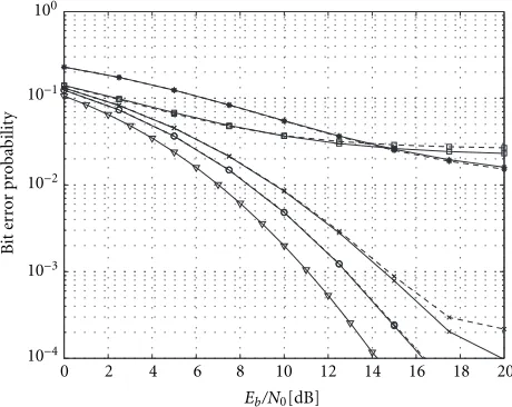
BEPs given by (29) and (31) were evaluated for 8 users employing a spreading factor of 16 and equal transmission powers in the vehicular A channel. The length of zero-forcing and LMMSE equalizers was set to 98 taps (49 chips), and the observation window of the received signal was 80 chips. BEPs are presented in Figure 4 for the conventional Rake receiver, as well as for the ZF and LMMSE chip-level equalizersWL and ˜WLgiven by (7) and (11), respectively. Also the theo-retical single-user bound [49] for the considered channel is given in the figure.
From the results in Figure 4 it can be immediately noted that the Gaussian approximation for BEP gives a good match with the BEP values obtained with (29). Also it is easily seen that asEb/N0increases, the BEP of the Rake receiver saturates due to the MAI. The LMMSE equalizers show a significant BEP improvement when compared to conventional Rake
9Correlation with a spreading code is included inw.
10Gray code mapping of symbols to bits is assumed, and the term Q2(·)
0 2 4 6 8 10 12 14 16 18 20 Eb/N0[dB]
10−4
10−3
10−2
10−1
100
B
it
er
ror
pr
obabilit
y
Figure4: BEP versusEb/N0for 8 QPSK users with a spreading
fac-tor of 16 in the Vehicular A channel. BEP (solid line) are presented with Gaussian approximation (dashed line) for Rake receiver (), zero-forcing equalizer (∗), as well as for the LMMSE receivers given by (7) (◦) and by (11) (×). Also the performance bound of channel () is included.
receiver, whereas the ZF equalizer attains the performance of a Rake receiver only at highEb/N0. The performance diff er-ence between ZF and LMMSE chip-level equalizer receivers is caused by the noise enhancement typical to the ZF equal-izers [50]. The performance difference between the LMMSE equalizersWLand ˜WLis relatively small, less than 2 dB at the practicalEb/N0range. Hence, it can be noted that the chang-ing chip correlations do not have a significant effect on the performance of the LMMSE equalizer in a WCDMA down-link. However, the LMMSE equalizer defined by (11) shows moderate saturation in performance at highEb/N0values.
In Figure 5, the sample distribution functions are pre-sented for the SINRγwith the Rake receiver, the ZF equalizer and LMMSE equalizers. The sample distribution functions are given forES/N0values of 6 dB and 18 dB. The SINR for a zero-forcing equalizer presents a strongly skewed sample dis-tribution function with a heavily weighted lower tail. Com-parison of Figures 4 and 5 reveals that the BEP performance is dominated by the lower tail characteristics of an SINR dis-tribution, as expected. AtEb/N0=15 dB, the BEP of the ZF equalizer is close to that of the Rake receiver. At the corre-spondingES/N0(18 dB), the median SINR of the ZF equal-izer is closer to the median SINR of ˜WL, whereas the 10th percentiles11 of SINR are almost equal for the ZF equalizer and Rake receiver. From Figure 5 we can also notice that with increasingES/N0the variance of SINR increases significantly more for the Rake receiver than for LMMSE equalizers. Thus LMMSE equalizers provide a more stable SINR performance than the Rake receiver, which is an important advantage for radio resource management processes.
1110th percentile of a sample set is such a valuexthat at least 10% of
samples are smaller than or equal tox.
−10 −5 0 5 10 15 20 25
Signal to interefence-and-noise ratio (SINR)[dB] 0
0.1 0.2 0.3 0.4 0.5 0.6 0.7 0.8 0.9 1
Sample
dist
ribution
function
Figure 5: Sample distribution functions of SINR are presented
at 6 dB (dashed line) and 18 dB (solid line) signal-to-noise ratios for Rake receiver (), zero-forcing equalizer (∗), as well as for the LMMSE receivers given by (7) (◦) and by (11) (×).
In Figure 6, the average and the 10th percentile of SINR are presented with respect toES/N0. As we could expect from Figure 5, the average SINR is not an adequate figure of merit. According to average SINR, the performance of the ZF equal-izer approaches the performance of LMMSE equalequal-izers with high ES/N0. However, the 10th percentile of SINR appears to be able to capture several performance characteristics. It shows that the performance of the Rake receiver saturates after ES/N0 = 13 dB (Eb/N0 = 10 dB), and that the per-formances of the ZF equalizer and Rake receiver cross at
ES/N0 = 18 dB. It also shows that the performance of the LMMSE equalizer ˜WLstarts to saturate atES/N0=23 dB.
The ratio of symbol energyEs to the total powerPT of base station signal was varied by scaling the powers of in-terfering users. The ratioEs/PT describes the load of a base station, with low Es/PT values indicating a heavily loaded system. At the same time, theEs/N0 values that maintained the 10th percentile of SINR at a predefined target value were searched. The target values were set to−3 dB and 0 dB, which resulted in all cases 13–15% and 6–8% BEPs, respectively. The results are presented in Figure 7. The horizontal diff er-ences between the curves indicate how much the transmis-sion powers of interfering users can be increased while main-taining the desired user’s transmission power constant. The amount that the desired user’s transmission power can be de-creased while maintaining the transmission powers of inter-fering users at a constant level is also indicated by the diff er-ences between the curves, as depicted in the figure.
5.2. Bit error rate simulations
0 5 10 15 20 25 Signal to noise ratio [dB]
−15
Figure6: Average (a) and 10th percentile (b) of SINR versus
signal-to-noise ratio are presented for Rake receiver (), zero-forcing equalizer (∗), as well as for the LMMSE receivers given by (7) (◦) and by (11) (×).
Doppler frequency shift at the 2 GHz carrier frequency. A spreading factor of 64 was used on the common pilot chan-nel, and the power of the pilot channel was scaled to 10% of the total transmitted power PT. Filter lengths of 19 taps were used with the equalizers, except for the 16-tap CPICH trained equalizer.
BERs for differentEb/N0values are presented in Figure 8 for the considered adaptive receivers, excluding the CPICH trained equalizer. Also the performance of the LMMSE equalizer ˜WLand the theoretical single-user bound [49] for the considered channel are included in the figure. In Figure 8, all receivers had a perfect knowledge of the channel. The per-formance of the Rake receiver is degraded by MAI even at low
−3 −2 −1 0 1 2 3 4 5 6
line) and 0 dB (dashed line) target values of 10th percentile of SINR with Rake receiver () and LMMSE receivers given by (7) (◦) and by (11) (×).
Prefilter-Rake with Griffiths Prefilter-Rake with HRLS
Figure 8: Bit error rates versusEb/N0 for 4QPSK users
(spread-ing factor 8) and common pilot channel (spread(spread-ing factor 64) with known channel response in Channel II.
0 2 4 6 8 10 12 14 16 18 20 Eb/N0(dB)
10−3
10−2
10−1
100
Bi
t
er
ror
ra
te
Rake receiver
CPICH-trained equalizer Griffiths equalizer CR-MOE equalizer
Prefilter-Rake with Griffiths Prefilter-Rake with HRLS Prefilter-Rake with Levinson
LMMSE
Perfor
manc
e bound
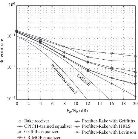
Figure9: Bit error rates versusEb/N0 for 4 QPSK users
(spread-ing factor 8) and common pilot channel (spread(spread-ing factor 64) with estimated channel response in Channel II.
−2 0 2 4 6 8 10 12 14
Es/PT(dB)
10−3
10−2
10−1
Bi
t
er
ror
ra
te
Rake receiver
CPICH-trained equalizer Griffiths equalizer CR-MOE equalizer
Prefilter-Rake with Griffiths Prefilter-Rake with HRLS Prefilter-Rake with Levinson LMMSE
Figure10: Bit error rates versusEs/PT atEb/N0 =12 dB (Es/N0 =
15 dB) with estimated channel response in Channel II.
Figure 10 with respect to the ratio of the desired user’s sym-bol energy Es to the total transmitted powerPT. Different Es/PTvalues were obtained by simulating different numbers of equal power users employing a spreading factor 64.
Comparing Figures 8 and 9, it can be noted that the
per-formance of a CR-MOE equalizer is affected by channel es-timation errors. However, the performance degradation due to channel estimation is not severe. It is slightly surprising to see that the prefilter-Rake and Rake receivers are not sig-nificantly affected by channel estimation. This indicates that their performances are limited by other factors, like MAI in the case of the Rake receiver.
From the results it can be seen that both prefilter-Rake receivers as well as CR-MOE and Griffiths’ equaliz-ers provide performance improvements when compared to the conventional Rake receiver. The performance gain also increases with increasing Eb/N0 (Figure 9) and decreasing
Es/PT (Figure 10), that is, when MAI becomes more domi-nant. However, at highEs/PT values (low number of users) the Rake receiver provides equal or better performance than the CR-MOE or Griffiths’ equalizer. From Figure 10 it can be noted that with decreasing numbers of users and, thus, MAI, the performance of prefilter-Rake and Rake receivers approach the performance of the LMMSE receiver.
The CPICH trained equalizer provides performance im-provement over the Rake receiver at a relatively highEb/N0 range (Figure 9) or in severe MAI situations (Figure 10). The CPICH trained equalizer suffers from insufficient adaptation caused by low SNR in the adaptation. The SNR is especially low at highEs/PT values, indicating low CPICH power. At the same range also the BER of the equalizer saturates as seen in Figure 10.
6. CONCLUSIONS
One approach to improve the performance of WCDMA downlink receivers was studied in this paper, namely, channel equalization prior to despreading. The presented receivers, consisting of a channel equalizer, a correlator, and a decision device, restore to some extent the orthogonality of users, and, thus, suppress MAI when orthogonal spreading sequences are employed.
The zero-forcing and LMMSE solutions for chip-level channel equalizers were defined and the effects of WCDMA downlink signal structure to the equalizers were addressed. The performance of chip-level channel equalizers was stud-ied with respect to bit error probability and signal-to-interference-plus-noise ratio in a frequency-selective fading channel.
ACKNOWLEDGMENTS
The research at the University of Oulu has been supported by the Academy of Finland, Nokia, and Texas Instruments.
REFERENCES
[1] H. Holma and A. Toskala, Eds.,Wideband CDMA for UMTS, John Wiley and Sons, New York, NY, USA, 2000.
[2] S. Verd ´u, Multiuser Detection, Cambridge University Press, Cambridge, UK, 1998.
[3] P. B. Rapajic and B. S. Vucetic, “Adaptive receiver structures for asynchronous CDMA systems,” IEEE Journal on Selected Areas in Communications, vol. 12, no. 4, pp. 685–697, 1994. [4] U. Madhow and M. L. Honig, “MMSE interference
sup-pression for direct-sequence spread-spectrum CDMA,”IEEE Trans. Communications, vol. 42, no. 12, pp. 3178–3188, 1994. [5] A. Klein, Multi-user detection of CDMA signals—algorithms and their application to cellular mobile radio, Ph.D. thesis, Uni-versity of Kaiserslautern, Kaiserslautern, Germany, 1996. [6] A. Klein, “Data detection algorithms specially designed for
the downlink of CDMA mobile radio systems,” inProc. IEEE Vehicular Tech. Conf., vol. 1, pp. 203–207, Phoenix, Ariz, USA, May 1997.
[7] C. D. Frank and E. Visotsky, “Adaptive interference suppres-sion for direct-sequence CDMA systems with long spread-ing codes,” inProc. 36th Annual Allerton Conf. on Commun., Control, and Computing, pp. 411–420, Monticello, Ill, USA, September 1998.
[8] I. Ghauri and D. T. M. Slock, “Linear receivers for the DS-CDMA downlink exploiting orthogonality of spreading se-quences,” inProc. 32nd Asilomar Conf. on Signals, Systems, and Computers, vol. 1, pp. 650–654, Asilomar, Calif, USA, Novem-ber 1998.
[9] K. Hooli, M. Latva-aho, and M. Juntti, “Multiple access inter-ference suppression with linear chip equalizers in WCDMA downlink receivers,” inProc. IEEE Global Telecommunications Conf., vol. 1, pp. 467–471, Rio de Janeiro, Brazil, December 1999.
[10] M. Juntti and K. Hooli, “Overview on linear multiuser equal-izers for DS-CDMA systems,” in Wireless Communication Technologies: New Multimedia Systems, R. Kohno, N. Mori-naga, and S. Sampei, Eds., chapter 5, pp. 97–129, Kluwer Aca-demic, 2000.
[11] M. Bossert and T. Frey, “Interference cancellation in the synchronous downlink of CDMA systems,” in Cost 231 TD(94)70, Prag, Czech, April 1994.
[12] T. Krauss and M. Zoltowski, “MMSE equalization under con-ditions of soft hand-off,” inProc. IEEE Int. Symp. Spread Spec-trum Techniques and Applications, vol. 2, pp. 540–544, Parsip-pany, NJ, USA, September 2000.
[13] T. Krauss and M. Zoltowski, “Chip-level MMSE equaliza-tion at the edge of the cell,” inProc. IEEE Wireless Commun. and Networking Conf., vol. 1, pp. 386–392, Chicago, Ill, USA, September 2000.
[14] C. D. Frank, “MMSE reception of DS-CDMA with open-loop transmit diversity,” inProc. IEE Int. Conf. 3G Mobile Commun. Tech., London, UK, March 2001.
[15] M. Lenardi, A. Medles, and D. Slock, “Comparison of down-link transmit diversity schemes for RAKE and SINR maximiz-ing receivers,” inProc. IEEE Int. Conf. Commun., Helsinki, Finland, June 2001.
[16] P. Darwood, P. Alexander, and I. Oppermann, “LMMSE chip equalisation for 3GPP WCDMA downlink receivers with channel coding,” inProc. IEEE Int. Conf. Commun., Helsinki, Finland, June 2001.
[17] H. Elders-Boll, “Performance of an adaptive LMMSE chip equalizer for UTRA-FDD downlink detection,” in Proc. COST 262 Workshop, pp. 1–6, Ulm, Germany, January 2001.
[18] M. Heikkil¨a, “A novel blind adaptive algorithm for chan-nel equalization in WCDMA downlink,” in Proc. IEEE Int. Symp. Pers., Indoor, Mobile Radio Commun., San Diego, Calif, USA, 30 September–3 October 2001.
[19] P. M. Grant, S. M. Spangenberg, D. G. M. Cruickshank, S. McLaughlin, and B. Mulgrew, “New adaptive multiuser de-tection technique for CDMA mobile receivers,” inProc. IEEE Int. Symp. Pers., Indoor, Mobile Radio Commun., vol. 1, pp. 52–54, Osaka, Japan, September 1999.
[20] S. Werner and J. Lilleberg, “Downlink channel decorrelation in CDMA systems with long codes,” inProc. IEEE Vehicular Tech. Conf., vol. 2, pp. 1614–1617, Houston, Tex, USA, July 1999.
[21] K. Li and H. Liu, “A new blind receiver for downlink DS-CDMA communications,”IEEE Communications Letters, vol. 3, no. 7, pp. 193–195, 1999.
[22] P. Komulainen and M. Heikkil¨a, “Adaptive channel equal-ization based on chip separation for CDMA downlink,” in Proc. IEEE Int. Symp. Pers., Indoor, Mobile Radio Commun., vol. 3, pp. 1114–1118, Osaka, Japan, September 1999. [23] M. Heikkil¨a, P. Komulainen, and J. Lilleberg, “Interference
suppression in CDMA downlink through adaptive channel equalization,” inProc. IEEE Vehicular Tech. Conf., vol. 2, pp. 978–982, Amsterdam, The Netherlands, September 1999. [24] P. Komulainen, M. Heikkil¨a, and J. Lilleberg, “Adaptive
channel equalization and interference suppression for CDMA downlink,” inProc. IEEE Int. Symp. Spread Spectrum Tech-niques and Applications, vol. 2, pp. 363–367, Parsippany, NJ, USA, September 2000.
[25] S. Werner, M. L. R. de Campos, and J. A. Apolinario, “Kalman-filter based chip estimator for WCDMA downlink detection,” inProc. European Signal Processing Conf., Tam-pere, Finland, September 2000.
[26] K. Hooli, M. Latva-aho, and M. Juntti, “Novel adaptive chan-nel equalizer for WCDMA downlink,” inProc. COST 262 Workshop, pp. 7–11, Ulm, Germany, January 2001.
[27] K. Hooli, M. Latva-aho, and M. Juntti, “Performance eval-uation of adaptive chip-level channel equalizers in WCDMA downlink,” inProc. IEEE Int. Conf. Commun., vol. 6, pp. 1974– 1979, Helsinki, Finland, June 2001.
[28] G. Bottomley, T. Ottoson, and Y.-P. E. Wang, “A generalized RAKE receiver for interference suppression,”IEEE Journal on Selected Areas in Communications, vol. 18, no. 8, pp. 1536– 1545, 2000.
[29] D. Dahlhaus and A. Jarosch, “Comparison of conventional and adaptive receiver concepts for the UTRA downlink,” in Proc. Universal Mobile Telecommunications System (UMTS) Workshop, pp. 233–242, Reisensburg, Germany, November 1998.
[30] S. Qureshi, “Adaptive equalization,” Proceedings of the IEEE, vol. 73, no. 9, pp. 1349–1387, 1985.
[32] S. M. Kay, Fundamentals of Statistical Signal Processing: Es-timation Theory, Prentice-Hall, Englewood Cliffs, NJ, USA, 1993.
[33] K. Hooli, M. Latva-aho, and M. Juntti, “Comparison of LMMSE receivers in DS-CDMA downlink,” inProc. ACTS Mobile Communication Summit, vol. 2, pp. 649–654, Sorrento, Italy, June 1999.
[34] T. Krauss, W. Hillery, and M. Zoltowski, “MMSE equaliza-tion for forward link in 3G CDMA: Symbol-level versus chip-level,” inProc. 10th IEEE Workshop on Statistical Signal and Array Processing, pp. 18–22, Pocono Manor, Pa, USA, August 2000.
[35] H. Liu,Signal Processing Applications in CDMA Communica-tions, Artech House, Norwood, Mass, USA, 2000.
[36] D. Slock and I. Ghauri, “Blind maximum SINR receiver for the DS-CDMA downlink,” inProc. IEEE Int. Conf. Acoustics, Speech, Signal Processing, pp. 2485–2488, Istanbul, Turkey, June 2000.
[37] S. Mudulodu and A. Paulraj, “A blind multiuser receiver for the CDMA downlink,” inProc. IEEE Int. Conf. Acoustics, Speech, Signal Processing, pp. 2933–2936, Istanbul, Turkey, June 2000.
[38] S. Chowdhury, M. D. Zoltowski, and J. S. Goldstein, “Reduced-rank adaptive MMSE equalization for high-speed CDMA forward link with sparse multipath channels,” inConf. Record of the 34th Asilomar IEEE Conf. on Signals, Systems, and Computers, pp. 965–969, Pacific Grove, Calif, USA, 29 October–1 November 2000.
[39] F. Petre, M. Moonen, M. Engels, B. Gyselinckx, and H. De Man, “Pilot-aided adaptive chip equalizer receiver for interef-erence suppression in DS-CDMA forward link,” inProc. IEEE Vehicular Tech. Conf., vol. 1, pp. 303–308, Boston, Mass, USA, September 2000.
[40] J. R. Treichler, C. R. Johnson, and M. G. Larimore,Theory and Design of Adaptive Filters, John Wiley and Sons, New York, NY, USA, 1987.
[41] S. Haykin, Adaptive Filter Theory, Prentice-Hall, Upper Sad-dle River, NJ, USA, 3rd edition, 1996.
[42] M. Honig, U. Madhow, and S. Verd ´u, “Blind adaptive mul-tiuser detection,” IEEE Transactions on Information Theory, vol. 41, no. 3, pp. 944–960, 1995.
[43] L. Mailaender, “Low-complexity implementation of CDMA downlink equalization,” inProc. IEE Int. Conf. 3G Mobile Commun. Tech., London, UK, March 2001.
[44] A. Rontogiannis and S. Theodoridis, “An adaptive LS algo-rithm based on orthogonal Householder transformations,” in Proc. IEEE Int. Conf. on Electronics, Circuits, and Systems, pp. 860–863, 1996.
[45] T. K. Moon and W. C. Stirling, Mathematical Methods and Algorithms for Signal Processing, Prentice-Hall, Upper Saddle River, NJ, USA, 2000.
[46] G. H. Golub and C. F. Van Loan, Matrix Computations, The Johns Hopkins University Press, Baltimore, Md, USA, 2nd edition, 1989.
[47] ETSI, “Selection procedures for the choice of radio trans-mission technologies of the universal mobile telecommuni-cations systems (UMTS),” Tech. Rep. version 3.0.0, European Telecommunications Standards Institute (ETSI), May 1997. [48] M. J. Juntti and M. Latva-aho, “Bit error probability analysis
of linear receivers for CDMA systems in frequency-selective fading channels,” IEEE Trans. Communications, vol. 47, no. 12, pp. 1788–1791, 1999.
[49] M. K. Simon and M.-S. Alouini, “A unified approach to the performance analysis of digital communication over general-ized fading channels,” Proceedings of the IEEE, vol. 86, no. 9, pp. 1860–1877, 1985.
[50] J. G. Proakis, Digital Communications, McGraw-Hill, New York, NY, USA, 3rd edition, 1995.
Kari Hooli received his M.S. degree in electrical engineering from the University of Oulu, Finland in 1998. Since 1998, he has been a Research Scientist at Centre for Wireless Communications, University of Oulu. Currently, he is pursuing Dr.Tech. de-gree in electronic engineering with reseach interests in statistical signal processing, in-terference suppression, and CDMA systems.
Markku Juntti was born in Kemi, Fin-land, in 1969. He received his M.S. (Tech.) and Dr.Tech. degrees in electrical engineer-ing from University of Oulu, Oulu, Fin-land in 1993 and 1997, respectively. Dr. Juntti has been a Research Scientist and Research Project Manager at Telecommu-nication Laboratory and Centre for Wire-less Communications, University of Oulu in 1992–1997. In academic year 1994–1995 he
was a Visiting Research Scientist at Rice University, Houston, Tex. In 1998 he was an Acting Professor at the University of Oulu. In 1999–2000 he was with Nokia Networks, Radio Access Systems in Oulu as a Senior Specialist of W-CDMA Research and Solutions. Dr. Juntti has been a Professor of Telecommunications at University of Oulu since 2000. He is also Research Manager of UMTS Research at Centre for Wireless Communications, University of Oulu. Dr. Juntti consults the telecommunication industry, for example, by training its personnel. Dr. Juntti’s research interests include com-munication theory and signal processing for wireless communica-tion systems as well as their applicacommunica-tion in wireless communicacommunica-tion system design. He is an author in book “W-CDMA for UMTS” published by Wiley. Dr. Juntti is a member of IEEE. He was Sec-retary of IEEE Communication Society Finland Chapter in 1996– 1997 and the Chairman for years 2000–2001. He has been Secretary of the Technical Program Committee of the 2001 IEEE Interna-tional Conference on Communications (ICC ’01), and Chairman of the Technical Program Committees of 1999 Finnish Signal Pro-cessing Symposium (FINSIG ’99) and the 2000 Finnish Wireless Communications Workshop (FWCW ’00).
Markku J. Heikkil¨areceived his M.S. degree in electrical engineering from the University of Oulu, Oulu, Finland, in 1997. He is cur-rently a Senior Research Engineer in Nokia, Research and Technology Access, Finland. From 1996 to 1997, he was employed as a Research Assistant at the Telecommunica-tion Laboratory of the University of Oulu. Since 1997, he has been with Nokia, Fin-land. His research interests include
Petri Komulainenwas born in Kiuruvesi, Finland, in 1971. He received the M.S. (Dipl. Eng.) degree in 1996 from the pro-gramme of Information Engineering of the University of Oulu, Finland, with a thesis on turbo codes. In 1997, he worked as a Visiting Research Scholar at the New Jer-sey Institute of Technology (NJIT), Newark. Since then he has worked for Nokia Mobile Phones in Oulu, Finland, specialising in the
research and development of various WCDMA terminal receiver algorithms.
Matti Latva-ahoreceived the M.S. in elec-trical engineering, Lic.Tech., and Dr.Tech. degrees from the University of Oulu, Fin-land in 1992, 1996, and 1998, respectively. From 1992 to 1993, he was a Research En-gineer at Nokia Mobile Phones, Oulu, Fin-land. During the years 1994–1998 he was a Research Scientist at Telecommunication Laboratory and Centre for Wireless Com-munications at the University of Oulu.
Cur-rently, Professor Latva-aho is Director of Centre for Wireless Com-munications at the University of Oulu. His research interests in-clude future broadband wireless communication systems and re-lated transceiver algorithms. Professor Latva-aho has published more than 50 conference or journal papers in the field of CDMA communications.
Jorma Lilleberg was born in Rovaniemi, Finland, in 1953. He received the Diploma Engineer and Licentiate of Technology de-grees in electrical engineering at the Uni-versity of Oulu, Oulu, Finland in 1979 and 1984, respectively and the Doctor of Tech-nology degree at the Tampere University of Technology, Tampere, Finland in 1992. From 1992 to 1993 he worked at the Tech-nical Research Center of Finland, in Oulu,