Pilot-Symbol-Assisted Channel Estimation
for Space-Time Coded OFDM Systems
King F. Lee
Multimedia Architecture Lab, Motorola Labs, Schaumburg, IL 60196, USA Email: [email protected]
Douglas B. Williams
School of Electrical and Computer Engineering, Georgia Institute of Technology, Atlanta, GA 30332, USA Email: [email protected]
Received 31 May 2001 and in revised form 5 March 2002
Space-time coded orthogonal frequency division multiplexing (OFDM) transmitter diversity techniques have been shown to pro-vide an efficient means of achieving near optimal diversity gain in frequency-selective fading channels. For these systems, knowl-edge of the channel parameters is required at the receivers for diversity combining and decoding. In this paper, we propose a low complexity, bandwidth efficient, pilot-symbol-assisted (PSA) channel estimator for multiple transmitter OFDM systems. The pilot symbols are constructed to be nonoverlapping in frequency to allow simultaneous sounding of the multiple channels. The time-varying channel responses are tracked by interpolating a set of estimates obtained through periodically transmitted pilot symbols. Simulations are used to verify the effectiveness of the proposed estimator and to examine its limitations. It is also shown that the PSA channel estimator has a lower computational complexity and better performance than a previously proposed decision-directed minimum mean square error MMSE channel estimator for OFDM transmitter diversity systems.
Keywords and phrases:transmitter diversity, OFDM, channel estimation, pilot symbols, interpolation.
1. INTRODUCTION
The mobile wireless channel suffers from multipath fading that severely attenuates the received signal during periods of deep fades. Spatial diversity is a well-known technique for improving the performance and reliability of wireless com-munications over fading channels. Traditionally, spatial di-versity has been implemented at the receiver end by using multiple antennas at the receiver and then combining sig-nals to improve the quality of the received signal. Unfortu-nately, receiver diversity requires multiple, widely-spaced an-tennas and multiple radio frequency (RF) front-end circuits at the receiver. This multiplicity of receiver front-end hard-ware is undesirable and impractical for portable receivers, such as pagers or cellular handsets, where physical size and current drain are important constraints. Transmitter diver-sity, on the other hand, can be implemented with multiple spatially separated antennas at the transmitter and requires only a single antenna and front-end circuit at the receiver. Transmitter diversity techniques are, therefore, very suitable for paging, cellular, and portable wireless data services, where a small number of base stations serve a large number of mobile users and where spatially separated antennas can be easily implemented at the base stations. Hence, transmitter
diversity has received strong interest in recent years, es-pecially in the mobile communications research commu-nity. Furthermore, the channels over which these high data rate mobile communications systems operate are generally frequency-selective, so transmitter diversity techniques that are effective in frequency-selective fading channels are of spe-cial interest.
X(u) Serial to parallel
X(n) Transmitter diversity encoder
X1(n)
IDFT & cyclic prefix
Tx1
h1(n)
X2(n)
IDFT & cyclic prefix
Tx2
h2(n)
Rx
ˆ
X(u) Parallel to serial
ˆ
X(n) Diversity
decoder Y(n)
Prefix removal
& DFT
r(n)
ˆ
Λ1(n) ˆ
Λ2(n) estimatorChannel
Figure1: Block diagram of a two-branch OFDM transmitter diversity system.
was proposed. The primary shortcoming of the MMSE chan-nel estimation approach is the high computational complex-ity required to update the channel estimates during the data transmission mode. In this paper, we investigate a low com-plexity channel estimation technique for multiple transmit-ter OFDM systems. The proposed technique uses bandwidth efficient pilot symbols to facilitate temporal estimation of the multiple channel responses. Simple interpolation filters are then used to update the estimates during the data transmis-sion mode.
2. OFDM TRANSMITTER DIVERSITY SYSTEMS
A block diagram of a general two-branch OFDM transmitter diversity system is shown in Figure 1. LetX(u) denote the in-put serial data symbols with symbol durationTS. The serial to parallel converter collectsKserial data symbols into a data vectorX(n) =[X(n,0) X(n,1)· · ·X(n, K−1)]T,which has a block duration ofKTS.1The transmitter diversity encoder
codesX(n) into two vectorsX1(n) andX2(n) according to an
appropriate coding scheme as in [1, 2, 3, 4]. The coded vec-torX1(n) is modulated by an inverse discrete Fourier
trans-form (IDFT) into an OFDM symbol sequence. A lengthG cyclic extension is added to the OFDM symbol sequence, and the resulting signal is transmitted from the first trans-mit antenna. Similarly, the vectorX2(n) is modulated by an
IDFT, cyclically extended, and transmitted from the second transmit antenna. Leth1(n) denote the impulse response of
the channel between the first transmit antenna and the re-ceiver andh2(n) denote the impulse response of the channel
between the second transmit antenna and the receiver. The length of the cyclic extension is chosen to be greater than
1Throughout the paper we use the notation thatA(n, k) is thekth ele-ment of the vectorA(n).
or equal to L, the order of the channel impulse responses, that is,G≥L. At the receiver, the received signal vector first has the cyclic prefix removed and is then demodulated by a discrete Fourier transform (DFT) to yield the demodulated signal vector Y(n). Assuming that the channel impulse re-sponses remain constant during the entire block interval, it can be easily shown that the demodulated signal is given by
Y(n)=Λ1(n)X1(n) +Λ2(n)X2(n) +Z(n), (1)
whereΛ1(n) andΛ2(n) are two diagonal matrices whose
el-ements are the DFTs of the respective channel impulse re-sponses,h1(n) andh2(n), andZ(n) is the DFT of the channel
noise. Elements of Z(n) are generally assumed to be addi-tive white Gaussian noise with varianceσ2
Z. Clearly, the
de-modulated signal vectorY(n) is the superposition of the two encoded vectors X1(n) andX2(n), which makes estimation
of the channel parameters (i.e.,h1(n) andh2(n) or,
equiva-lently,Λ1(n) andΛ2(n)) fromY(n) challenging for
transmit-ter diversity systems, especially during the data transmission mode.
3. CHANNEL ESTIMATION FOR OFDM TRANSMITTER DIVERSITY SYSTEMS
even with decision-directed channel estimation, known sym-bols2 are periodically transmitted to avoid excessive error
propagation. The channel estimator in [12] is essentially a decision-directed channel estimator where the decoded data symbols are used, during the data transmission mode, to esti-mate the set of channel parameters that minimizes the mean-square error (MSE) cost function
K−1
k=0
Y(n, k)−
M
m=1
Λm(n, k)Xm(n, k)
2
, (2)
whereMis the number of transmitters. With PSA channel es-timation, known pilot symbols are inserted into the transmit symbol stream, usually at a regular interval. At the receiver, the pilot symbols are extracted to provide a temporal esti-mate of the channel parameters at the pilot instants. These temporal estimates are then either filtered or interpolated to provide estimates of the channel parameters during the data transmission mode.
It is interesting to note that although both the decision-directed channel estimator and the PSA channel estimator estimate the channel parameters using known symbols in the form of training and pilot symbols, there is a major diff er-ence between the two estimators during the data transmis-sion mode. With the decitransmis-sion-directed approach, decoded symbols are used to update the channel estimates contin-uously during the data transmission mode. On the other hand, with the PSA approach, decoded symbols during the data transmission mode are not used to determine the chan-nel. Channel estimates are generated either by filtering or interpolating the temporal estimates obtained at the pilot instants. This difference has special significance for trans-mitter diversity systems where the multiple transmitted sig-nals tend to interfere with the channel estimation process. During the training or pilot mode, the interferences among the multiple transmitted signals can be easily minimized for the decision-directed channel estimator or PSA channel es-timator by employing properly designed orthogonal train-ing symbols [12, 13] or pilot symbols. However, there is no such “luxury” during the data transmission mode, because the multiple transmitted signals typically correspond to ran-domly distributed data symbols. Hence, the MMSE solution for finding the “best” estimate amid the interfering signals, such as in [12], is indeed the logical approach for decision-directed channel estimation for transmitter diversity systems. For the PSA channel estimator, however, the main challenges are in minimizing the interferences among the pilot sym-bols from the multiple transmitters and in the design of the interpolator. The interferences during the data transmission mode, which are more difficult to resolve, are not a concern at all for PSA channel estimators. Consequently, PSA channel estimation will be shown to be the better choice for transmit-ter diversity systems.
2To avoid possible confusion with PSA channel estimation approaches, these known symbols for decision-directed channel estimation are some-times referred to as training symbols.
3.1. Pilot symbols for multiple transmitter OFDM systems
Pilot-symbol-assisted (PSA) channel estimation techniques for single transmitter systems have been proposed and are well understood [14, 15]. However, there is little literature on PSA channel estimation techniques for multiple trans-mitter systems. In [16], an alternating PSA channel estima-tion scheme was suggested for multiple transmitter systems. To estimate the channel from themth transmitter to the re-ceiver, the pilot symbols are transmitted only from themth transmitter, while all the other transmitters either transmit null symbols or stop transmission. With this alternating pilot symbol scheme,Mtimes as many pilot symbols are needed to estimate all the channels in anMtransmit antenna system as compared to that required for a single transmit antenna system. The expansion in pilot symbols is undesirable from the standpoint of data throughput and bandwidth efficiency. Here, we propose a multirate PSA channel estimation tech-nique that does not require expansion in the number of pilot symbols for multiple transmitter OFDM systems.
Although the different signals from multiple transmitters in a transmitter diversity system tend to interfere with each other, pilot symbols can be constructed for multiple trans-mitter OFDM systems to avoid this form of interference and, thus, simplify the task of channel estimation during the pilot mode. Notice in (1) that, for properly designed OFDM trans-mitter diversity systems, the subchannels for the signal from each transmitter are decoupled, that is,Λ1(n) andΛ2(n) are
diagonal matrices. Therefore, if the pilot symbols are con-structed so that pilot symbols transmitted from different transmitters occupy different frequency bins, any individual symbol in the demodulated signal vectorY(n) will then con-tain a contribution from only one transmitter, and the com-plex channel gain for that particular subcarrier can be eas-ily estimated. An obvious choice is to have the pilot symbols among the transmitters evenly distributed while nonoverlap-ping in frequency. In theory, any pilot symbols that satisfy the nonoverlapping conditions will be sufficient. In practice, the pilot symbols should be chosen to have other desirable OFDM properties as well. Chirp sequences are attractive for channel estimation in OFDM systems because they have a flat power spectrum and a low peak-to-average power ratio [17]. Here, we propose the use of chirp sequences, with different phase offsets from antenna to antenna, as pilot symbols for multiple transmitter OFDM systems. Define a lengthKchirp sequence as
C(k)=ejπk2/K
, 0≤k≤K−1. (3)
LetPSm(n, k) denote thekth tone of the pilot symbol trans-mitted from themth transmit antenna during the block in-stantn. The pilot symbols are constructed as
PSm(n, k+m−1)
=
(−1)m√MC(k+m−1), if (k)M=0,
0, otherwise,
k=0
Data symbol Pilot symbol Null symbol
Legend: D P
Figure2: Pilot symbol patterns for an example OFDM transmitter diversity system withK=8 andM=2.
whereMis the number of transmitters, (k)Mdenotesk mod-uloM, 1≤m≤M, 0≤k≤K−1, and 1≤m+k≤K. Figure 2 shows the pilot symbol patterns for an example two-branch OFDM transmitter diversity system.
Since the pilot symbols are known to the receiver and, during the pilot instants, each symbol inY(n) contains only the contribution from one transmitter, the least-square esti-mate3for the (k+m−1)th diagonal element ofΛ
m(n), that
is, the complex gain of the (k+m−1)th subcarrier from the mtransmitter, is given by
˜
Notice that the nonzero estimate
˜
Λm(n, k+m−1)=Λm(n, k+m−1) +W(n, k+m−1), (6)
whereΛm(n, k+m−1) is the actual complex gain of the (k+ m−1)th subcarrier from themth transmitter andW(n, k+ m−1) is a zero-mean complex Gaussian random variable with varianceσ2
W =σZ2/M.
3For OFDM systems with fully decoupled subchannels, the least-square channel estimator is equivalent to the zero-forcing channel estimator [5].
A number of two-dimensional (2D) filtering techniques have been proposed for PSA channel estimation for OFDM systems. The 2D Wiener filter proposed in [6, 7] has fairly high complexity and requires knowledge of the channel statistics. In [11], a robust MMSE interpolator that does not require knowledge of channel statistics was proposed. The in-terpolator in [11], however, requires 2D filtering, a 2D DFT, and a 2D IDFT. Here, we consider a robust yet simple inter-polation approach that does not depend on channel statis-tics and requires only a simple windowing function and one-dimensional interpolation filters.
The diagonal elements of ˜Λm(n) are, in effect, samples of the frequency response of the channel between themth transmitter and the receiver. Leth˜m(n) be the IDFT of the diagonal of ˜Λm(n). In the absence of noise, ˜hm(n) is related to the actual channel impulse response (CIR)hm(n) by [18]
˜
Notice that ˜hm(n) is the sum of circularly shifted images of hm(n). The images in (7) are the direct result of sampling in the frequency domain. To avoid aliasing in the time domain, the conditionK≥M(L+ 1) must be satisfied. To remove the images, ˜hm(n) is passed through a lengthL+ 1 rectangular window of gain M to yield the temporal estimate ˆhm(n) at the pilot instant as
ˆ
where the elements of the noise vectorΞ(n) have a variance ofσ2
WM(L+ 1)/K. SinceM(L+ 1)< K in general, in
addi-tion to removing the images, the windowing operaaddi-tion also reduces the variance of the noise by a factor ofM(L+ 1)/K. These temporal estimates at the pilot instants, ˆhm(n), are then passed through an interpolation filter to provide the estimated channel parameters during the data transmission mode.
3.2. Interpolation of channel parameters for multiple transmitter OFDM systems
(FIR) digital filter, and generatesN−1 interpolated CIR sam-ples at the OFDM symbol rate of 1/((K+G)TS). These inter-polated values provide a robust estimate of the CIRs for the diversity decoder during the data transmission mode.
Notice that the multipath fading process is bandlimited to the maximum Doppler shift frequency fD. Therefore, to satisfy the Nyquist criteria, the sampling rate of the chan-nel estimates must satisfy fs>2fD, where the sampling fre-quency fs=1/(N(K+G)TS). The equivalent condition
N < 1
2fD(K+G)TS (10)
gives an upper bound on the pilot symbol spacing. It is well known that the impulse response of the ideal interpolator for bandlimited signals is the sinc function, which has an infi-nite number of coefficients and is, therefore, unrealizable. A number of practical interpolators have been proposed in [14, 19, 20]. As shown in [19], even order interpolation fil-ters, that is, whenQis odd, do not have linear phase. Nonlin-ear phase distortion can cause discontinuities in the envelope of the interpolated signal. Furthermore, linear phase interpo-lation filters have symmetrical coefficients, which can reduce the number of calculations by a factor of 2. Therefore, we will focus on odd order, linear phase interpolation filters.
In general, the interpolation process improves with in-creased sampling rates and with higher order interpolation filters. However, there is no analytical expression for the in-terpolation error of bandlimited signals using these interpo-lators. Therefore, the interpolation errors of a number of in-terpolators were simulated to provide a qualitative measure of how well they may track a frequency-selective fading chan-nel. The interpolation performance criteria used is the MSE between the interpolated and the actual CIR. Assuming that the pilot symbols are transmitted at block instantsn = pN forp=0,1,2, . . ., the interpolation MSE is defined as
ε=N 1
T(N−1)L NT−1
p=0 pN+N−1
n=pN+1 L−1
l=0
hˆ(n, l)−h(n, l)2,
(11)
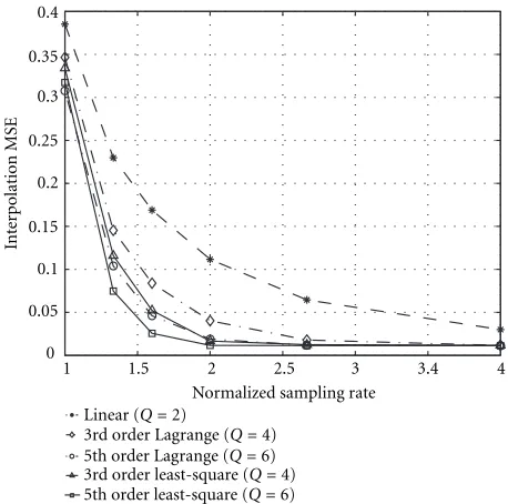
whereNTis the total number of interpolation intervals in the simulation. The interpolation MSEs for an OFDM system withK =128 were simulated at fD =100 Hz with average received signal-to-noise ratio (SNR) of 40 dB and at several pilot symbol spacingsNto measure the effectiveness of the various interpolation filters at different sampling rates. The COST 207 six-ray typical urban channel power delay profile [21] was used throughout the simulations. Simulation results of the interpolation MSE as a function of the normalized sampling rate, fs/(2fD), for the linear interpolator, third and fifth order Lagrange interpolators [19], and third and fifth order least-square interpolators (α=0.5) [20] are shown in Figure 3. Simulation results show that the linear interpolator has significant interpolation error until the sampling rate is well above 4 times the Nyquist rate. As expected, the higher order interpolators all have better performance than the lin-ear interpolator. Although the classical Lagrange interpola-tion filter is optimally flat in the passband, it has a wider
0 0.05 0.1 0.15 0.2 0.25 0.3 0.35 0.4
In
te
rp
olation
M
SE
1 1.5 2 2.5 3 3.4 4
Normalized sampling rate Linear (Q=2)
3rd order Lagrange (Q=4) 5th order Lagrange (Q=6) 3rd order least-square (Q=4) 5th order least-square (Q=6)
Figure3: Interpolation error as a function of the normalized sam-pling rate fs/(2fD).
transition band and has less stopband rejection than other types of “optimum” filters such as the least-square filter [20]. Figure 3 also shows that the least-square filters have a lower interpolation MSE than the Lagrange interpolation filters of the same order. Therefore, the least-square filter is a better choice for interpolating a bandlimited signal. Interestingly, the interpolation errors of the fifth order Lagrange, and the third and fifth order least-square interpolators are very close to the error floor at only twice the Nyquist rate.
Since the insertion of pilot symbols represents a loss of bandwidth efficiency, a main objective in designing PSA channel estimators is to minimize the sampling rate or the number of pilot symbols, that is, to maximize N. Another practical consideration is minimization of the complexity and delay of the interpolator, which usually translates to us-ing the lowest order interpolator possible. From the above simulation results, the third order least-square interpola-tor operating at about twice the Nyquist rate, that is, N ≈ 1/(4fD(K+G)TS), should achieve good interpolation perfor-mance at a reasonable sampling rate, implementation com-plexity, and delay. The hardware complexity of the interpola-tion filter can be further reduced by employing the polyphase filter structure as shown in [20]. A block diagram of the pro-posed PSA channel estimator for a two-branch OFDM trans-mitter diversity system is shown in Figure 4.
3.3. Performance of pilot-symbol-assisted channel estimators
Y(pN,0)
Figure4: Block diagram of the proposed PSA channel estimator for a two-branch OFDM transmitter diversity system.
the STBC-OFDM simulations, the system employed 128 sub-carriers with 4-QAM modulation at a symbol rate of 220
sym-bols per second on each subcarrier, that is,K=128 andTS= 2−20seconds. The pilot symbol spacing was set atN =20 so
that the sampling frequency was near twice the Nyquist rate at a maximum Doppler frequency of 100 Hz. Simulation re-sults of the average bit error rate (BER) performance for a two-branch STBC-OFDM system with ideal channel param-eters and with channel paramparam-eters estimated by a third order Lagrange interpolator are shown in Figure 5. Comparisons to a third order least-square interpolator are shown in Figure 6. Simulation results confirm that at slow fading conditions, such as fD =50 Hz, both the third order Lagrange and third order least-square interpolators perform very well. In fact, for this fading rate there is no noticeable BER degradation between the systems using the ideal channel parameters and those using the estimated parameters from the third order least-square interpolator. AtfD =100 Hz, which corresponds to sampling at about twice the Nyquist rate, the BER perfor-mance with the Lagrange interpolator is degraded slightly, while that with the least-square interpolator still shows very little degradation. This relative performance is in agreement
with the interpolation MSE results in Figure 3, where the third order least-square interpolator has a lower interpola-tion MSE than the third order Lagrange interpolator. At a faster fading condition of fD=150 Hz, which corresponds to sampling at about 1.4 times the Nyquist rate, the BER per-formances of both systems with estimated channel parame-ters are severely degraded as a result of the excessively high interpolation MSE.
For the SFBC-OFDM simulations, the system employed 256 subcarriers with 4-QAM modulation at a symbol rate of 220symbols per second on each subcarrier, that is,K =256
and TS = 2−20 seconds. The pilot symbol spacing was set
10−8 10−6 10−4 10−2 100
0 5 10 15 20 25 30 35 40
Ideal parameters,fD=50 Hz Estimated parameters,fD=50 Hz Ideal parameters,fD=100 Hz Estimated parameters,fD=100 Hz Ideal parameters,fD=150 Hz Estimated parameters,fD=150 Hz
Average received SNR (dB)
A
ver
age
b
it
er
ro
r
rat
e
Figure5: Performance comparison of STBC-OFDM systems with ideal channel parameters and channel parameters estimated by a third order Lagrange interpolator.
10−8 10−6 10−4 10−2 100
0 5 10 15 20 25 30 35 40
Ideal parameters,fD=50 Hz Estimated parameters,fD=50 Hz Ideal parameters,fD=100 Hz Estimated parameters,fD=100 Hz Ideal parameters,fD=150 Hz Estimated parameters,fD=150 Hz
Average received SNR (dB)
A
ver
age
b
it
er
ro
r
rat
e
Figure6: Performance comparison of STBC-OFDM systems with ideal channel parameters and channel parameters estimated by a third order least-square interpolator.
order least-square interpolators have similar performance, and there is only a slight degradation for the systems us-ing the estimated parameters compared to the systems with
10−8 10−6 10−4 10−2 100
0 5 10 15 20 25 30 35 40
Ideal parameters,fD=50 Hz Estimated parameters,fD=50 Hz Ideal parameters,fD=100 Hz Estimated parameters,fD=100 Hz Ideal parameters,fD=150 Hz Estimated parameters,fD=150 Hz
Average received SNR (dB)
A
ver
age
b
it
er
ro
r
rat
e
Figure7: Performance comparison of SFBC-OFDM systems with ideal channel parameters and channel parameters estimated by a third order Lagrange interpolator.
10−8 10−6 10−4 10−2 100
0 5 10 15 20 25 30 35 40
Ideal parameters,fD=50 Hz Estimated parameters,fD=50 Hz Ideal parameters,fD=100 Hz Estimated parameters,fD=100 Hz Ideal parameters,fD=150 Hz Estimated parameters,fD=150 Hz
Average received SNR (dB)
A
ver
age
b
it
er
ro
r
rat
e
Figure8: Performance comparison of SFBC-OFDM systems with ideal channel parameters and channel parameters estimated by a third order least-square interpolator.
better than that of the Lagrange interpolator. At a faster fad-ing condition of fD = 150 Hz, which corresponds to sam-pling at about 1.4 times the Nyquist rate, the BER perfor-mances of both interpolators are severely degraded. Clearly, a sufficient sampling rate is crucial to the performance of the proposed PSA channel estimator. From the above sim-ulation results and the earlier interpolation MSE analysis, a good rule-of-thumb is to set the pilot symbol spacing at about twice the Nyquist rate for the anticipated maximum Doppler frequency.
The simulation results for the SFBC-OFDM are generally similar to that of the STBC-OFDM system shown previously in Figures 5 and 6, where the third order least-square polator slightly outperforms the third order Lagrange inter-polator and both interinter-polators perform reasonably well when the channel fading rate is at or below the anticipated maxi-mum Doppler frequency.
3.4. Comparison with the decision-directed MMSE channel estimator
In this section, the PSA channel estimator proposed in Section 3.2 is briefly compared to the decision-directed MMSE channel estimator of [12].4 As mentioned
previ-ously in Section 3, that decision-directed channel estimator is susceptible to error propagation. Therefore, the perfor-mance of the decision-directed channel estimator depends on the number of errors in the decisions or decoded sym-bols used to direct the channel estimates. To improve the performance of the decision-directed channel estimator, the decoded symbols after error-correction decoding are often used for updating the channel estimation. Hence, the per-formance of the decision-directed channel estimator is af-fected by the performance of the particular error-correction code employed by the system. Here, instead of arbitrarily choosing an error-correction coding scheme, a lower bound for the BER of the decision-directed MMSE channel esti-mator was simulated by using the actual symbols in direct-ing the channel estimation. The simulations used the same STBC-OFDM and SFBC-OFDM system parameters as the systems simulated in Section 3.3. The training symbols in [12] were used for the decision-directed MMSE channel es-timator and the training symbols were sent at the same spac-ing as the pilot symbols for the correspondspac-ing PSA chan-nel estimator. Figure 9 shows the simulation results com-paring the decision-directed MMSE channel estimator with the PSA channel estimator using a third order least-square interpolation filter for the STBC-OFDM system. Figure 10 shows the same comparison for the SFBC-OFDM system. It is interesting to note that, for these particular STBC-OFDM and SFBC-OFDM systems, the PSA channel estimator sig-nificantly outperforms the decision-directed MMSE channel estimator under all fading conditions. These results further
4In [12], a simplified approach was proposed that required identification of the significant taps ofhm(n). Here, we consider only the basic approach for comparison.
10−8 10−6 10−4 10−2 100
0 5 10 15 20 25 30 35 40
MMSE estimator,fD=50 Hz PSA estimator,fD=50 Hz MMSE estimator,fD=100 Hz PSA estimator,fD=100 Hz MMSE estimator,fD=150 Hz PSA estimator,fD=150 Hz
Average received SNR (dB)
A
ver
age
b
it
er
ro
r
rat
e
Figure9: Performance comparison of STBC-OFDM systems with channel parameters estimated by a decision-directed MMSE chan-nel estimator and by the PSA chanchan-nel estimator.
10−8 10−6 10−4 10−2 100
0 5 10 15 20 25 30 35 40
MMSE estimator,fD=50 Hz PSA estimator,fD=50 Hz MMSE estimator,fD=100 Hz PSA estimator,fD=100 Hz MMSE estimator,fD=150 Hz PSA estimator,fD=150 Hz
Average received SNR (dB)
A
ver
age
b
it
er
ro
r
rat
e
Figure10: Performance comparison of SFBC-OFDM systems with channel parameters estimated by a decision-directed MMSE chan-nel estimator and by the PSA chanchan-nel estimator.
support the earlier suggestion that the PSA channel estimator is the better choice for OFDM transmitter diversity systems.
Table1: Computational complexities of the PSA channel estimator and the decision-directed MMSE channel estimator.
Multiplications Additions
PSA channel estimator ((M+M/N)/2)Klog2K+K/N+M(L+ 1)Q (M+M/N)Klog2K+M(L+ 1)(Q−1) MMSE channel estimator∗ ((2M+M2)/2)Klog
2K+MK+ (ML)3/3 (2M+M2)Klog2K+ (ML)3/3
∗AssumingKis a power of two, each FFT requiresK/2log
2Kmultiplications andKlog2Kadditions [22], and Gaussian elimination with an n×nmatrix requiresn3/3 multiplications andn3/3 additions [23].
estimator and the decision-directed MMSE channel estima-tor are shown in Table 1. Compared to the MMSE channel estimator, the PSA channel estimator requires fewer DFTs: M +M/N for the PSA estimator versus 2M +M2 for the
MMSE estimator. Furthermore, calculating the MMSE solu-tion for the decision-directed estimator has a complexity of
ᏻ(M3L3), while the interpolation filter for the PSA
estima-tor has a complexity that is only proportional toML. Clearly, the PSA channel estimator is computationally more efficient than the decision-directed MMSE channel estimator.
4. SUMMARY
A low complexity, bandwidth efficient, pilot-symbol-assisted channel estimator for OFDM transmitter diversity systems has been presented. Different interpolation algorithms have been evaluated and were seen to provide robust channel pa-rameter estimates in various fading environments. Simula-tion results verify that the proposed technique is well suited for channel estimation in space-time coded OFDM trans-mitter diversity systems. It has also been shown that the proposed PSA channel estimator outperforms the decision-directed MMSE channel estimator and is also more compu-tationally efficient.
For ease of presentation, this paper has focused on sys-tems with multiple transmit antennas and a single receive antenna. It should be noted that the proposed approach can also be applied to systems with multiple receive antennas by replicating the proposed channel estimator for each receive antenna.
ACKNOWLEDGMENT
This paper was presented in part at the IEEE International Conference on Acoustics, Speech, and Signal Processing (ICASSP), Salt Lake City, Utah, USA, May 2001.
REFERENCES
[1] D. Agrawal, V. Tarokh, A. Naguib, and N. Seshadri, “Space-time coded OFDM for high data-rate wireless communication over wideband channels,” inProc. IEEE Vehicular Technology Conference, vol. 3, pp. 2232–2236, Ottawa, Ont., Canada, May 1998.
[2] Y. Li, J. C. Chuang, and N. R. Sollenberger, “Transmitter di-versity for OFDM systems and its impact on high-rate data wireless networks,”IEEE Journal on Selected Areas in Commu-nications, vol. 17, no. 87, pp. 1233–1243, 1999.
[3] K. F. Lee and D. B. Williams, “A space-time coded transmitter diversity technique for frequency selective fading channels,” inProc. IEEE Sensor Array and Multichannel Signal Processing Workshop, pp. 149–152, Cambridge, Mass, USA, March 2000. [4] K. F. Lee and D. B. Williams, “A space-frequency transmit-ter diversity technique for OFDM systems,” inProc. IEEE Global Telecommunications Conference, vol. 3, pp. 1473–1477, San Francisco, Calif, USA, November 2000.
[5] J.-J. van de Beek, O. Edfors, M. Sandell, S. K. Wilson, and P. O. B¨orjesson, “On channel estimation in OFDM systems,” in Proc. IEEE Vehicular Technology Conference, vol. 2, pp. 815– 819, Chicago, Ill, USA, July 1995.
[6] P. Hoeher, S. Kaiser, and P. Robertson, “Two-dimensional pilot-symbol-aided channel estimation by wiener filtering,” in Proc. IEEE Int. Conf. Acoustics, Speech, Signal Processing, vol. 3, pp. 1845–1848, Munich, Germany, April 1995.
[7] P. Hoeher, S. Kaiser, and P. Robertson, “Pilot-symbol-aided channel estimation in time and frequency,” inProc. IEEE GLOBECOM Communication Theory Mini-Conference, vol. 3, pp. 90–96, Phoenix, Ariz, USA, November 1997.
[8] O. Edfors, M. Sandell, J.-J. van de Beek, S. K. Wilson, and P. O. B¨orjesson, “OFDM channel estimation by singular value de-composition,”IEEE Trans. Communications, vol. 46, no. 7, pp. 931–939, 1998.
[9] O. Edfors, M. Sandell, J.-J. van de Beek, S. K. Wilson, and P. O. B¨orjesson, “Analysis of DFT-based channel estimators for OFDM,”Wireless Personal Communications, vol. 12, no. 1, pp. 55–70, 2000.
[10] Y. Li, L. J. Cimini Jr., and N. R. Sollenberger, “Robust chan-nel estimation for OFDM systems with rapid dispersive fad-ing channels,”IEEE Trans. Communications, vol. 46, no. 7, pp. 902–915, 1998.
[11] Y. Li, “Pilot-symbol-aided channel estimation for OFDM in wireless systems,”IEEE Transactions on Vehicular Technology, vol. 49, no. 4, pp. 1207–1215, 2000.
[12] Y. Li, N. Seshadri, and S. Ariyavisitakul, “Channel estima-tion for OFDM systems with transmitter diversity in mobile wireless channels,”IEEE Journal on Selected Areas in Commu-nications, vol. 17, no. 3, pp. 461–471, 1999.
[13] Y. Li, “Optimum training sequences for OFDM systems with multiple transmit antennas,” inProc. IEEE Global Telecom-munications Conference, vol. 3, pp. 1478–1482, San Francisco, Calif, USA, November 2000.
[14] S. Sampei and T. Sunaga, “Rayleigh fading compensation for QAM in land mobile radio communications,” IEEE Transac-tions on Vehicular Technology, vol. 42, no. 2, pp. 137–47, 1993. [15] J. K. Cavers, “An analysis of pilot symbol assisted modulation for Rayleigh fading channels,”IEEE Transactions on Vehicular Technology, vol. 40, no. 4, pp. 686–693, 1991.
echo canceller,”IEEE Trans. Communications, vol. 42, no. 10, pp. 2853–2869, 1994.
[18] N. J. Fliege, Multirate digital signal processing : multirate sys-tems, filter banks, wavelets, Wiley, Chichester, NY, USA, 1994. [19] R. W. Schafer and L. R. Rabiner, “A digital signal processing approach to interpolation,” Proceedings of the IEEE, vol. 61, no. 6, pp. 692–702, 1973.
[20] G. Oetken, T. W. Parks, and H. W. Schussler, “New results in the design of digital interpolators,” IEEE Trans. Acoustics, Speech, and Signal Processing, vol. 23, no. 3, pp. 301–309, 1975. [21] Commission of the European Communities, Digital Land Mobile Radio Communications—COST 207, Office for Of-ficial Publications of the European Communities. Luxem-bourg, 1989.
[22] A. V. Oppenheim and R. W. Schafer,Discrete-time signal pro-cessing, Prentice Hall, Englewood Cliffs, NJ, USA, 1989. [23] G. H. Golub and C. F. Van Loan,Matrix computations, Johns
Hopkins University Press, Baltimore, Md, USA, 3rd edition, 1996.
King F. Leereceived his BSEE from the
Uni-versity of Florida, the MSE from Florida Atlantic University, and the Ph.D. degree from the Georgia Institute of Technology. In 1979, he joined Motorola Inc., where he is currently a Distinguished Member of the Technical Staff. His areas of interest include mixed analog-digital integrated circuit de-sign, computer aided circuit dede-sign, wire-less communications, digital signal and
im-age processing. He has served as a Member of the Industrial Advi-sory Board of the NSF Research Center for the Design of Analog-Digital Integrated Circuits (CDADIC) from 1989 to 1993 and is a Registered Professional Engineer.
Douglas B. Williams received his BSEE,
MS, and Ph.D. degrees in electrical and computer engineering from Rice University, Houston, Texas, in 1984, 1987, and 1989, re-spectively. In 1989, he joined the faculty of the School of Electrical and Computer En-gineering at the Georgia Institute of Tech-nology, Atlanta, Georgia, where he is cur-rently an Associate Professor. There he is also affiliated with the Center for Signal and