R E S E A R C H
Open Access
Joint window and filter optimization for
new waveforms in multicarrier systems
Ming-Fu Tang
1*and Borching Su
1,2Abstract
One of the demands of the next-generation wireless communication systems is being supportive to asynchronous traffic types. In order to meet this demand, many waveform candidates for next-generation wireless communication systems have low out-of-subband emissions (OOSBE) of the transmitted signal, and the popular ones deploy either filtering or windowing at the transmitter. In this paper, a joint windowing and filtering multi-carrier waveform based on a generalized orthogonal frequency division multiplexing (OFDM) system is proposed. A joint window and filter optimization problem to minimize OOSBE is also formulated. The optimization problem is first divided into two solvable subproblems using interior-point methods, and then an iterative algorithm is proposed to obtain the optimal window and filter pair. Simulation results suggest that the proposed joint windowing and filtering waveform has an advantage in suppressing OOSBE or enhancing spectral efficiency, and is more robust to frequency asynchronism compared to waveforms deploying only either filtering or windowing.
Keywords: Filtering-based waveform, Windowing-based waveform, Alternative optimization, Joint window and filter optimization, Multi-carrier modulation, Out-of-subband emissions
1 Introduction
New transmission waveforms beyond orthogonal fre-quency division multiplexing (OFDM) have been stud-ied to a great extent recently, in order to meet the demands of next-generation communication systems [1]. Many new waveform proposals aim at suppressing side-lobe power or out-of-subband emissions (OOSBE) in generalized OFDM systems, since waveforms with this property may provide advantages such as low interference among asynchronous users accessing adjacent frequen-cies, spectral efficiency increase through reuse of guard frequencies, and enabling multi-service systems using mixed numerologies [2–7].
Among the many waveform proposals, filter bank multi-carrier (FBMC) systems [8] possess perhaps the best sidelobe suppression performance when their associated pulse-shaping filters are properly designed. However, fil-ters with this great property usually have a long impulse response, typically in the order of several symbol dura-tions. This causes severe inter-symbol interference (ISI)
*Correspondence:[email protected]
1Graduate Institute of Communication Engineering, National Taiwan
University, No.1, Sec. 4, Roosevelt Road, Taipei 10617, Taiwan Full list of author information is available at the end of the article
and results in difficulties in receiver designs especially when the signal is transmitted over multi-path channels [9]. With a similar transmitter structure, a windowing-based waveform, commonly known as weighted overlap-and-add (WOLA) [4], has been proposed to suppress sidelobe powers without using long pulse shaping. Nev-ertheless, an extended guard interval, such as a cyclic prefix (CP), is required for eliminating ISI caused by multi-path channels and the window of WOLA [10,11], which leads to reduced spectral efficiency. In [12, 13], windowing schemes that require no guard interval exten-sion were proposed to suppress sidelobe powers. How-ever, the receiver structure in [12] causes signal-to-noise ratio (SNR) loss and leads to a degraded data recep-tion performance, whereas the receiver structure in [13] leads to inter-carrier interference (ICI) between subcar-riers for arbitrary window coefficients with multi-path fading channels.
In [14–16], precoding-based waveforms were proposed to suppress OOSBE by designing a precoder for transmit-ting data symbols. Generalized frequency division multi-plexing (GFDM) [14] is able to suppress sidelobe power by using a circularly pulse-shaped precoder. In general, the GFDM precoder is represented by a non-unitary
matrix[17]. The non-unitariness of such precoding matrix could lead to noise enhancement at the receiver, and thus, it degrades the performance of data reception. Spectrally precoded OFDM [15] and a power leakage-suppressing precoder [16] both possess unitary precoding matrices so that there is no noise enhancement at the receiver. However, the precoding-based waveforms require a num-ber of null subcarriers, called virtual carriers (VCs), to be inserted in each subband, which will degrade spectral efficiency.
Recently, some new filtering-based waveforms were proposed with the objective to shorten the impulse response of the pulse shaping filters while maintaining a similar level of OOSBE suppression [18–25]. These wave-forms take advantage of per-subband filtering to obtain a much shorter filter than FBMC, which executes per-subcarrier filtering. Nevertheless, all filtering-based wave-forms increase the delay spread of the equivalent channel and inevitably suffer from either a decreased spectral effi-ciency due to guard interval extension [21] or a receiver with a larger complexity for equalization of ISI effects. To trade a better OOSBE suppression performance, insert-ing a small number of VCs between adjacent subbands as additional guard bands is also considered [2, 22–24]. However, such insertion also leads to decreased spectral efficiency.
In this paper, a new waveform that jointly utilizes win-dowing in [12] and filtering at the transmitter is proposed. To suppress OOSBE, a subband-based joint window and filter optimization method is proposed. The proposed waveform using the proposed optimization method has an advantage in OOSBE suppression in contrast with pre-vious filtering-based and windowing-based waveforms. Alternatively, the proposed waveform is more spectrally efficient for suppressing OOSBE to a specific level because it requires less VCs. Simulation results confirm the above advantages of the proposed waveform.
1.1 Related waveforms
The waveforms related to this research, including the aforementioned windowing-based and filtering-based waveforms, are further presented in the following.
Windowing-based waveforms: WOLA deploys non-memoryless windowing at either the transmitter or the receiver [4]. To mitigate OOSBE, WOLA performed at the transmitter is introduced. A Nyquist window (e.g., raised-cosine) is usually adopted by current WOLA sys-tems. However, an extended CP is required for ISI elim-ination. A waveform using memoryless windowing at the transmitter was proposed in [12]. This waveform has low OOSBE compared to the conventional OFDM and needs no extra CP. The objective of optimizing the window coefficients in [12] is to minimize the power leakage out of a subcarrier. Nevertheless, the receiver
that assures orthogonality between subcarriers induces SNR loss caused by noise enhancement. A memoryless windowing-based waveform was also proposed in [13], which adopted a different receiver structure from that in [12]. Specifically, it gives up on assuring orthogonality between subcarriers for multi-path fading channels; thus, it results in ICI and endurable ISI.
Filtering-based waveforms: Universal-filtered multi-carrier (UFMC) [18–20] was first proposed with the idea of using per-subband filtering to suppress OOSBE. Such subband-based filtering incurs mitigated ISI compared to FBMC. A UFMC system with an extended CP was pro-posed in [21] to further eliminate the ISI. With the similar idea of UFMC, filtered-OFDM (f-OFDM) [22,23] consid-ers a longer filter (up to a half symbol duration) to trade off even better OOSBE suppression at the expense of some manageable ISI. A UFMC system that employs WOLA-based windowing and specifically targets at low-latency applications has been proposed in [25].
1.2 Contributions
The major contributions of this paper are as follows:
• A per-subband-based waveform that exploits both windowing and filtering operations at the transmitter is proposed. This waveform is suitable for performing joint processing because there are two sets of design parameters. Unlike [25] which utilizes WOLA-based windowing, the windowing structure used in this paper is inspired by that in [12], which helps the CP length to be further reduced in contrast with the previous filtering-based waveforms. The proposed waveform exploits a subband-based filtering and windowing design, whereas a per-subcarrier design is executed in [12]. This design makes the proposed waveform more suitable for multi-subband systems (e.g., in [2]).
• A joint window and filter optimization method is proposed to suppress OOSBE of the proposed waveform. The proposed method enables the proposed waveform to possess advantages in spectral efficiency and OOSBE suppression over the previous filtering-based and windowing-based waveforms. The proposed method also facilitates the proposed waveform to induce much less SNR loss than the windowing-based waveform in [12] and to allow the use of a shorter CP for ISI elimination compared to WOLA and the previous filtering-based waveform to suppress OOSBE to a specific level.
1.3 Organization and notations
optimization method is then described in Section4. Sim-ulation results are provided in Section 5, and Section6 offers a conclusion.
Notations: Boldface lowercase letters represent column vectors; boldface uppercase letters represent matrices. The superscripts(·)∗,(·)T, and(·)Hdenote the conjugate, transpose, and transpose-conjugate operations, respec-tively. The expected value operation is denoted as E{·}. The vectord(θ)of anM-length vectorθ [ θ1 · · · θM]T is [ cosθ1 · · · cosθM sinθ1 · · · sinθM ]T. Operations
·and diag(·)denote the vector norm and vector/matrix diagonalization, respectively. Hadamard and Kronecker products between vectorsv1, v2 are denoted as v1◦v2
andv1⊗v2, respectively. An identity matrix of sizeMis denoted asIM; a zero matrix of sizeM×Nis denoted as
0M×N. AnN-length vector with all of its entries be equal to one is denoted as1N; a zero column vector of sizeMis denoted as0M. A column vectorvL(z)of lengthLis writ-ten asvL(z)=[ 1z· · · zL−1]T. AnM×Mcirculant matrix
Cwhose first column is [c0c1 · · · cM−1]Tis written as
C=
⎡ ⎢ ⎢ ⎢ ⎣
c0 cM−1 · · · c1 c1 c0 · · · c2
..
. ... . .. ...
cM−1 cM−2 · · · c0 ⎤ ⎥ ⎥ ⎥ ⎦.
A normalized discrete Fourier transform (DFT) matrix of sizeMisWM. The(m,n)th entry of the DFT matrix is [WM]m,n= √1Me−j
2π
M(m−1)(n−1). The domain of
func-tionf is denoted as domf. The sets of non-negative and positive vectors of size Mare denoted as RM+ andRM++, respectively.
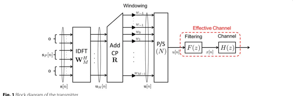
2 System model 2.1 Transmitter structure
Consider a multi-carrier system withMsubcarriers. Sup-pose that a communication device is allocated to a sub-band consisting ofPadjacent subcarriers. Figure1depicts
the block diagram of the transmitter. LetsP[n] denote the transmit symbol vector and assume
EsP[n]sHP[m] =
EsIP, n=m
0P×P, else
where Es denotes the symbol energy. Now, the trans-mit symbol vector is precoded by an IDFT matrixWHM, resulting in a vector uM[n]= WMHs[n] where s[n]=
0 sTP[n]0T.
To eliminate ISI and suppress the OOSBE, the vector
u[n] is obtained by adding a CP of lengthLtouM[n] and multiplying a matrix consisting of window coefficients. Specifically, the windowed signal vector is expressed as u[n]= diag([w−L · · · w0 · · · wM−1])RuM[n], where
wm,m= −L,· · ·,M−1 are the window coefficients, and matrixR, which represents adding the CP, is written as
R=
0L×(M−L) IL
IM
.
Now, define
Wejω=
M−1
m=−L
wme−j(m+L)ω (1)
as the Fourier transform of the window coefficients, then the power spectral density (PSD) of signal u[n], after parallel-to-serial (P/S) conversion of vectoru[n], is [26]
Suejω= Es N
k∈K
Wej(ω−k)2 (2)
whereN=M+L,k = 2MπkandKdenotes the set of sub-carriers that are actually used in a subband. LetKdenote the index of the subcarrier at the left of the allocated subband, then
K{K,K+1,· · ·,K+P−1}.
In conventional OFDM systems, the window coeffi-cients are usually chosen aswm=1,∀m= −L,· · ·,M−1 referred to as a rectangular window. In this paper, the
coefficients are considered to be more general, with a con-straint that the power of the signal using any arbitrary coefficients is equal to that using the rectangular window. That is,
M−1
m=−L
|wm|2=N. (3)
Note that the slope of sidelobe power decay of con-ventional OFDM signals is approximately proportional to the frequency distance to the center of the mainlobe [27]. The slow decay of sidelobe power in conventional OFDM systems results in large OOSBE.
An effective way of suppressing OOSBE is deploying per-subband filtering at the transmitter, which was first proposed in [18]. Subsequently, the windowed signalu[n] is filtered by an FIR filterF(z), which is defined as
F(z)=
Lf−1
n=0
f[n]z−n=vTL
f
z−1f
where f[n] is the impulse response and Lf denotes the filter length, which is assumed to be much smaller than the number of subcarriers, i.e., Lf M, and f =
f[0] f[1]· · · f[Lf −1] T
. Recall that the definition of
vLf(z)is given in Section1.3. Then, the PSD of the
trans-mitted signalx[n] is written as
Sxejω=Suejω Fejω2. (4) The filter function f[n] ,n = 0,· · ·,Lf −1, is chosen such that the expected value of the energy of the filtered signal x[n] is equivalent to that of the windowed signal
u[n]. Based on Parseval’s relation and (3),
π
−πSx
ejωdω
2π =
π
−πSu
ejωdω
2π =PEs. (5)
2.2 Effective channel
As illustrated in Fig.1, the filtered signalx[n] is sent over the channelH(z). It is assumed thatH(z)is an FIR channel with a maximum orderLh, i.e.,
H(z)=
Lh
n=0
h[n]z−n (6)
whereh[n] denotes the impulse response of the FIR chan-nel. By assuming that the transmitter and the receiver are perfectly synchronized, the signalu[n] can be viewed as passing through an effective channel, whose impulse response is written as
c[n]= Lf−1
l=0
f[l]h[n−l] ,n=0, 1,· · ·,Lc−1
whereLc= Lf +Lhis the length of the effective channel. Here, the CP length is assumed to be no smaller than the effective channel length, i.e.,L≥Lc, so that the ISI can be eliminated at the receiver [21].
2.3 Receiver structure
The modified zero-forcing receiver presented in [12] is adopted. Specifically, channel equalization in this paper is only performed on the subcarriers in the allocated sub-band, rather than on all the subcarriers, as presented in [12]. The block diagram of the receiver is depicted in Fig.2. As suggested in [21], receiver filtering in the original filtering-based waveform is not considered here in order to scale down the complexity of the receiver.
The received signal after serial-to-parallel (S/P) and CP removal is multiplied by the DFT matrix WM, and then channel equalization for signals on the used sub-carriers is performed by multiplying the inverse of the diagonal matrix(K). After that, the equalized signal is multiplied by the de-windowing matrixF(K)in order to restore the orthogonality between subcarriers in the sub-band. In [12], it has been proven that the de-windowing matrix F(K) is independent of the effective channel if the window satisfies the cyclic-prefixed property:
wm = wm+M,m = −1,−2,· · ·,−L. Based on this prop-erty, the windowed signal vector u[n] is mathematically equivalent to:
u[n]=RDuM[n] (7)
where D = diag(w) with w [w0w1 · · · wM−1]T.
Without regarding the signals of users allocated to other subbands, it can be shown that the vector yM[n], after serial-to-parallel conversion and CP removal, is
yM[n]=CDuM[n]+eM[n] (8)
where C is an M × M circulant matrix whose first column isc[ 0] c[ 1] · · · c[Lc−1] 0(M−Lc−1)
is the additive white Gaussian noise vector [28]. The circulant matrix can be diagonal-ized by the DFT matrix:
C=WHMWM (9)
where=diagCej0 Cej2Mπ
· · · Cej2Mπ(M−1)
with Cejω denoting the effective channel frequency response. Since the user is allocated to the subband con-sisting of subcarriers inK, equalization for the effective channel is only performed on the allocated subcarriers. Assuming that the receiver has perfect knowledge of effec-tive channel responses of the allocated subcarriers, the equalized vectorzP[n] is expressed as
zP[n]=−1(K)E(K)WMyM[n] (10) whereE(K)=[0P×(K−1) IP 0P×(M−P−K+1)], and(K)is the P×P diagonal matrix whose diagonal elements are the effective channel frequency responses of subcarriers inK. That is, the diagonal matrix is written as(K) = After equalization, to restore the orthogonality between subcarriers in the subband, de-windowing is performed so that the decoded symbol vectorsˆP[n] is written as
ˆ
sP[n]=F(K)zP[n] . (11)
whereF(K) E(K)FET(K). The matrixFis designed in a zero-forcing sense, which can be interpreted as trans-forming the equalized signal into a time-domain signal, by multiplying a diagonal matrix whose diagonal elements are the inverse of window coefficients, and then taking DFT on the product [12], i.e.,
F=WMD−1WHM. (12)
Such de-windowing operation will cause SNR loss at the receiver with an arbitrary wother than a constant-modulus window, e.g.,w=1M.
A different receiver structure that adopts de-windowing before channel equalization was proposed in [13]. This structure is not considered here because the adopted one assures orthogonality between subcarriers while data reception is executed at the receiver, and ISI is elim-inated given that L ≥ Lc. Moreover, the adopted structure is more suitable for performing window opti-mization because SNR loss caused by noise enhancement can be quantified explicitly, which will be presented in Section2.4.
2.4 Noise analysis
In this subsection, the SNR loss caused by de-windowing is derived, which plays an important role in window opti-mization. The derived SNR loss can be approximated as the same as that quantified in [12]. By substituting (8), (9), andF(K)in (11) into (10), the correlation matrix of vector
zP[n], after CP removal, DFT, and channel equalization, is written as matrix of noise after DFT and channel equalization. The
ith diagonal element ofzis written as
σ2
|2is the resulting noise
variance of the conventional OFDM system. After de-windowing is performed as in (11), the correlation matrix of ˆsP[n] is written asRˆs = EsIP + F(K)zFH(K). The output noise power of an entry in ˆsP[n] is the corre-sponding diagonal element of the latter term. After the de-windowing operation in (12), the total output noise power is written as
As a special case of the proposed waveform, filtering-based waveforms apply rectangular windowing. The resulting total output noise power is NF =
P
i=1σz2i,
which is obtained by substituting wm = 1,∀m ∈
{0,· · ·,M − 1} into (14). By letting F the total output noise of the conventional OFDM system is obtained asNC=Pi=1σi2.
To quantify the noise enhancement effect caused by de-windowing at the receiver compared to the conventional OFDM system, the SNR loss is defined as
σ(w)= NWF
K will degrade the bit error rate (BER) performance. Therefore, the passband ripple of transmit filtering is constrained tightly so that|F(ejk)|2≈1,∀k∈K.
R= NNF
C ≈
1 (16)
sinceσi2 ≈ σz2i,i = 1,· · ·,P. As a result, the SNR loss in (15) is approximated as
σ(w)≈ 1
In the sequel, it is assumed that the approximation in (16) holds given a tight passband ripple constraint. The reasons are that (i) this approximation is accurate for most of the channel responses and (ii) the approximation error does not affect the BER performance of the proposed waveform, as will be shown later in Sections5.3and5.7.
3 Problem statement
The goal of this paper is to jointly design the filterfand the windowwso that the OOSBE can be suppressed with a controllable SNR loss, and the passband ripple caused by filtering is restrained. The design is based on a min-imax criterion. In [29], it has been pointed out that a wide transition bandwidth (TBW) is beneficial to sup-pressing stopband magnitude for minimax-based filter design with specified filter length and passband ripple. This phenomenon suggests that the OOSBE suppression performance of a filtering-based waveform is limited with a fixed number of VCs, filter length, and passband rip-ple. Here, windowing is introduced to further improve the OOSBE suppression performance over the filtering-based waveforms.
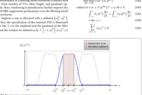
Suppose a user is allocated with a subband
ω(l)p ,ω(r)p
. Then, the specification of the transmit PSD is illustrated in Fig.3. Let the stopband and the passband of the filter and the window be defined asBs bands allocated to other users lie in the stopband such that the ICI between users can be mitigated. DefineBt
ω(l)s ,ω(l)p ]∪[ωp(r),ω(r)s
as the transition band. The sub-carriers in the transition band are treated as VCs. Letη denote the one-side normalized TBW, which is expressed as half the TBW over the subcarrier spacing (i.e., 2π/M), then the set of left and the right edges of the stopband are
nience,ηcan be thought of as the number of VCs on one side of the transition band.
Our design objective is to minimize the maximum (weighted) PSD in the stopband. The minimization is sub-ject to constraints of SNR loss and passband ripple. In addition, for fair comparison, the signals after window-ing and filterwindow-ing should not have any power amplification effect. Therefore, the constraints (3) and (5) should be sat-isfied. Based on the above requirements, the optimization problem is expressed as
where α and γ denote controllable parameters of pass-band ripple and SNR loss, respectively, andGejωis the weighting function of the stopband in order to meet a specified spectrum mask restriction. For simplicity, it is assumed thatGejω=1,∀ω∈Bsin the following
deriva-tions. When a more generalGejωis considered, how-ever, it may not impose too much difficulty in generalizing the derivations.
Here, problem (19) is formulated as a more compact form. Based on the cyclic-prefix window property, the Fourier transform of window coefficients in (1) can be written asWejω=vHNejωRw. Consequently, the PSD of signalu[n] is expressed as a quadratic form:
Suejω=wHBejωw (20)
where the positive semidefinite matrixBejωis
Bejω= Es
With this formulation, the original problem (19) is written as
min
This problem is nonconvex due to, e.g., constraints (22b), (22c), or (22e) [30]. Therefore, the well-developed convex optimization techniques [30] can not be applied directly to solve this problem. Instead of optimizingwand
fsimultaneously, a method is proposed to optimizewand
fiteratively.
4 Proposed method
In this section, an alternative optimization method to solve problem (19) is proposed. First, the problem (22) is divided into two subproblems, which are (i) optimiza-tion of filter: optimize the filter functionf, subject to filter constraints with a given window, and (ii)optimization of window: optimize the cyclic-prefixed window coefficients
wm,m = −L,· · ·,M−1, subject to window constraints with a given filter. Then, an iterative algorithm is pro-posed to solve the original optimization problem. The convergence and computational complexity of the pro-posed method, and the complexity of the transceiver are analyzed.
4.1 Optimization of filter function
The filter design method presented in [20] is used by relaxing the nonconvex problem into a convex one using spectral factorization [31]. The relaxed problem can be solved by using an interior-point method (IPM) in [30]. Given anywthat satisfies (22d) and (22e), problem (22) becomes a filter optimization problem written as
min This problem is nonconvex due to the lower-bounded constraint (23b) and the equality constraint (23c). This issue is overcome by using a technique presented in [32]. Let the auto-correlation function off[n] be defined as
rf(m)=
Lf−1
n=0
f[n]f∗[n+m] .
Then, the squared magnitude ofFejωcan be written as With this equation and some manipulations, the prob-lem (23) is modified as
constraints. A straightforward way of relaxing this prob-lem is to discretizeωby sampling a finite set of frequencies in [−π,π)such that
−π≤ ˇω0<· · ·<ωˇJ−1< π (29)
whereJdenotes the number of samples. This paper adopts uniformly spaced sampling, i.e., ωˇi = −π +2πi/J,i = 0, 1,· · ·,J−1. A previous work [33] recommended that
J ≈ 30Lf is sufficiently large to approximate the prob-lem (27). With this discretization, the filter optimization problem (27) is modified as
min existing toolboxes (e.g., cvx [34]). To obtainffrom the optimal rf, spectral factorization in [31] can be applied using an efficient implementation based on inverse fast Fourier transform (IFFT) and fast Fourier transform (FFT).
4.2 Optimization of window coefficients
A per-subband optimization method is proposed that minimizes the maximum stopband PSD subject to window constraints in (22), whereas per-subcarrier optimization was proposed in [12]. Specifically, the dow coefficients are restricted as real, and then the win-dow optimization problem is relaxed as a convex one. By adopting the technique presented in Section 4.1, prob-lem (22) is reformulated as
min The constraint (31c) is removed and the problem (22) is rewritten as constraint (31c) is removed are that (31c) is nonconvex in
win general, and the relaxation does not prevent us from finding the optimalwandffor problem (22), as will be explained in Section4.3.
In the literature, a common way of dealing with a complex value optimization problem is to reformulate it as a real-valued one via separating the real part and imaginary part of the parameters (e.g., [35, 36]). Define
ˆ mulated via separating the real and imaginary parts ofw, and relaxing (32c) as an inequality constraint so that this problem becomes a convex one. Then,
min
The convexity of this problem depends on constraint (34b), since the objective function and constraint (34b) are convex. The convexity ofσ (ˆ wˆ), domσˆ ⊆R2+Mis shown by
Proof See Appendix2.
implies that the original SNR loss functionσ(w), domσ = RM++, is convex, which is suggested by the proof of Theorem1(a). By applying frequency discretization as in (29) and (30), problem (34) is approximated as
wherew ∈ RM++. This problem is a convex optimization problem with finite constraints, which can be solved by usingcvx.
4.3 Proposed iterative method for joint optimization An iterative method that optimizes window and filter is proposed. In an iteration of the proposed method, the window optimization and filter optimization presented in the previous subsections are performed based on given fil-ter function and given window coefficients, respectively. Specifically, window optimization is performed based on the optimal filter’s auto-correlation function obtained in the previous iteration, and then filter optimization is per-formed based on the optimal window of the current iteration.
A detailed description of the proposed method is shown in Algorithm 1. In each iteration, the window optimiza-tion in (35) and the filter optimization (30) are performed sequentially. Letw(t) andrf(t)denote the optimal solu-tions of (35) and (30) in iteration t, respectively. The squared differences of the optimal filter’s correlation function vector and optimal window between iterationstand
t−1 are, respectively, written asξw(t)= w(t)−w(t−1)2 and ξr(t) = rf(t) − rf(t − 1)2. Since the pro-posed method is convergent (the proof will be given in Section 4.4), the squared differences ξw(t) and ξr(t) will decrease as the number of iterations increases. Therefore, the stopping criteria of the proposed itera-tive algorithm is that both ξw(t) and ξr(t) are smaller than pre-determined tolerances w and r, respec-tively. Let ˆt denote the termination iteration index. Then, the optimal window is w(ˆt), and the optimal fil-ter is obtained by performing spectral factorization [31] onrf(ˆt). For convenience, the starting point is given as
, which means that no trans-mit filtering is deployed. Other starting points have been tried, and the resulting performances in OOSBE suppression are close to or worse than that of the current one. Finding the optimal starting point is an open problem for alternative optimization algorithms [37,38], which is left for our future work.
In any iteration of the algorithm, the pairw(t),rf(t)
must satisfy the constraint (27c) after filter optimization.
Accordingly, the constraint (31c) is not necessary to be met by the windoww(t)based onrf(t−1). Therefore, it is removed from (31) in window optimization (32).
Algorithm 1Proposed iterative algorithm
Input: γ: the maximum SNR loss, K: the used subcar-rier set,α: the maximum ripple on used subcarriers,Bˇa:
the set of uniformly sampled frequencies,Bsˇ : the set of sampled stopband frequencies
4.4 Convergence analysis of the proposed algorithm It is necessary to characterize whether the proposed algo-rithm is convergent, since it is operated iteratively. To justify that the convergence of the proposed algorithm is guaranteed, it is sufficient to show that the iteration of updatingwandrf converges and the objective is lower-bounded. A similar argument can be found in [37, 38]. In each iteration, the optimalwis first obtained by solv-ing (35). The optimalrf is then computed by solving (30) based on the determinedw. Consequently, the objective function maxωˇ each iteration. Clearly, the objective function is lower-bounded because the stopband PSD is non-negative. Therefore, the proposed algorithm is convergent.
optimal filter from its auto-correlation function using an FFT-based implementation isOLflog2Lf
[31]. Sim-ilar to filter optimization, the computational complex-ity of the IPM for window optimization is expressed as OM3.5 [39]. As a result, the computational com-plexity in each iteration of the proposed iterative algo-rithm isO
r is independent from M. Therefore, the complexity order of the proposed method can also be expressed asOM3.5.
4.6 Complexity analysis of the transceiver
At the transmitter, the number of arithmetic operators of cyclic-prefixed windowing is expressed asO(M)because the windowed signal can be represented by (7); the num-ber of arithmetic operators of filtering is expressed as
ONLf
= ON2sinceLf is usually an integer equal to
Ndivided by a power of two and can possibly be reduced toO(Nlog2N)[40]. De-windowing at the receiver in (11) can be implemented by using FFT, IFFT, andMadditional multiplications. Therefore, the computational complexity of receiver with de-windowing isO(3Mlog2M+M) = O(Mlog2M), which is of the same order as the receiver of conventional OFDM.
5 Results and discussion
In this section, some numerical results are provided for demonstrating the advantages of the proposed waveform.
5.1 Parameter settings
The parameters used in our simulations are listed below:
• Total number of subcarriers:M=128
• Number of subcarriers in a subband:P=12
• Maximum channel order:Lh=M/8=16
• Filter length:Lf =17
• CP length:L=M/4=32
The values of the channel impulse response in (6) are assumed to be i.i.d. complex Gaussian random variables:
h[n]∼CN(0, 1),n=0, 1,· · ·,Lh.
There are 107channel realizations used in our simula-tions. It is assumed that all subcarriers in the subband are used, i.e.,K = {0, 1,· · ·,P−1}. The center frequency of the allocated subband isωc=(P−1)π/M. The passband
setωp(l),ω(r)p
, and the pair stopband edges,ω(l)s andω(r)s ,
are computed as Eq. (18) with arbitrary normalized TBWη.
In the following simulations, the proposed waveform is referred to as “joint windowing and filtering” (joint W-F).
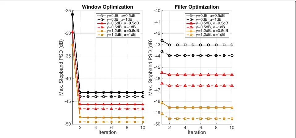
5.2 Convergence of the proposed algorithm
Figure 4 verifies the convergence of the proposed opti-mization method under different configurations. The nor-malized TBW used in this figure is η = 3.5. The left and right plots demonstrate that the objective function in (22) decreases and converges rapidly in each itera-tion after window optimizaitera-tion and filter optimizaitera-tion, respectively.
5.3 Approximation of SNR loss
To examine the accuracy of the approximation in (17) with respect to various passband ripple constraints, the histogram of the ratio R in (16), based on 107
arbi-trary channel realizations, is depicted in Fig.5, and the probability of the ratio falling in a range is shown in Table 1. The normalized TBW used here is also η = 3.5. One can observe that the ratios with α = 0.3 dB andα = 0.5 dB both have peak probabilities very close to R = 1. In addition, over 96% of the ratios with
α = 0.3 dB andα = 0.5 dB distribute in the range of
(−0.93, 1.07). These observations suggest that the approx-imation is tight for most of the channel realizations, and the approximation error imposes a slight affect on the BER performance, as will be shown in Section 5.7. On the contrary, the ratio with α = 1 dB leads to inac-curate approximation since its distribution is scattered in a much wider range and does not have a peak prob-ability close to R = 1. In summary, α = 0.5 dB is chosen for the following simulations because it results in an accurate SNR loss approximation and has a bet-ter OOSBE suppression performance than the case with
α=0.3 dB.
5.4 Related waveforms for comparison
To highlight the advantages of the proposed joint W-F waveform, the following related waveforms that use either windowing or filtering are introduced for comparison in our simulations.
(a) Pure filtering: The waveform deploys optimum filtering in [20] at the transmitter with rectangular windowing.
(b) Pure windowing: The waveform deploys optimum windowing without filtering at the transmitter. The optimal window is obtained through solving (35). (c) WOLA at the transmitter: Transmitter windowing of
Fig. 4Convergence of the proposed method
[Ch. 9]) is adopted for simulations. The raised-cosine (R-C) window is usually used by current WOLA systems, which is expressed as
wrc=
p0 · · · pν−1 1TN−ν pν · · · p2ν−1 T
where
pn=0.5
1−cos
n+1
ν π
,n=0,· · ·,ν−1,
andpn=1−pn−ν,n=ν,· · ·, 2ν−1[41] withν denoting the CS length. The receiver of WOLA is the same as that of the conventional OFDM system. To eliminate ISI introduced at the receiver, the CP length of WOLA should satisfyL≤Lh+ν. This paper assumes thatν=Lf for fair comparison.
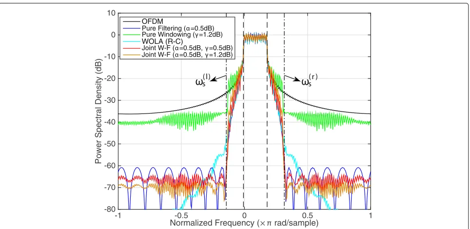
5.5 Normalized PSD
Here, the PSDs of the transmitted signals modulated by the aforementioned waveforms are demonstrated. The PSD is normalized so that its value on an allocated sub-band approaches 0 dB. The normalized PSD is written as
¯
Sxejω= 1 NEsSx
ejω.
Figures 6 and 7 depict the normalized PSDs of the proposed and the other waveforms. In Fig. 6, the nor-malized TBWs of the pure filtering, pure windowing, and the proposed waveforms are η = 8.5, which is as wide as that of WOLA. The resulting maximum stop-band PSD of the proposed waveform with SNR loss
γ = 1.2 dB is about −67 dB, which is the best per-formance compared to the others. With a little bit less SNR loss, the proposed waveform with γ = 0.5
Table 1Probability of the ratioRfalls in a range
Range ofRin (16) α=0.3 dB α=0.5 dB α=1 dB (0.97, 1.03) 0.8473 0.7465 0.3570 (0.95, 1.05) 0.9713 0.8897 0.5884 (0.93, 1.07) 0.9992 0.9615 0.7913
dB has a maximum stopband PSD performance of approx-imately 4 dB-larger than that of the one with γ = 1.2 dB, and it still outperforms other waveforms in suppress-ing maximum stopband PSD. In Fig. 7, the normalized TBWs of the proposed, pure filtering, and pure win-dowing waveforms are chosen as η = 3.5 so that less VCs are required. The proposed waveform using different SNR losses also outperforms other waveforms in sup-pressing maximum stopband PSD. Although WOLA has good stopband suppression performance for frequencies far from the passband, it will cause larger PSD at some fre-quencies near the stopband. Therefore, WOLA using R-C window will require more VCs to avoid possible ICI from other subbands compared to the proposed waveform.
5.6 Bandwidth efficiency
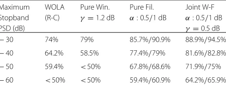
The proposed joint W-F waveform is more spectrally effi-cient than the other waveforms due to its capability of sup-pressing OOSBE to a specific level with a narrower guard band. As depicted in Fig. 3, the TBW is treated as the guard band between two adjacent subbands and is shared by two different users that are allocated to these sub-bands separately. Accordingly, the bandwidth efficiency is defined as
E(η)= P
P+η. (36)
Note that η denotes the normalized TBW over the bandwidth of a subcarrier, andPdenotes the number of subcarriers in a subband.
The bandwidth efficiency performance of the various waveforms is listed in Table 2. These waveforms pos-sess similar BER performances, which will be shown later. It is observed that the proposed waveform outperforms all the other waveforms at the price of approximately 0.5 dB SNR loss. Moreover, the proposed and the pure filtering waveforms can obtain better performances by relaxing the passband ripple constraint. These obser-vations not only show the superiority of the proposed waveform in suppressing OOSBE spectral-efficiently but also suggest that the proposed optimization method offers more flexibility in designing the transmission waveform.
5.7 Single-user BER simulations
BER is considered as a metric for the performance of data transmission and reception in our simulations. QPSK or 16QAM without channel coding [42] is adopted as the modulation scheme with gray-coded symbols. Here, the simulations are executed based on the following cases.
(a) ISI-free case: The CP length is sufficient to eliminate ISI, and the transmitter is perfectly synchronized with the receiver. In this case, the proposed waveform,
Fig. 7PSD of various types of waveforms (η=3.5)
compared to OFDM, WOLA, and the pure filtering waveform, has a 0.5 dB BER disadvantage, which is roughly equal to the SNR loss. This phenomenon suggests that the proposed waveform trades a slight SNR loss for the advantageous bandwidth efficiency as shown in Table2.
(b) ISI-incurring case: The CP length is insufficient so that there is ISI incurred at the receiver, and the transmitter is perfectly synchronized with the receiver. In this case, the proposed waveform is less prone to ISI compared to the pure filtering waveform (and WOLA) because it requires a shorter filter to achieve the same OOSBE suppression level.
Therefore, the proposed waveform can use a shorter CP to mitigate ISI, which makes it more spectrally efficient than the pure filtering waveform and WOLA.
The results of the ISI-free case are shown in Figs. 8 and9. In the simulations, the normalized TBW is set as
η=3.5. It is observed that the pure filtering waveform and
Table 2Bandwidth efficiency comparison
Maximum WOLA Pure Win. Pure Fil. Joint W-F Stopband (R-C) γ=1.2 dB α: 0.5/1 dB α: 0.5/1 dB
PSD (dB) γ=0.5 dB
−30 74% 79% 85.7%/90.9% 88.9%/94.5% −40 64.2% 58.5% 77.4%/79% 81.6%/82.8% −50 59.4% <50% 67.8%/68.6% 71.9%/75% −60 <50% <50% 59.4%/60.9% 64.2%/65.9%
WOLA have BER performances similar to that of OFDM. The pure windowing waveform has an exact 1.2 dB disad-vantage. Although the proposed waveform has an approx-imately 0.5 dB disadvantage (approxapprox-imately equal to the SNR loss), it possesses the best OOSBE suppression per-formance as shown in Figs.6and7. This advantage will be further demonstrated in Section5.8.
In Figs.10and11, the results of the ISI-incurring case are demonstrated. Here, the CP length is set asL = 23. The filter lengths of the pure filtering and the proposed waveforms are set as Lf = L = 23 and Lf = 17, respectively. They are chosen this way so that the two waveforms possess a similar maximum stopband PSD of approximately −44 dB. The CS length of WOLA is
Fig. 8ISI-free BER performances (QPSK)
5.8 Asynchronous multi-user BER simulations
Here, BER simulations are performed based on an asyn-chronous uplink scenario with multiple users modulated by the same waveform. The proposed waveform has the best performance especially in this scenario.
As suggested in [1–3], the requirement of relaxed frequency synchronization is based on the necessity of deploying a waveform with reduced OOSBE compared to conventional OFDM. Therefore, frequency asynchronism caused by carrier frequency offsets (CFOs) is introduced in our simulations. In [2], it was pointed out that the CFO
of a user can be estimated and compensated at the receiver without requiring any information feedback from the user. Some example methods of estimating CFOs can be found in [43,44]. However, ICI will still occur because various CFOs of users are unable to be compensated for at the same time.
Suppose there are three users transmitting data sym-bols simultaneously, as illustrated in Fig.3. The CFO of the user allocated to subbandKis assumed to be perfectly estimated and compensated for at the receiver, while the other two users are allocated to neighboring subbands
Fig. 10ISI-incurring BER performances (QPSK)
and are asynchronous to the receiver, i.e., the CFOs of the neighboring users are not compensated for. Specifi-cally, the two neighboring users, indexed user 1 and user 2, are allocated to subbands K1 {−P − η,−P − η−
1,· · ·,−1−η} andK2 {P+η,P+η+1,· · ·, 2P+
η−1}, respectively. The data symbols of the two users are denoted ass(P1)[n], ands(P2)[n], respectively. The pre-coded data symbols of userlbefore adding CP are denoted as u(l)M[n]= WHMET(Kl)s(l)P [n] ,l = 1, 2. The window
coefficients deployed by each user are the same; the filter functions used by user 1 and user 2, denotedf(1)[n] and
f(2)[n], respectively, are the frequency-shifted versions of the optimal filter function to the center frequencies of the allocated subbands, i.e.,
f(1)[n]=f[n]e−j2Mπ(P+η)n,n=0, 1,· · ·,Lf −1
and f(2)[n]=f[n]ej2Mπ(P+η)n,n=0, 1,· · ·,Lf −1.
Fig. 12Multi-user BER performances with CFOs (QPSK)
Lethl[n]∼ CN(0, 1),n= 0, 1,· · ·,Lhdenote the chan-nel impulse response of userl, then the resulting effective channel iscl[n]=hl[n]∗f(l)[n] where∗denotes the oper-ation of convolution. For simplicity, the CP length is assumed to be sufficient to eliminate ISI. In the presence of CFO, the received signal vector after serial-to-parallel conversion and CP removal is expressed as
yM[n]=CDuM[n]+
2
l=1
(εl)ClDu(l)M[n]+eM[n]
where (εl) diag
1ej2Mπεl · · · ej2Mπ(M−1)εl
is the matrix representing phase shift incurred by the CFO,εl denotes the normalized CFO of userl, andClis the cir-culant matrix consisting the effective channel’s impulse response of userl[44]. The decoding ofsP[n] is the same as performed in (10) and (11).
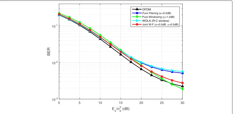
In Figs.12and13, the BER simulation results of the user allocated to subbandKare demonstrated. Here, the nor-malized CFOs are expressed as i.i.d. uniformly distributed random variables in the range of [−φ,φ], as suggested in [44], where φ = 0.1. The normalized TBW is η = 1.
Fig. 14BER performance with ETU channel model (16QAM,L=16)
The other parameters are set as presented in Section5.1. The maximum stopband PSD of the proposed waveform (SNR lossγ = 0.5 dB), the pure filtering waveform, and the pure windowing waveform are−28.67 dB,−24.51 dB, and −20.87 dB, respectively. One can observe that the proposed waveform outperforms other waveforms sig-nificantly when Eb/σ2
e is larger than 12.5 dB. This is because the proposed waveform has the best capability
of suppressing OOSBE so that ICI introduced by CFOs can be greatly mitigated. Due to rectangular window-ing and inferior capabilities in OOSBE suppression, the BER performances of OFDM, WOLA, and pure filtering waveform are similar. The pure windowing waveform has the worst BER performance since it will cause severe ICI due to destroying the orthogonality between sub-carriers. In regimes of lower transmitting energy, i.e.,
Table 3Comparison of the waveforms
OFDM Pure Win. Pure Fil. WOLA Joint W-F OOSBE Large Medium Small Small Very small SNR loss None Large None None Small CP extention for
None None Long Long Short ISI mitigation
# of VCs for Very
Large Small Small Very small ICI mitigation Large
Eb/σe2 ≤ 12.5 dB, the proposed waveform has a slight performance disadvantage compared to WOLA, the pure filtering waveform, and the conventional OFDM. This is because the BER performance of the zero-forcing receiver is more prone to noise rather than ICI in such regimes. These results suggest that the proposed waveform is more capable of suppressing ICI for asynchronous transmis-sions than other waveforms.
5.9 BER simulations with ETU channel model
BER simulations are executed based on the extended typ-ical urban (ETU) channel model [45]. The results are demonstrated in Figs.14and15. In these figures, the sam-pling frequency is 1.92 MHz, the velocity of the UE is 3 km/h, the number of subcarriers isM=128, andη=1. The filter length of the proposed joint W-F method is
Lf =9, andν =Lf for WOLA in both figures. In Fig.14, the CP lengths of all the waveforms are set asL=16, and the filter length of the pure filtering one isLf =9. One can observe that the joint W-F method also has a 0.5 dB per-formance disadvantage comparing with OFDM, WOLA, and the pure filtering method, which is the same as what was demonstrated in Fig.9. In Fig.15, the CP lengths of all the waveforms are set asL=8, and the filter length of the pure filtering one isLf =9. The filter lengths are cho-sen so that the pure filtering and the proposed waveforms possess a similar maximum stopband PSD of approxi-mately−31 dB. In this figure, it is also observed that the proposed waveform outperforms the pure filtering wave-form and WOLA in the presence of ISI at the receiver, as demonstrated in Fig.11.
6 Conclusions
In this paper, a joint windowing and filtering multi-carrier waveform was proposed. An iterative method for joint optimization was also proposed to minimize the OOSBE with controllable SNR loss at the receiver. In contrast with the previous pure filtering and pure windowing waveforms, the proposed waveform has an advantage in suppressing OOSBE to a lower level with similar BER per-formances. This advantage indicates that the proposed waveform is more spectrally efficient when suppress-ing OOSBE than the other waveforms. Moreover, the
proposed waveform requires a shorter filter length and induces less SNR loss for achieving an OOSBE suppres-sion specification compared to previous pure filtering and pure windowing waveforms, respectively. The detailed comparison of the proposed waveform with OFDM, the pure filtering waveform, the pure windowing waveform, and WOLA is presented in Table 3. Simulation results support the above advantages of the proposed waveform.
Channel estimation and peak-to-average power ratio (PAPR) reduction remain as open problems. Extending the proposed waveform to a multiple-input-multiple-output system is also of interest.
Appendix 1: Derivation of constraint (27c)
By substituting (24) into (4), the PSD of the transmitted signalx[n] is expressed as
Appendix 2: Proof of Theorem1
Followed by the argument of domσˆ, define convex ifg is convex. The convexity of g is shown by its second-order condition [30]. By taking the second-order derivatives ofg, the Hessian is written as
∇2g(τ)= 6
which is a positive definite matrix. Therefore,σ (ˆ wˆ)is convex.
(b) By taking second-order derivatives ofσˆ, the Hessian is given by Hessian matrix∇2σ(ˆ wˆ)is not positive semidefinite. This property can be shown by considering the following example:wˆ = √1
212M. The resulting minimum eigenvalue of the Hessian is−2/M. Therefore, the functionσˆ is nonconvex.
Abbreviations
CFO: Carrier frequency offset; CP: Cyclic prefix; CS: Cyclic suffix; DFT: Discrete fourier transform; f-OFDM: Filtered-OFDM; FBMC: Filter bank multi-carrier; FFT: Fast fourier transform; FIR: Finite impulse response; GFDM: Generalized frequency division multiplexing; ICI: Inter-carrier interference; IFFT: Inverse FFT; IPM: Interior-point method; ISI: Inter-symbol interference; OFDM: Orthogonal frequency division multiplexing; OOSBE: Out-of subband emissions; PAPR: Peak-to-average power ratio; PSD: Power spectral density; R-C: Raised-cosine; SNR: Signal-to-noise ratio; TBW: Transition bandwidth; UFMC: Universal-filtered multi-carrier; VC: Virtual carrier; WOLA: Weighted overlap-and-add
Acknowledgements
The authors would like to thank Dr. Gordon L. Stüber, Joseph M. Pettit Chair Professor of ECE department, Georgia Institute of Technology, for his valuable comments that significantly improved the quality of this paper.
Funding
This work is supported by the Ministry of Science and Technology, Taiwan, under contracts MOST 106-2221-E-002-034.
Availability of data and materials
Not available online. Please contact author for data requests.
Authors’ contributions
MFT made the main contributions to the joint window and filter optimization algorithms’ design and experiments, as well as drafting the manuscript. BCS checked the manuscript and offered critical suggestions to design the algorithm. Both authors read and approved the final manuscript.
Competing interests
The authors declare that they have no competing interests.
Publisher’s Note
Springer Nature remains neutral with regard to jurisdictional claims in published maps and institutional affiliations.
Author details
1Graduate Institute of Communication Engineering, National Taiwan
University, No.1, Sec. 4, Roosevelt Road, Taipei 10617, Taiwan.2Department of
Electrical Engineering, National Taiwan University, No.1, Sec. 4, Roosevelt Road, Taipei 10617, Taiwan.
Received: 6 February 2018 Accepted: 29 August 2018
References
1. J. G. Andrews, S. Buzzi, W. Choi, S. V. Hanly, A. Lozano, A. C. K. Soong, J. C. Zhang, What will 5G be?. IEEE J. Sel. Areas Commun.32(6), 1065–1082 (2014)
2. G. Wunder, P. Jung, M. Kasparick, T. Wild, F. Schaich, Y. Chen, S. T. Brink, I. Gaspar, N. Michailow, A. Festag, L. Mendes, N. Cassiau, D. Ktenas, M. Dryjanski, S. Pietrzyk, B. Eged, P. Vago, F. Wiedmann, 5GNOW:
non-orthogonal, asynchronous waveforms for future mobile applications. IEEE Commun. Mag.52(2), 97–105 (2014)
3. X. Zhang, L. Chen, J. Qiu, J. Abdoli, On the waveform for 5G. IEEE Commun. Mag.54(11), 74–80 (2016)
4. A. A. Zaidi, R. Baldemair, H. Tullberg, H. Bjorkegren, L. Sundstrom, J. Medbo, C. Kilinc, I. D. Silva, Waveform and numerology to support 5G services and requirements. IEEE Commun. Mag.54(11), 90–98 (2016) 5. L. Zhang, A. Ijaz, P. Xiao, A. Quddus, R. Tafazolli, Subband filtered
multi-carrier systems for multi-service wireless communications. IEEE Trans. Wirel. Commun.16(3), 1893–1907 (2017)
6. L. Zhang, A. Ijaz, P. Xiao, R. Tafazolli, Multi-service system: an enabler of flexible 5G air interface. IEEE Commun. Mag.55(10), 152–159 (2017) 7. P. Guan, D. Wu, T. Tian, J. Zhou, X. Zhang, L. Gu, A. Benjebbour, M.
Iwabuchi, Y. Kishiyama, 5G field trials: OFDM-based waveforms and mixed numerologies. IEEE J. Sel. Areas Commun.35(6), 1234–1243 (2017) 8. B. Farhang-Boroujeny, OFDM versus filter bank multicarrier. IEEE Signal
Proc. Mag.28(3), 92–112 (2011)
9. X. Mestre, M. Majoral, S. Pfletschinger, An asymptotic approach to parallel equalization of filter bank based multicarrier signals. IEEE Trans. Signal Process.61(14), 3592–3606 (2013)
10. M. Pauli, P. Kuchenbecker, inProc. IEEE Int. Conf. Commun., vol. 3. On the reduction of the out-of-band radiation of OFDM-signals (IEEE, Atlanta, 1998), pp. 1304–1308
11. Y. Medjahdi, R. Zayani, H. Shaïk, D. Roviras, in2017 IEEE International Conference on Communications Workshops ICC Workshops). WOLA processing: a useful tool for windowed waveforms in 5G with relaxed synchronicity (IEEE, Paris, 2017), pp. 393–398
12. Y.-P. Lin, S. M. Phoong, Window designs for DFT-based multicarrier systems. IEEE Trans. Signal Process.53(3), 1015–1024 (2005) 13. D. Roque, C. Siclet, Performances of weighted cyclic prefix OFDM with
low-complexity equalization. IEEE Trans. Commun.17(3), 439–442 (2013) 14. N. Michailow, M. Matthé, I. S. Gaspar, A. N. Caldevilla, L. L. Mendes, A.
Festag, G. Fettweis, Generalized frequency division multiplexing for 5th generation cellular networks. IEEE Trans. Commun.62(9), 3045–3061 (2014)
15. H. M. Chen, W. C. Chen, C. D. Chung, Spectrally precoded OFDM and OFDMA with cyclic prefix and unconstrained guard ratios. IEEE Trans. Wirel. Commun.10(5), 1416–1427 (2011)
16. M. Ma, X. Huang, B. Jiao, Y. J. Guo, Optimal orthogonal precoding for power leakage suppression in DFT-based systems. IEEE Trans. Commun.
59(3), 844–853 (2011)
17. A. Farhang, N. Marchetti, L. E. Doyle, Low-complexity modem design for GFDM. IEEE Trans. Signal Process.64(6), 1507–1518 (2016)
18. V. Vakilian, T. Wild, F. Schaich, S. ten Brink, J. F. Frigon, in2013 IEEE Globecom Workshops (GC Wkshps). Universal-filtered multi-carrier technique for wireless systems beyond LTE (IEEE, Atlanta, 2013), pp. 223–228 19. T. Wild, F. Schaich, Y. Chen, in2014 19th International Conference on Digital
Signal Processing. 5G air interface design based on universal filtered (UF-)OFDM (IEEE, Hong Kong, 2014), pp. 699–704
20. M.-F. Tang, B. Su, in2016 IEEE International Conference on Communications Workshops (ICC). Filter optimization of low out-of-subband emission for universal-filtered multicarrier systems (IEEE, Kuala Lumpur, 2016), pp. 468–473
21. L. Zhang, P. Xiao, A. Quddus, Cyclic prefix-based universal filtered multicarrier system and performance analysis. IEEE Trans. Signal Process.
22. J. Abdoli, M. Jia, J. Ma, in2015 IEEE 16th International Workshop on Signal Processing Advances in Wireless Communications (SPAWC). Filtered OFDM: a new waveform for future wireless systems (IEEE, Stockholm, 2015), pp. 66–70
23. X. Zhang, M. Jia, L. Chen, J. Ma, J. Qiu, in2015 IEEE Global Communications Conference (GLOBECOM). Filtered-ofdm - enabler for flexible waveform in the 5th generation cellular networks (IEEE, San Diego, 2015), pp. 1–6 24. P. Weitkemper, J. Bazzi, K. Kusume, A. Benjebbour, Y. Kishiyama, in2016
IEEE International Conference on Communications Workshops (ICC). Adaptive filtered OFDM with regular resource grid (IEEE, Kuala Lumpur, 2016), pp. 462–467
25. D. J. Han, J. Moon, D. Kim, S. Y. Chung, Y. H. Lee, Combined
subband-subcarrier spectral shaping in multi-carrier modulation under the excess frame length constraint. IEEE J. Sel. Areas Commun.35(6), 1339–1352 (2017)
26. Y.-P. Lin, S.-M. Phoong, P. Vaidyanathan,Filter bank transceivers for OFDM and DMT systems. (Cambridge University Press, Cambridge, United Kingdom, 2010)
27. J. A. Zhang, X. Huang, A. Cantoni, Y. J. Guo, Sidelobe suppression with orthogonal projection for multicarrier systems. IEEE Trans. Commun.
60(2), 589–599 (2012)
28. P. P. Vaidyanathan,Multirate systems and filter banks. (Prentice-Hall, New Jersey, 1993)
29. K. Ichige, M. Iwaki, R. Ishii, Accurate estimation of minimum filter length for optimum FIR digital filters. IEEE Trans. Circ. Syst. II: Analog Digit. Signal Process.47(10), 1008–1016 (2000)
30. S. Boyd, L. Vandenberghe,Convex optimization. (Cambridge university press, Cambridge, United Kingdom, 2004)
31. A. Papoulis,Signal analysis vol. 191. (McGraw-Hill, New York, 1977) 32. S.-P. Wu, S. Boyd, L. Vandenberghe, inProceedings of 35th IEEE Conference
on Decision and Control, vol. 1. FIR filter design via semidefinite programming and spectral factorization (IEEE, Kobe, 1996), pp. 271–276 33. A. S. Alkhairy, K. G. Christian, J. S. Lim, Design and characterization of
optimal FIR filters with arbitrary phase. IEEE Trans Signal Process.41(2), 559–572 (1993)
34. M. Grant, S. Boyd, CVX: MATLAB Software for disciplined convex programming, version 2.1 (2014).http://cvxr.com/cvx
35. R. G. Lorenz, S. P. Boyd, Robust minimum variance beamforming. IEEE Trans. Signal Process.53(5), 1684–1696 (2005)
36. Z. L. Yu, W. Ser, M. H. Er, Z. Gu, Y. Li, Robust adaptive beamformers based on worst-case optimization and constraints on magnitude response. IEEE Trans. Signal Process.57(7), 2615–2628 (2009)
37. S. W. Peters, R. W. Heath, in2009 IEEE International Conference on Acoustics, Speech and Signal Processing. Interference alignment via alternating minimization (IEEE, Taipei, 2009), pp. 2445–2448
38. L. Kong, S. Han, C. Yang, Hybrid Precoding With Rate and Coverage Constraints for Wideband Massive MIMO Systems. IEEE Trans. Wirel. Commun.17(7), 4634–4647 (2018)
39. M. Colombo, J. Gondzio, Further development of multiple centrality correctors for interior point methods. Comput. Optim. Appl.41(3), 277–305 (2008)
40. T. Wild, F. Schaich, in2015 IEEE 81st Vehicular Technology Conference (VTC Spring). A reduced complexity transmitter for UF-OFDM (IEEE, Glasgow, 2015), pp. 1–6
41. G. Cuypers, K. Vanbleu, G. Ysebaert, M. Moonen, P. Vandaele, in Communications, 2003. ICC ’03. IEEE International Conference On, vol. 4. Combining raised cosine windowing and per tone equalization for RFI mitigation in DMT receivers (IEEE, Anchorage, 2003), pp. 2852–28564 42. J. G. Proakis,Digital communications, 4th edn. (McGraw-Hill, New York,
2001)
43. H. T. Hsieh, W. R. Wu, Blind maximum-likelihood carrier-frequency-offset estimation for interleaved OFDMA uplink systems. IEEE Trans. Veh. Technol.60(1), 160–173 (2011)
44. X. N. Zeng, A. Ghrayeb, Joint CFO and channel estimation for OFDMA uplink: an application of the variable projection method. IEEE Trans. Wirel. Commun.8(5), 2306–2311 (2009)