Volume 2006, Article ID 47938, Pages1–12 DOI 10.1155/WCN/2006/47938
A Robust Parametric Technique for Multipath Channel
Estimation in the Uplink of a DS-CDMA System
Vassilis Kekatos,1Athanasios A. Rontogiannis,2and Kostas Berberidis1
1Department of Computer Engineering and Informatics and Research Academic Computer Technology Institute,
University of Patras, 26500 Rio Patras, Greece
2Institute of Space Applications and Remote Sensing, National Observatory of Athens, 15236 Palea Penteli, Athens, Greece
Received 9 November 2004; Revised 22 November 2005; Accepted 28 December 2005
Recommended for Publication by Soura Dasgupta
The problem of estimating the multipath channel parameters of a new user entering the uplink of an asynchronous direct sequence-code division multiple access (DS-CDMA) system is addressed. The problem is described via a least squares (LS) cost function with a rich structure. This cost function, which is nonlinear with respect to the time delays and linear with respect to the gains of the multipath channel, is proved to be approximately decoupled in terms of the path delays. Due to this structure, an iterative pro-cedure of 1D searches is adequate for time delays estimation. The resulting method is computationally efficient, does not require any specific pilot signal, and performs well for a small number of training symbols. Simulation results show that the proposed technique offers a better estimation accuracy compared to existing related methods, and is robust to multiple access interference.
Copyright © 2006 Vassilis Kekatos et al. This is an open access article distributed under the Creative Commons Attribution License, which permits unrestricted use, distribution, and reproduction in any medium, provided the original work is properly cited.
1. INTRODUCTION
Direct sequence-code division multiple access (DS-CDMA) is a widely accepted multiple access technique already in use in several real-life systems, such as the universal mobile telecommunications standard (UMTS). Among its proper-ties, that is, low power, high capacity, resistance to multipath, the latter is perhaps the most favourable. However, in many cases, in order to perform equalization, diversity combining, or multiuser detection at the receiver of a DS-CDMA system, knowledge of the multipath channel impulse response (CIR) is necessary. Thus, an efficient and accurate estimation of the CIR is highly desirable, in order to mitigate interference and achieve reliable data detection.
The wireless channel can be characterized either by the conventional tapped-delay line (TDL) model or by a para-metric model where the CIR is expressed in terms of time delays and gains of dominant paths. As the chip rate in-creases, the channel experienced by DS-CDMA systems be-comes sparse, making the parametric model more eff ec-tive, since fewer parameters are adequate for accurate chan-nel representation. Moreover the parametric model is more suitable for receiver structures such as RAKE [1], and for po-sitioning purposes.
The channel estimation task becomes more difficult at the uplink due to the multiple access nature of DS-CDMA systems. In the presence of multipath, it is difficult to time synchronize mobile transmitters so that their signals arrive simultaneously at the base station (BS). Thus, the uplink of DS-CDMA systems is usually asynchronous, the orthogonal-ity of signature sequences is violated, and multiple access in-terference (MAI) affects seriously channel estimation accu-racy.
training signals and model MAI as colored noise. In [11,12] interfering users are considered unknown at the BS, whereas in [13–15] channel estimates from MAI users are exploited during the estimation of a new user, but specific PN se-quences are required. The only method that uses relatively few training symbols, exploits available information con-cerning other active users, and does not require specific sig-nals to be employed, is the one proposed in [16]. The method in [16] follows an ML-based approach and employs a de-flation scheme originating from the SAGE algorithm [17]. Specifically, the optimization is performed with respect to a single path, and after this path has been estimated, its con-tribution is subtracted from the received data. The deflation scheme applies similarly to the rest of the paths.
In this paper we propose a new method for estimating the multipath delays and gains in the uplink of a DS-CDMA system. First, we show that the estimation problem can be described via a nonlinear least squares (LS) cost function, which is separable with respect to the unknown parameter sets, that is, time delays and gains. Then, we prove that the time delays’ cost function is approximately decoupled, which allows the development of a computationally efficient lin-ear slin-earch method for the estimation of the unknown time delays. Finally, the gain parameters are estimated by solv-ing a low-order linear LS problem. The new method consti-tutes an interesting alternative interpretation of the channel parameters’ estimation problem. Moreover, the problem is formulated in a novel way allowing for easier analysis and manipulations. Simulations results show that the proposed method exhibits a lower mean squared estimation error than the method of [16], at the expense of a negligible increase of the computational complexity.
The outline of this paper is as follows. InSection 2, the signal model is defined and the estimation problem is for-mulated. InSection 3, the LS cost function is derived and the proposed algorithm is developed. Simulation results are presented inSection 4, while some conclusions are drawn in Section 5.
2. PROBLEM FORMULATION
Let us consider the reverse link of a DS-CDMA system ac-commodatingKsimultaneously active users. IfTis the sym-bol period,{bk(i)} the transmitted symbols, and pk(t) the
spreading waveform of kth user, then the baseband signal transmitted by this user can be expressed as
sk(t)=
LetN be the spreading factor, Tc = T/N the chip period,
{ck(n),n = 0,. . .,N−1} the chip sequence, andg(t) the
chip pulse. Then, the spreading waveformpk(t) is given by
pk(t)=
The signal sk(t) of each user is transmitted over a
specu-lar multipath channel withP discrete paths having impulse
response
respectively, and δ(·) is the Dirac function. The signal re-ceived by the BS is the superposition of the signals from all users, that is,
contaminated by additive, white, Gaussian noise w(t) of power spectral density N0. The received signal is oversam-pled by a factor ofQsamples per chip period, while a raised cosine function is used as the chip pulse.1
The delay spread of the physical channelhk(t), usually
encountered in the applications of interest, is restricted to a few chip periods [18]. Also, taking into account the asyn-chronous access of thekth user to the channel, the first delay
τk,1could appear anywhere in the interval [0,NTc) of the BS
timing. Thus, a time support of two symbols can be adequate for the total CIR, which is the convolution of the physical channel,hk(t), with the chip sequence{ck(n)}.
Our goal is the estimation of the physical channel param-eters for one user assuming that the paramparam-eters of all other (K−1) users have already been estimated. To this end and using the formulation presented above, the samples collected at the BS receiver over a period ofMsymbols can be written in vector form as
x=
2N ×2N convolution matrix with its first row containing the chip sequence as [cT
k 0TN],cTk = [ck(0),. . .,ck(N −1)],
andG(τk) is a 2QN×Pmatrix whose columns contain the
oversampled delayed chip pulses denoted in vector form as g(τk,p), p = 1,. . .,P. Note that each column of G(τk) is a
function of a single delay parameter only. Symbol⊗stands for the Kronecker product andIQ is theQ×Qidentity
ma-trix.
Considering that a new user (called hereafter the desired user) is entering the system, (5) can be rewritten as
x=S(τ)a+η, (7)
where the user index has been dropped for simplicity2 and η comprises the MAI from previously estimated users and thermal noise.
We assume that the spreading sequences of all the users are known at the BS, while the desired user is in training mode and has been synchronized to the BS. Although the channel parameters of the interfering users have already been estimated, their symbol sequences have not been detected yet. Hence, MAI can be treated as a stochastic random pro-cess [16]. Specifically, MAI vectorηcan be modelled as a zero mean Gaussian vector with covariance matrixRη =E[ηηH].
Since the channel parameters and the signature sequences of the interfering users are deterministic, the expectation op-erator is applied over the transmitted symbols and thermal noise.
Having defined the problem, we proceed with the defini-tion of the cost funcdefini-tion appearing in the estimadefini-tion problem and the derivation of the new algorithm.
3. DERIVATION OF THE NEW ALGORITHM
3.1. The new cost function
As can been seen from (7), the data available for the esti-mation of channel parameters are contaminated by colored noiseηwith covariance matrixRη (the estimation ofRη is
further discussed in the appendix). Hence, a first step for the derivation of the new cost function would be the prewhiten-ing of additive noise as
Rη−1/2x=R−η1/2S(τ)a+R−η1/2η, (8)
whereR−1/2
η is a square root factor ofR−η1. Now, the required
channel parameters may be estimated by minimizing the fol-lowing least squares (LS) cost function with respect toτand a:
J(τ,a)=R−η1/2x−R−η1/2S(τ)a
2
. (9)
The cost function in (9) is linear with respect to the path gains and nonlinear with respect to the delays. Since the two sets of parameters are independent, the optimization prob-lem can be split up with respect to each set [19], that is,
τopt=arg max
τ
R−1/2
η S(τ)
R−1/2
η S(τ)
† R−1/2
η x
2 , (10)
aopt=R−η1/2S(τ)
†
R−η1/2x, (11)
where symbol†denotes the pseudoinverse of a matrix. It is apparent that the most difficult part of the above op-timization procedure is the maximization in (10). After the optimum delay parameters have been estimated, path gain parameters can be easily computed through (11). The non-linear problem (10) can be treated either by performing a
2The user index is also omitted from all relevant quantities throughout the
rest of the paper.
multidimensional search over the parameter space ofτ, or by applying an iterative Newton-type method. In the former case, the computational cost is prohibitive, whereas in the latter, the method can be trapped in a local maximum away from the global solution.
In the following, we show that the estimation of each de-lay parameterτp,p =1,. . .,P can be performed separately
leading to a much more efficient estimation algorithm. We begin by rewriting the cost function in (10) as
F(τ)=yH(τ)D(τ)y(τ), (12) where
y(τ)=SH(τ)R−1
η x, D(τ)=
SH(τ)R−1
η S(τ)
−1
.
(13)
It is readily seen from (6) that each column of S(τ) depends on a single delay parameter, that is, S(τ) = [s(τ1)· · ·s(τP)]. Then it is obvious that the same property
holds for the elements of vectory(τ) as well. Based on this observation, we deduce that the cost function F(τ) would be decoupled with respect to the delay parameters, if ma-trixD(τ) were diagonal and each element [D(τ)]i,iwere
as-sociated only to the corresponding delay parameterτi. Even
though matrixD(τ) is not exactly diagonal, we show that it is strongly diagonally dominant, yielding to an approximate decoupling of the cost function (10) with respect to the delay parameters.
To this end, we invoke a proposition proved in [20,21].
Proposition 1. Let a matrixA∈Cn×nand letr
Abe the mean
ratio of its off-diagonal and diagonal elements.3If this matrix is
pre/post multiplied by a unitary matrixQ∈Cn×mandmn,
then the resulting matrixB = QHAQ(and its inverse) have
smaller mean ratios upper bounded byrB≤(m/n)rA.
Consequently, if matrixAhas diagonal elements of much higher amplitude than the off-diagonal ones, andm n, then matrixBand its inverse are strongly diagonally domi-nant. To apply the aforementioned proposition in our prob-lem, for example, for matrixD(τ) in (12), three conditions should be satisfied.
(1) PMQN, which always holds true. (2) MatrixR−1
η should have a “heavy” diagonal.
(3) MatrixS(τ) should possess a unitary structure.
The second condition is proved in the appendix, where we show that the amplitude of the diagonal elements ofR−1
η
is much higher than the amplitude of the off-diagonal ones. Concerning the last condition, from (6), after some algebra, we get
SH(τ)S(τ)=GT(τ)C⊗I Q
BBH⊗I
QN
CH⊗I
Q
G(τ).
(14)
3The mean ratio rA of a matrix A ∈ Cn×n is defined as rA =
E[j=i|ai,j|/|ai,i|], where the expectation is applied over the rowsi =
The termBBHis the sample covariance matrix of the
infor-mation symbols, and can be approximated asymptotically by the identity matrixI2, so (14) is reduced to
SH(τ)S(τ)GT(τ)CCH⊗I Q
G(τ). (15)
Moreover, the termCCHapproximates the 2N×2N
covari-ance matrix of a PN code sequence. Given that PN sequences have favourable autocorrelation properties [1], this term can also be approximated by an identity matrixI2N. Thus, (15) is
simplified as follows:
SH(τ)S(τ)GT(τ)G(τ). (16)
Recall that the columns ofG(τ) contain delayed versions of a raised cosine pulse shaping filter. The inner product of two columns ofG(τ), that is,g(τi) andg(τj), approximates the
value of the autocorrelation function of the raised cosine pulse for a lag equal toΔτ = |τi−τj|[21]. (Similar analysis
can be carried out for other pulse shaping functions as well.) As shown in [21], the raised cosine autocorrelation function very closely resembles the raised cosine function itself. As a result, ifΔτ =0, the inner product takes its maximum value, whereas it decays rapidly asΔτincreases. Even forΔτas small as a chip period, the inner product is one order of magnitude smaller than its maximum. Accordingly,S(τ) has a structure very similar to a unitary matrix and the proposition can be applied to our problem. Thus, the cost function in (10) can be considered approximately decoupled with respect to the delay parameters. Apparently for delay spacing much smaller
than a chip period, the near-to-unitary structure ofG(τ) is violated. Despite this fact, by properly extending the above proposition, it can be shown [21] that delay decoupling may still be attained. This is also verified by simulation results in Section 4.
3.2. Decomposed form of the cost function
Next we consider a modification of the cost function (10) in order to derive an efficient estimation algorithm. To this end, matrixS(τ) in (7) is partitioned as
Using the matrix inversion lemma for partitioned matrices, matrixD(τ) is given by
and after some algebra, the cost function can be written as
F(τ)=FτP−1
Notice that the cost function consists of two nonnega-tive terms. The first term,F(τP−1) depends only on the first (P−1) delays, and it is actually the cost function (12) of order (P−1). ThePth path delay appears only in the second term. Provided that the cost function (12) is almost decoupled with respect to the delays, each path can be estimated separately. Let us now assume that (P−1) path delays have already been acquired and their estimatesτP−1are accurate enough. Then according to (22)–(24), the estimation of the last delayτPis
reduced to the maximization of the second term, while keep-ing the rest of the delays fixed, that is,F(τP | τP−1). Some interesting comments on the cost function should be made here.
(1) Construct MAI inverse covariance matrixR−1
η .
(2) Choose a linear search step sizeδfor the grid [0,NTc/4). (3) Seti=1.
(4) For all previously estimated path delaysτJ, constructS(τJ).
(5) MaximizeF(τi|τJ). Find τiby evaluating the function at the grid points. (6) (a) Ifi=P, then seti=i+ 1 and go to step 4.
(b) Else ifi=P, then a cycle has been completed. If one more estimation cycle is needed, go to step 3. (7) Obtain the path gain vectoraby substitutingτin (11).
Algorithm1: Summary of the decoupled parametric estimation (DPE) algorithm.
equivalently for any permutation on the columns of S(τ). This implies that if any (P −1) delays have been estimated, the remaining delay can be estimated through (24).
(2) The termF(τP−1) in (23) can be further decomposed through the same procedure we applied toF(τ). It can be shown that F(τ) can be finally decomposed inP
terms as
F(τ)
=
P
i=1 sH
i R−η1
I−S(i−1)
SH(i−1)R−1
η S(i−1) −1
SH(i−1)R−1
η
x2
sHi R−η1
I−S(i−1)
SH(i−1)R−η1S(i−1) −1
SH(i−1)R−η1
si
.
(25)
Provided that F(τ) is approximately decoupled with respect to the delays, it is easily shown that the contri-bution of theith delay to the cost function lies mainly in theith term of (25). Thus, in case only (i−1) out of Ppath delays have been estimated, the estimation of theith delay can be performed by using the corre-spondingith term of (25).
3.3. The new algorithm
Having analysed the cost function, we present a new estima-tion algorithm for the multipath parameters of the desired user. First, we assume that the number of dominant pathsP
is already known: either specified by the system, or detected by an information theoretic criterion. The channel parame-ters and signature sequences of MAI users are also assumed known to the BS receiver, and hence the covariance matrix Rηcan be constructed.
The proposed decoupled parametric estimation (called hereafter DPE) algorithm is organized in steps and cycles. At eachstep, one delay parameter is estimated using the infor-mation of already acquired delays. Acycleconsists ofPsteps and at the end of a cycle all delays have been estimated. Dur-ing the first cycle and while searchDur-ing forτi, only (i−1)
de-lay estimates are available, and thus the optimization involves only theith term of (25). In the next cycles, the estimates of the other (P−1) delays obtained in the current and the pre-vious cycles are exploited for the estimation of a single delay, and then (24) is used for maximization.
During each step, the estimation of one delay is per-formed by a line search: the ith term of (25) or (24) are
evaluated over the points of a grid and the point attaining the maximum value is considered as the corresponding de-lay. Since the desired user has been synchronized with the BS and the delay spread of the physical channel is restricted to a number of chip periods, it is sufficient to scan the delay range [0,NTc/4) with a linear step sizeδ. Simulation results
show that two or three cycles are adequate for the method to converge. After all cycles have been completed, path gains are computed through (11). The DPE algorithm is summarized inAlgorithm 1, where matrixS(τJ) is constructed in a way
similar toS(τ) based on the already estimated path delays. The value of the search step size δ affects the
estima-tion accuracy of the maximizaestima-tion procedure. In any case, the estimates obtained through the line search over the grid are not optimum, although they lie close to it. Obviously, as
δ decreases, the estimation accuracy is improved, while the computational complexity is increased. A further refinement of the estimates can be achieved by running some Gauss-Newton iterations or an interpolation method.
Having shown the approximate decoupling of the cost function in (25), the delay estimates acquired through the line search during the first cycle of the algorithm are expected to be close to the optimum point. In fact, if the cost func-tion was perfectly decoupled and an infinite precision search grid was utilized, these first estimates would coincide with the true values. After the first cycle, a single delay is esti-mated based on the other delay estimates obtained in the cur-rent and the previous cycles. If these estimates are closer to their optimum values compared to the respective estimates of the previous cycle, the new delay estimate is likely to also lie closer to its optimum point. Thus, estimation accuracy im-proves from cycle to cycle and DPE is expected to converge. Of course, when path delays are closely spaced, estimates may not converge to the actual values. Simulations conducted for such scenarios and presented inSection 4show that although some estimates may not reach their optimum values, the algorithm does not diverge and the total channel estimate,
h=G(τ)a, remains close toh.
Table1: ITU test environment channel models [22].
Channel model Relative delays (Tc=260 ns) Average power (dB) (a) Vehicular channel A [0, 1.19, 2.72, 4.18] [0,−1,−9,−10] (b) Outdoor to indoor and pedestrian channel A [0, 0.42, 0.73, 1.57] [0,−9.7,−19.2,−22.8] (c) Indoor office channel B [0, 0.38, 0.77, 1.15] [0,−3.6,−7.2,−10.8] (d) Outdoor to indoor and pedestrian channel B [0, 0.77, 3.07, 4.61, 8.84] [0,−0.9,−4.9,−8.0,−7.8]
algorithm. On the other hand, our method depends on a LS cost function, which is proven to be almost decoupled with respect to the delay parameters. Hence, the maximiza-tion can be performed on every delay parameter separately. The deflation procedure (i.e., extracting the contribution of already resolved paths) is encapsulated naturally in the cost function, yielding better estimation results. One of the main differences between the two methods concerns the estima-tion of path gains. WSCC estimates each path gain exploit-ing only the correspondexploit-ing delay parameter, while DPE esti-mates jointly the path gains after all path delays have been es-timated. Of course, such an approach could be easily adopted as a final step in WSCC as well. Even then, the two methods would not have the same performance, since the joint estima-tion of path gains in DPE is being exploited while estimating each delay parameter. As will be shown by simulation, DPE exhibits a lower estimation error at the expense of a slight increase in computational complexity compared to WSCC.
More specifically, the computational complexity of both algorithms per iteration of the line search is (MQN)2 +
O(MQN). Moreover, both algorithms require as an ini-tial step the inversion of the block diagonal matrix Rη,
which is O(MQ2N3). The extra computational cost of DPE is related to the computation of matrix R−1
η −
R−1
η S(P−1)(S(HP−1)R−η1S(P−1))−1S(HP−1)R−η1 at the beginning of
each step, that is, at the beginning of the line search for a de-lay parameter. Without taking into consideration the block diagonal form ofRη, as well as the order recursive form of
S(P−1) between consecutive steps of the algorithm, this ex-tra computation requires at mostP(MQN)2+O(MQN) op-erations, which can be considered insignificant. Notice here that direct inversion of the block diagonal matrix Rη can
be avoided by using the approximation (A.7) provided in the appendix. Although this approximation has a significant computational advantage, it may limit the robustness of the scheme to MAI, and it is an issue of current investigation.
4. SIMULATION RESULTS
In this section, we investigate the performance of the new algorithm through computer simulations. Most of the sys-tem parameters used in the simulations were in agreement with the UMTS specifications for FDD (frequency division duplexing) [18]. Specifically, the scrambling codes were of lengthN = 256, the modulation used was BPSK, the chip pulse was a raised cosine function with roll-offequal to 0.22, and the oversampling factorQwas equal to 2. The pilot sig-nal consisted of 5 to 8 symbols, in accordance with the UMTS specifications for channel estimation and other purposes.
ITU vehicular channel A [22], described inTable 1, was used in our simulations. The channel impulse response con-sisted of four paths (P = 4). The path gains for all users were random variables following a zero mean Gaussian dis-tribution with variances [0,−1,−9,−10] dB, while the path delays of the desired user were fixed to the values [0, 1.19, 2.72, 4.18]Tc. Considering the asynchronous nature of the
system, the delays of the interfering users were modelled as random variables. The first delay ofkth user, τk,1, followed a uniform distribution in the interval [0,NTc), while the
re-maining three delays were uniformly distributed in the inter-val [τk,1,τk,1+ 10Tc].
The estimation accuracy of the proposed algorithm was evaluated in terms of thenormalized mean squared channel
estimation error(NMSE), that is, the NMSE between actual
and estimated total CIR:
NMSE=E
⎡
⎣htot−htot 2 htot2
⎤
⎦, (26)
where htot is a 2QN × 1 vector containing Tc/2-spaced
samples of the actual total CIR defined as
htot=G(τ)a (27)
andhtot is defined similarly as the estimated total CIR. The results presented in this section were obtained through 1000 Monte Carlo simulation runs.
Comparisons are made with the WSCC algorithm, since this is the most relevant method to DPE among all exist-ing ones. The asymptotic CRB is also presented. Notice here that the parameter estimatesτ,a, were obtained by running the basic versions of the two algorithms, that is, without any further refinement by Gauss-Newton iterations or interpola-tion. The step size used during the maximization procedure for both algorithms was set toδ=0.125Tc, and two
estima-tion cycles were performed.
In Figures1-2, the NMSE versusEb/N0is presented for a pilot signal ofM =5 and 8 symbols, respectively.Eb is
10−3
10−2
10−1
100
NMSE
10 12 14 16 18 20 22 24 26 28 30
Eb/N0(dB)
WSCC, cycle 1 WSCC, cycle 2 DPE, cycle 1
DPE, cycle 2 CRB
Figure1: NMSE versus SNR forM=5 training symbols,K=64 active users, and SIR=0 dB.
10−3
10−2
10−1
100
NMSE
10 12 14 16 18 20 22 24 26 28 30
Eb/N0(dB)
WSCC, cycle 1 WSCC, cycle 2 DPE, cycle 1
DPE, cycle 2 CRB
Figure2: NMSE versus SNR forM=8 training symbols,K=64 active users, and SIR=0 dB.
of DPE attains the same NMSE as the second cycle of WSCC. The gain in estimation error is higher for increasing SNR.
To evaluate the channel estimation accuracy of the pro-posed algorithm under different system load conditions, we conducted simulations withK=16, 64, and 128 active users. Figure 3shows the NMSE achieved after the second cycle of each algorithm. As expected, heavier system loads result in performance degradation, while DPE still shows higher esti-mation accuracy.
10−3
10−2
10−1
100
NMSE
10 15 20 25 30
Eb/N0(dB)
WSCC DPE
K=128
K=64
K=16
Figure3: NMSE versus SNR for different system loads withM=5 training symbols and SIR=0 dB.
10−2
10−1
100
NMSE
−20 −15 −10 −5 0 5 10 SIR (dB)
WSCC, cycle 1 WSCC, cycle 2 DPE, cycle 1
DPE, cycle 2 CRB
Figure4: NMSE versus SIR forM=5 training symbols,K =16 users, and SNR=20 dB.
InFigure 4, the robustness of the two algorithms to the near-far problem is investigated. The system here accommo-dated K = 16 active users, and each of them had an SIR ranging from−20 to 10 dB. The SNR was kept fixed at 20 dB, andM = 5 training symbols were used. Notice that both algorithms are robust to MAI, since their accuracy remained almost constant for all tested SIR values. DPE algorithm ex-hibits again superior performance.
10−3
10−2
10−1
100
NMSE
10 12 14 16 18 20 22 24 26 28 30
Eb/N0(dB)
ExactRη 1 user unknown
2 users unknown Doppler fading
Figure5: NMSE for imperfect knowledge ofRη due to Doppler effect and presence of unknown users, withK =64, SIR=0 dB, andM=5.
and thus perfect knowledge of the MAI covariance matrix. In a more realistic scenario, the BS may not have all this in-formation, either because of Doppler fading, or because one or more interfering users become active before the desired user parameters are estimated. To assess the effects of a time-varying channel, we assumed a maximum mobile velocity of 50 km/h, which at the operating band of 2 GHz leads to a Doppler frequency of around 100 Hz. The worst-case sce-nario would be when all channel estimates stored at the BS were the ones obtained at the previous slot (0.66 millisecond old [18]). Concerning the problem of unknown users, we tested the case where one or two out ofK =64 active users entered the system and the BS did not exploit their con-tributions in MAI covariance matrix. The NMSE curves of Figure 5show that for both Doppler fading and unknown users, the method can still be applied with an inevitable per-formance loss.
The proposed algorithm assumes that the number of dominant channel pathsPhas been already estimated at the BS, for example, by using an information theoretic criterion (AIC, MDL). However, in practice,Pcan be overestimated or underestimated. To this end, we evaluated the performance of DPE forP=2 andP=6 paths, while the actual channel consisted ofP = 4 paths. The simulation results illustrated inFigure 6indicate that the new method is only slightly af-fected in case of overestimation with respect to the number of paths, while for high SNRs its performance may be even improved. This is intuitively justified by the fact that search-ing for more than the actual number of path delays increases the possibility to detect the ensemble of the true delays, es-pecially those of low power. On the other hand, as expected, underestimation ofPcan result in severe performance degra-dation, since a part of the channel energy is not captured.
10−3
10−2
10−1
100
NMSE
10 12 14 16 18 20 22 24 26 28 30
Eb/N0(dB)
Normal (P=4) Overestimation (P=6) Underestimation (P=2)
Figure6: DPE behaviour in underestimation and overestimation situations withK=64, SIR=0 dB, andM=5.
0 0.1 0.2 0.3 0.4 0.5 0.6 0.7 0.8 0.9 1
N
o
rm
aliz
ed
amplitude
−600 −400 −200 0 200 400 600 Diagonals
K=64, SNR=20 dB, SIR=0 dB
K=16, SNR=10 dB, SIR= −10 dB
K=128, SIR=0 dB, SIR= −10 dB
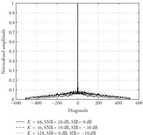
Figure7: Maximum normalized amplitude across the diagonals of the main block ofR−1
η .
As shown in Section 3.1, decoupling of the delay pa-rameters is based primarily on two conditions: matrix R−1
η
should possess a “heavy” diagonal, and matrixS(τ) a near-to-unitary structure. To verify the validity of these assump-tions, we plot in Figure 7 the maximum normalized am-plitude across the diagonals of the main block of R−1
η for
0 0.2 0.4 0.6 0.8 1
3 2 1 0 1 2 3
(a)
0 0.2 0.4 0.6 0.8 1
3 2 1 0 1 2 3
(b)
0 0.2 0.4 0.6 0.8 1
3 2 1 0 1 2 3
(c)
0 0.2 0.4 0.6 0.8 1
4 3 2 1 0 1 2 3 4
(d)
Figure8: Normalized amplitude across the diagonals ofSH(τ)S(τ) under test environments [22] with different delay spreadsτd: (a) vehicular channel A withτd=1.42Tc, (b) outdoor to indoor and pedestrian channel A withτd=0.17Tc, (c) indoor office channel B withτd=0.38Tc, and (d) outdoor to indoor and pedestrian channel B withτd=2.88Tc.
off-diagonal elements of lower amplitude. In all three cases, the off-diagonal elements of the matrix are one order of mag-nitude smaller than the diagonal ones. As far as the second condition is concerned, inFigure 8, we plot the normalized amplitude of SH(τ)S(τ) by projecting a 3D mesh plot on
the proper sideview. MatrixSH(τ)S(τ) was generated
accord-ing to the four test environment channel models with dif-ferent delay spreads, which are described inTable 1. Chan-nel (a) used in the previous simulations, as well as chanChan-nel (d), have a comparatively large delay spread, and thus ma-trix S(τ) is near-to-unitary. However channels (b) and (c) consist of closely spaced delays and near-to-unitarity condi-tion is violated. To investigate DPE’s robustness for closely spaced delays, we also simulated ITU indoor office chan-nel B described in Table 1. Since path delays were closely spaced, the algorithm fails to estimate correctly all paths. A single path located at an intermediate delay and one more path of negligible power are usually the estimates for two closely spaced paths. As shown inFigure 9, the performance of the proposed algorithm is not actually affected andhtot remains a good estimate of htot. The only possible draw-back could be a diversity order loss in case of a RAKE re-ceiver which naturally exploits multipath channel parame-ters.
5. CONCLUSIONS
10−3
Figure9: NMSE versus SNR forM=5 training symbols,K=64 active users, and SIR=0 dB for indoor office channel B.
APPENDIX
APPROXIMATE DIAGONALITY OF THE INVERSE MAI COVARIANCE MATRIX
In this appendix, we prove that the inverse of the MAI co-variance matrixRη =E[ηηH] has a high degree of diagonal
dominance. Starting withRη, we observe that due to the i.i.d.
property of the symbol sequences, the cross-user terms inside the expectation operator are equal to zero. Assuming, with-out loss of generality, that the desired user is user 1, the MAI covariance matrix can be expressed as follows:
Rη=
In the last equation,qkis partitioned into twoQN×1 blocks
corresponding to one symbol period each. Hence, according to (6), the contribution of userkcan be simplified as
Sk
user k and ∗denotes complex conjugation. The MQN ×
MQN covariance matrix of user k, defined as Rη,k =
E[(Sk(τk)ak)(Sk(τk)ak)H], can be partitioned intoM2blocks
of dimension QN ×QN, namely {Rη(i,,kj); i,j = 1· · ·M}. Since eachQN ×1 block ofSk(τk)ak depends only on two
consecutive symbols, the blocks R(ηi,,kj) lying in other than the main and the sub/super diagonals will vanish, yielding a block tridiagonal form forRη. Specifically, from (A.3), the
nonzero blocks ofRηcan be expressed as follows:
R(i,i)
whereσb2is the power of the input sequence. Due to the
or-thogonality of the spreading codes and the form of qk in
(A.3), vectorsq(kj), j =1, 2,k =2,. . .,K can be considered approximately orthogonal. Moreover, we may assume that the elements of these vectors are of the same order, which is quite reasonable according to (A.2). Thus, it is easily verified that the elements of the off-diagonal blocksR(ηi,i+1)andR(ηi,i−1)
are negligible compared to the main diagonal elements ofRη.
Hence, the MAI covariance matrixRη can be approximated
as a block diagonal matrix and the block that appears in its main diagonal is given by (A.4). Note that such an approx-imation has already been adopted intuitively in the relevant literature (see, e.g., [12,16]).
Moving a step further we show that the inverse MAI co-variance matrix can be approximated by a diagonal matrix. Indeed, by applying the matrix inversion lemma to (A.4), and taking into account the approximate orthogonality of the in-volved vectors, we end up with the following expression for the inverse of the diagonal blocks ofRη:
are of the same order, the summation term in (A.7) tends to aQN×QN zero matrix as the spreading sequence lengthN
and/or the oversampling factorQincrease. As a result, ma-trix [R(ηi,i)]−1and accordingly matrixR−η1tend to a diagonal
matrix with equal diagonal elements. In practice, matrixR−1
η
possesses a “heavy” main diagonal with almost equal energy elements, while its off-diagonal elements are of relatively lim-ited energy, as also verified in our simulations.
ACKNOWLEDGMENTS
was supported in part by the General Secretariat for Research and Technology under Grant PENED no. 03ED838 and in part by the Research Academic Computer Technology Insti-tute.
REFERENCES
[1] J. G. Proakis and M. Salehi,Communication Systems Engineer-ing, Prentice-Hall, Upper Saddle River, NJ, USA, 2002. [2] R. A. Iltis and L. Mailaender, “An adaptive multiuser detector
with joint amplitude and delay estimation,”IEEE Journal on Selected Areas in Communications, vol. 12, no. 5, pp. 774–785, 1994.
[3] U. Madhow, “Blind adaptive interference suppression for the near-far resistant acquisition and demodulation of direct-sequence CDMA signals,”IEEE Transactions on Signal Process-ing, vol. 45, no. 1, pp. 124–136, 1997.
[4] A. Logothetis and C. Carlemalm, “SAGE algorithms for mul-tipath detection and parameter estimation in asynchronous CDMA systems,” IEEE Transactions on Signal Processing, vol. 48, no. 11, pp. 3162–3174, 2000.
[5] M. Torlak and G. Xu, “Blind multiuser channel estimation in asynchronous CDMA systems,”IEEE Transactions on Signal Processing, vol. 45, no. 1, pp. 137–147, 1997.
[6] E. G. Strom, S. Parkvall, S. L. Miller, and B. E. Otter-sten, “Propagation delay estimation in asynchronous direct-sequence code-division multiple access systems,”IEEE Trans-actions on Communications, vol. 44, no. 1, pp. 84–93, 1996. [7] T. Ostman, S. Parkvall, and B. E. Ottersten, “An improved
MU-SIC algorithm for estimation of time delays in asynchronous DS-CDMA systems,”IEEE Transactions on Communications, vol. 47, no. 11, pp. 1628–1631, 1999.
[8] N. Petrochilos and A.-J. van der Veen, “Blind time delay esti-mation in asynchronous CDMA via subspace intersection and ESPRIT,” inProceedings of IEEE International Conference on Acoustics, Speech, and Signal Processing (ICASSP ’01), vol. 4, pp. 2217–2220, Salt Lake City, Utah, USA, May 2001. [9] Z. Ruifeng and T. Zhenhui, “ESPRIT-based delay estimators
for DS-CDMA systems,” inProceedings of IEEE International Conference on Communications (ICC ’00), vol. 3, pp. 1472– 1476, New Orleans, La, USA, June 2000.
[10] S. E. Bensley and B. Aazhang, “Subspace-based channel esti-mation for code division multiple access communication sys-tems,”IEEE Transactions on Communications, vol. 44, no. 8, pp. 1009–1020, 1996.
[11] S. E. Bensley and B. Aazhang, “Maximum-likelihood syn-chronization of a single user for code-division multiple-access communication systems,”IEEE Transactions on Communica-tions, vol. 46, no. 3, pp. 392–399, 1998.
[12] E. G. Strom and F. Malmsten, “A maximum likelihood ap-proach for estimating DS-CDMA multipath fading channels,” IEEE Journal on Selected Areas in Communications, vol. 18, no. 1, pp. 132–140, 2000.
[13] V. Tripathi, A. Montravadi, and V. V. Veeravalli, “Channel ac-quisition for wideband CDMA signals,”IEEE Journal on Se-lected Areas in Communications, vol. 18, no. 8, pp. 1483–1494, 2000.
[14] E. Ertin, U. Mitra, and S. Siwamogsatham, “Maximum-likelihood-based multipath channel estimation for code-division multiple-access systems,”IEEE Transactions on Com-munications, vol. 49, no. 2, pp. 290–302, 2001.
[15] E. Aktas and U. Mitra, “Single-user sparse channel acquisition in multiuser DS-CDMA systems,”IEEE Transactions on Com-munications, vol. 51, no. 4, pp. 682–693, 2003.
[16] A. A. D’Amico, U. Mengali, and M. Morelli, “Channel esti-mation for the uplink of a DS-CDMA system,”IEEE Transac-tions on Wireless CommunicaTransac-tions, vol. 2, no. 6, pp. 1132–1137, 2003.
[17] J. A. Fessler and A. O. Hero, “Space-alternating generalized expectation-maximization algorithm,” IEEE Transactions on Signal Processing, vol. 42, no. 10, pp. 2664–2677, 1994. [18] Universal Mobile Telecommunications System (UMTS),
“Spreading and modulation (FDD),” Technical Specification 3GPP 25.213, ETSI, Sophia-Antipolis, France, June 2005,
http://www.3gpp.org.
[19] ˚A. Bj¨orck, Numerical Methods for Least Squares Problems, chapter 9, SIAM, Philadelphia, Pa, USA, 1996.
[20] A. A. Rontogiannis, A. Marava, K. Berberidis, and J. Pali-cot, “Efficient multipath channel estimation using a semi-blind parametric technique,” inProceedings of IEEE Interna-tional Conference on Acoustics, Speech, and Signal Processing (ICASSP ’03), vol. 4, pp. 477–480, Hong Kong, China, April 2003.
[21] A. A. Rontogiannis, K. Berberidis, A. Marava, and J. Palicot, “Efficient semi-blind estimation of multipath channel param-eters via a delay decoupling optimization approach,”Signal Processing, vol. 85, no. 12, pp. 2394–2411, 2005.
[22] Universal Mobile Telecommunications System (UMTS), “Se-lection procedures for the choice of radio transmission tech-nologies of the UMTS,” Tech. Rep. 3GPP 101.112, ETSI, Sophia-Antipolis, France, April 1998.
Vassilis Kekatos was born in Athens, Greece, in 1978. He received the Diploma degree in computer engineering and infor-matics, and the Masters degree in signal processing from the University of Patras, Greece, in 2001 and 2003, respectively. He is currently pursuing the Ph.D. degree in sig-nal processing and communications at the University of Patras. He is a scholar at the Bodossaki Foundation. His research
inter-ests lie in the area of signal processing for communications. He is a Student Member of the IEEE and the Technical Chamber of Greece.
Athanasios A. Rontogiannis was born in Lefkada, Greece, in June 1968. He received the Diploma degree in electrical engineer-ing from the National Technical University of Athens, Greece, in 1991, the M.A.Sc. de-gree in electrical and computer engineering from the University of Victoria, Canada, in 1993, and the Ph.D. degree in communica-tions and signal processing from the Univer-sity of Athens, Greece, in 1997. From March
Kostas Berberidisreceived the Diploma de-gree in electrical engineering from DUTH, Greece, in 1985, and the Ph.D. degree in sig-nal processing and communications from the University of Patras, Greece, in 1990. From 1986 to 1990, he was a Research Assistant at the Research Adademic Com-puter Technology Institute (RACTI), Pa-tras, Greece, and a Teaching Assistant at the Computer Engineering and Informatics