Video Error Correction Using Steganography
David L. Robie
Center for Signal and Image Processing, Georgia Institute of Technology, Atlanta, GA 30332, USA Email: [email protected]
Russell M. Mersereau
Center for Signal and Image Processing, Georgia Institute of Technology, Atlanta, GA 30332, USA Email: [email protected]
Received 15 May 2001 and in revised form 14 November 2001
The transmission of any data is always subject to corruption due to errors, but video transmission, because of its real time nature must deal with these errors without retransmission of the corrupted data. The error can be handled using forward error correction in the encoder or error concealment techniques in the decoder. This MPEG-2 compliant codec uses data hiding to transmit error correction information and several error concealment techniques in the decoder. The decoder resynchronizes more quickly with fewer errors than traditional resynchronization techniques. It also allows for perfect recovery of differentially encoded DCT-DC components and motion vectors. This provides for a much higher quality picture in an error-prone environment while creating an almost imperceptible degradation of the picture in an error-free environment.
Keywords and phrases:error concealment, error correction, data hiding, steganography, MPEG-2.
1. INTRODUCTION
Video transmission requires the use of a compression al-gorithm in order to decrease the bandwidth to an afford-able value, and MPEG-2 is a widely accepted standard [1]. MPEG-2 achieves compression through the elimination of temporal, spatial, and statistical redundancies with the use of motion compensation, block quantization inside a discrete cosine transform (DCT), and Huffman run-length encoding. This compression, while reducing redundancies, creates a bit-stream that is much less fault tolerant. For example, single bit errors can cause a loss of synchronization that will be visible over an entire group of pictures (GOP). When considering the transmission of MPEG-2 video, one must be able to deal with the errors and the resulting loss of synchronization. The frailties of MPEG-2 have been addressed by both encoding and decoding schemes.
Many encoding schemes use data partitioning to enhance the robustness of the MPEG-2 stream. This can include ad-ditional resynchronization points by decreasing the length of slices or decreasing the number of frames in the GOP, but this comes at a cost of increased bit rate. An alternative is to partition the data in time, scale or SNR [2]. In any of the data partitioning modes, the multiple layers of data add resilience and are fully supported by MPEG-2; however, they increase the total bit rate. Other methods include sending additional side information to enhance the recovery of the decoder,
re-organizing the data to improve the resynchronization of the decoder or the use of forward error correction. An example of side information is the transmission of the concealment vec-tors, provided in the MPEG-2 standard, to recover lost data in I-frames. A system that reorganizes the data is described by Redmill [3] in which the macroblocks (MB) are aligned with the beginning of frames to enhance resynchronization in a packetized transmission system. The use of forward error correction such as Reed-Solomon codes require the packeti-zation of video and can be used for correction of bits errors or the recovery of lost packets [4]. Essentially, all encoder schemes introduce redundancies to enhance error recovery; however, all of these schemes result in an increase in the bit rate and many make the bit stream noncompliant.
Bit rate
Figure1: (a) Steganography can be viewed as a triangle of tradeoffs with the three sides being detectability, robustness, and bit rate. (b) A data hiding system will consist of a host signalXand a messageMthat is subject to a possible attack. The receiver must be able to decode or detect the hidden messageMˆ.
Resynchronization always results in the loss of at least one macroblock and temporal concealment fails in occluded re-gions and during scene changes; therefore, an effective spatial concealment algorithm is required in any complete error con-cealment scheme. Spatial concon-cealment based on interpolation works well in flat regions [8], but fails in textured regions or at edges. Directional interpolation and filtering performs much better in these areas [9, 10]. An excellent review of error con-cealment can be found in [11].
In this paper, we describe a codec that transmits redun-dant information to improve the resynchronization using steganography. This allows the decoder to remain fully com-pliant while still transmitting the error correction data. The basics of steganography are discussed in Section 2, its applica-tion to the codec is presented in Secapplica-tion 3 and the results are presented in Section 4. Section 5 contains conclusions and areas of further research.
2. STEGANOGRAPHY-DATA HIDING
Steganography is the art and science of data hiding. It can take many forms, has many applications, and has a rich and inter-esting history [12, 13]. Data hiding can be used for clandestine transmissions, closed captioning, indexing, or watermarking. This section provides an overview and interested readers are referred to [12, 14, 15].
Steganography can be viewed as a triangle of tradeoffs with the three sides being detectability, robustness, and bit rate (see Figure 1a) [16]. Detectability is the prize concern of clandestine transmission and is often used in conjunction with encryption. Robustness to all types of processing such as transformations, filtering, truncation, and scaling is the primary concern of the watermarking community. Finally, bit rate, or the maximum amount of data that can be trans-mitted, without serious degradation of the signal (a form of detection), is a concern for those interested in data tagging, indexing, and closed captions. Data hiding has been accom-plished using musical scores, invisible inks, word spacing, and
many other ingenious methods and its principals apply to transmission of all types; however, this discussion will be re-stricted to data hiding in digital signals and more specifically images and video.
A typical data hiding process (see Figure 1b) will begin with a signal,X, and a message,Mwith an option of using a key,Kfor encryption of the message. After insertingMinto X, the resultant signalXm is then transmitted. During this
transmission it may be subject to different attacks ranging from a noisy channel to intentional attempts to remove the message. Using the received signal,Xˆm, the receiver attempts
to recover the original message,M, or at least detect its pres-ence. To extract the message, the original signal,X, and a key, K, may or may not be required. First, the requirement to use the original signal to recover or detect the message is limited to the watermarking community where authenticity or proof of ownership is required; however, a key which is used in al-most all applications. The keys may be public or private and may be as simple as defining the location of the hidden data or it may be a cryptographic key to dissuade unauthorized access. Another common example of a key is the spreading sequence used in a spread spectrum data hiding model. Next, we will present several examples of data hiding in images and video. Due to commercial interest, most data hiding pub-lications are concerned with watermarking; however, many of the concepts remain the same in all applications of this technology.
Input video frame
Encode slicen
store MB size and differential final values
for allNslices Encode slicen+1; store MB size and differential values
stegano encode slicenMB size and differential values
Output video bitstream
(a) Encoder.
x(n1n2)
DCT X(k1k2) Q X(k 1k2)
X(k1k2) Encode stego
XS(k1k2) H/R/P
Output video stream IS
(b) Data hiding process.
Figure2: (a) The Steganocodec stores error-correction data in the following slice. (b) Information is stored in the DCT-AC coefficients.
modification of some or all pixels by imperceptible values. This minor modification in conjunction with spread spec-trum techniques is a popular method of watermarking [18]. Again spread spectrum techniques are robust but large chip rates can lead to very low bit rates. In the spatial domain, imperceptibility can be difficult to attain, therefore many re-searchers have attempted to use the frequency domain for data hiding.
In the frequency domain, the transform (e.g., FFT, DCT) of the image is taken, and again some or all of the coefficients are altered. Working in the frequency domain has several ad-vantages. First, perceptual models can be used to increase the imperceptibility of the hidden data. Also the energy spreading of the transform allows the data to be hidden across the entire image, and finally, when working with compressed images or video, variations in the frequency domain can be more easily embedded. The masking characteristics of the human visual system are exploited by Barni et al. [19] in their DCT domain system for watermarking. The ability to place a spatial water-mark in compressed images is demonstrated in [18] where the authors add a DCT version of their spatial watermark to JPEG compressed images. In this system, the watermark de-tection can be accomplished in either the frequency or spatial domain. Frequency domain techniques are extremely power-ful tools in steganography.
With reference to Figure 1a, this application of data hiding is most concerned with bit rate and detections. The larger the bit rate, the more error correcting information that can be transmitted, while detection is the form of degradation of the video quality. In this codec, the AC coefficients of the DCT are modified to transport error-correction information. Using a technique that toggles the least significant bit (LSB), the bitstream carries error-correction data, while introducing an almost imperceptible degradation of the video quality. The addition of error correction data in this method is preferred over User-Defined data as allowed by the MPEG-2 standard, because it distributes the recovery data over the entire file, vice placing it all in the sequence header with any other user data [20]. This distribution significantly decreases the possibility of losing both a slice and its error-correction data. In the
Input video bitstream
Decode each slice:n
If error, save all bits up to next start-of-slice for allNslices
For each error use stego data to resynchornize; if data not available, use Early Resynch technique
for all errors Output video frame
Figure3: During the decoding process all errors are stored until en-tire frame is decoded. Then errors are corrected/concealed using the stego data. If stego data is not available, the Early Resynchronization technique is used.
next section, the data hiding process of the Steganocodec will be described.
3. STEGANOCODEC
3.1. Encoder
Raw video is input to the encoder and in compliance with MPEG-2 standards, the frames are denoted as I-frames, P-frames, or B-frames based on the values of N (number of frames in GOP) andM(I/P frame distance). For each frame a slicen(see Figure 2a), is encoded and the following statistics are collected: the number of bits for each macroblock, the final DCT-DC coefficients for I-frames, final motion vectors for B-frames and P-B-frames, and the number of byte alignment bits at the conclusion of the slice. In the next slice,n+1, the data from the previous slice,Is, is hidden in the DCT coefficients
as described next.
Now consider the data hiding scheme shown in Figure 2b. Initially, the DCT of 8×8 blocks (image information in I-frames and error information in P/B-frames) is taken as shown in (1)
In I-frames, the DC component of the DCT is removed and encoded separately. Therefore it is not used for data hiding.
ˆ
Finally, the hidden dataIs, is inserted in the bitstream
as shown in (4). Since Is is binary data (i.e.Is = 0,1) it
acts to toggle the LSB’s of the nonzero DCT coefficients, ˆ
In the encoder, a global thresholding value,T, is used to determine which coefficients are encoded. This gives the en-coder the ability to influence the SNR of the video output without significantly changing the total bit rate. After some initial testing, we found that if all nonzero coefficients were used, image quality was maintained, with no change in the total bit rate. The final steps in Figure 2a are Huffman and run-length encoding, followed by packetization of the coeffi-cients into an MPEG-2 compliant bitstream.
A few additional notes concerning the encoder are in order. The probability of any MB being corrupted is not uniform. Within a slice, any error causing a loss of synchro-nization will corrupt that block and all blocks that follow. For example, consider a slice with 45 MB’s each containing the same number of bits. If an error occurs randomly in the slice, the probability that the first block is lost is 1/45 while the probability that the last block will be lost is1. With this in mind, and the fact that adjacent slices may be lost, it makes sense to carefully consider the order in which the data is transmitted. Therefore, the DCT-DC coefficients (I-frame) or motion vectors (P/B-frame) are transmitted first, followed by the byte alignment offsets and finally the size of the MB’s in reverse order (last MB in slice first). This scheme improves the probability that resynchronization data will be available even if adjacent slices are lost.
Finally, the last slice is unprotected. One possibility was to include this data in the first slice of the following frame, but for simplicity of decoding a single frame at a time, it was decided that the last slice could be unprotected. Also, errors in this slice are most easily concealed since this is rarely a region of interest. Next, the operation of the decoder will be presented.
3.2. Decoder
One of the key aspects of the steganography scheme is the full compliance of the decoder with the MPEG-2 standard. In the decoder, all the hidden data may be ignored by a coder incapable of using the data, while it is of full value to a de-coder that can use it. The dede-coder is the inverse of Figure 2b which includes retrieval of the hidden dataIs, inverse
Figure4: Original frame ofcameraman;256×256.
resynchronization (ER) scheme as described in [6]. Even when ER is used, any available information such as DCT-DC values or motion vectors, is used to enhance the recovery. The next section will discuss the error introduced by the data hiding algorithm.
3.3. Error analysis
One of the keys of steganography is to hide the data in the most imperceptible location. The technique used here takes full advantage by using the LSB of the quantized DCT coeffi-cients. In this section, a256×256version of thecameraman (Figure 4), will be used to illustrate the worst case effects of the data hiding algorithm. In this analysis, the image will be treated as an I-frame by the Steganocodec.
The first error introduced by the encoding system in Figure 2 is the quantization errorQ(equation (5)) which is
related to the frequency domain errorEQby (6). Note that the
quantization in (2), multiplication by1/Qin the frequency domain, relates to convolution in the time domain. The val-ues in the quantization matrix, Q(equation (3)), act as a low pass filter. Figure 5 is the compressed version of camera-man using the MPEG-2 quantization matrix and the mag-nitude of error,|Q|. The error has been scaled for better
presentation
Q=xn1, n2−xˆn1, n2, (5)
EQ=Xk1, k2−Xˆk1, k2. (6)
The next error,s, is the distortion of the DCT coefficients
with the hidden data (equations (7)). Recall from (4) thatIs
has no effect on DCT coefficients below the threshold, T, and will introduce a distortion only if the LSB the remaining coefficients differs fromIs(k1, k2)(approximately50%of the
time). For illustration, the maximum possible error, that is, every nonzero coefficient was changed, is included in Figure 6 which shows both the image and the magnitude of the error,
|s|. Again the error is scaled for viewing. The same scale is
used for both Figures 5 and 6 so meaningful comparisons can be made. Note the error is hidden in the areas with significant texture where it is most difficult to detect visually
s=xˆn1, n2−xˆsn1, n2,
Es=Xˆsk1, k2−Xˆk1, k2=Isk1, k2.
(7)
In the decoder, the inverse quantization, which involves multiplication byQ, will act as a high-pass filter of the signal
ˆ
Xs(Figure 7a). High-pass filtering of a signal with errors can
result in a significant degradation of image quality; however, because of the low-pass filtering in the encoder, most of the high frequency components are zero and unaffected. This ef-fect is illustrated in Figure 7b which is the FFT of the errors.
In this figure, the corners are low frequency with the center showing high frequency in both the horizontal and vertical directions; the figure is symmetrical since all the pixel val-ues are real. The image is gray scale with low valval-ues in black. The corners are all black indicating that the DCT-DC coeffi-cients are unaffected. The center is also dark indicating that very little of the error exists in the high frequency portions of the image. The lighter colors show the error is hidden in the middle frequency portion of the image where it is least perceptible. Two notes concerning this example. First, this is the maximum error; that is, all the nonzero DCT coefficients were changed; and second, this image is only256×256, much smaller than the typical MPEG-2 video format, which makes the errors appear more significant than in our video trials.
4. RESULTS
In this section, the results of the Steganocodec are presented in the following form. First the impact of the Steganocodec on the image quality in an error free environment will be shown. Next, with errors introduced into the bitstream, the results of different error concealment schemes will be contrasted with the Steganocodec. Finally, this section will conclude with ob-servations and comments about the data. Full color examples of these frames http://users.ece.gatech.edu/~robie/.
As discussed in Section 3, the Steganocodec’s ability to carry the additional information comes at a cost, that is, the quality of the picture is degraded; however, we hope to show that in an error-prone environment, the minor decrease in quality of all frames is made up for by the improved perfor-mance in error-correction and concealment. Presented below are results for13frames of three sequences:flower garden, cheer, andtennis. (N=6,M=3) encoded at 30 frames/s. with a bit rate of10MBits/s in a CCIR601 format (704×480). These sequences of 13frames allow the algorithm to work with a group of pictures (GOP) following a scene change (Frame0) and another without the scene change.
(a) Compressed. (b) Magnitude of error,|Q|.
Figure5: (a) Compressed version ofcameramanusing the MPEG-2 quantization matrix. (b) Magnitude of error,|Q|, scaled for viewing.
(a) Compressed with hidden data. (b) Magnitude of error|s|.
Figure6: (a) Compressed version ofcameramanwith the maximum data hiding error. (b) Magnitude of maximum possible error,|s|, scaled for viewing.
The entire capacity of the channel was not used and the fifth column shows the number of useful bits transmitted with the percent of the channel capacity used in the next column. The last column represents the PSNR of the luminance signal as compared to the same sequence coded without any stego data. Subjectively, using a high quality21TV monitor, we found that PSNR of15presented a snowy picture; when the PSNR was25, the error was barely noticeable, and a PSNR of about 35made the errors undetectable. In conclusion, the loss of quality for the three sequences was minimal. Table 2 shows the PSNR for13frames of theflower gardensequence us-ing several different error-correction schemes. The bitstream was encapsulated in an AAL5 type packet and packets were lost with uniform probability with a loss rate of 10−4. The
first column is simple temporal error concealment, using the information from the previous frame with no correction for motion. The second column uses an early resynchronization (ER) scheme similar to [6] and last column is error-correction and concealment using the Steganocodec. Examples of the ER
and Steganocodec sequence are shown in Figures 8 and 9. The improvements of the Steganocodec over the other schemes is the result of two significant issues. First is the importance of the DCT-DC components. In the ER scheme, these are estimated from the surrounding macroblocks while in the Steganocodec, they are computed from the end values as de-scribed in Section 3. Second, in early resynchronization, the maximum number of macroblocks is not always decoded cor-rectly; the first macroblocks frequently contain errors that are not detected by the decoder. Both of these issues, although ev-ident in PSNR are much more an issue in subjective viewing since both produce noticeable artifacts.
(a) Frequency response. (b) FFT of error,|s|.
Figure7: (a) The frequency response of the inverse quantization matrix,Q. (b) Two-dimensional FFT of the errors. Low frequencies are in the corners, high frequencies in the center of the image. Black corresponds to low values; white to high. Note the error is located in the middle frequencies in both horizontal and vertical directions.
Table1: Stegano characteristics for13frames offlower garden,cheer, andtable tennis.
No stegano W/stegano Channel cap Data Xfer Used cap Y PSNR
(Bytes) (Bytes) (Bits) (Bits) (%) (dB)
flower 545585 524484 526994 395144 75% 28.74
cheer 546728 546829 525118 402621 77% 32.94
tennis 542158 544453 515725 379805 74% 36.74
Table2: PSNR for13frames offlower gardenusing temporal
error concealment, ER, and the Steganocodec.
Frame Temporal ER Stegano
0 10.33 18.92 22.07 1 10.93 14.85 22.20 2 10.05 19.54 22.10 3 10.09 19.90 23.19 4 10.47 21.12 23.42 5 10.25 22.42 24.88 6 10.25 25.11 28.29 7 10.41 22.38 24.91 8 10.19 24.30 26.42 9 9.87 23.13 26.66 10 10.19 24.67 26.19 11 10.24 25.58 26.58 12 10.32 27.60 27.95
Finally, multiple errors in a single slice were not considered because both schemes resort to a temporal concealment of the lost area. This would have no impact on PSNR differences, since both decoders yield the same results.
Again, using data from theflower garden sequence,
Table 3 illustrates the performance of this codec. Note the rows define the type of frame, I, P, or B, with the first column indicating the number of each frame type and the total and average number of errors for each. The next column indicates how often the error-correction data was recovered and used. The last two columns pertain to the loss of adjacent slices. The first of these two indicates the number of adjacent slices lost in each frame type and the last is the percentage of times error-correction data was available for recovery after the loss of the following row.
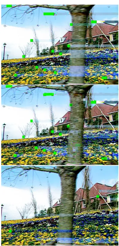
Figure8: Three frames using Early Resynchronization only. (Note: to highlight the location of the errors, no spatial concealment used.) Top is the first I-frame of the sequence. Middle is the second frame (B-frame). Bottom is the next I-frame (seventh frame in this se-quence).
the first portion of the slice, again decreasing the probability of loss. In P-frames, the performance of the error-correction data is again excellent; the two cases where error-correction data was unavailable was the result of adjacent slices being lost. In B-frames, the performance falls because the low bit rate limits the bandwidth available for the transmission of error-correction data. In this simple panning sequence, the B-frames are encoded very efficiently with numerous skipped MB’s. This decrease in the bandwith makes the recovery of stego data with adjacent slice losses virtually impossible. In fact, in a small percentage of the slices, there was not enough bandwidth to send all stego data, which made the recovery of long slice errors not possible. This is not a serious limitation, because the most important frames to protect are I-frames and P-frames since they impact more than one frame;
how-Figure9: The results of the Steganocodec, with same error sequence as before. Again no spatial error concealment. Top is first frame (I-frame) of sequence. Middle is second (B-(I-frame), and bottom is next I-frame in sequence. Note the importance of recovering the DCT-DC values.
ever, errors in the B-frames can be more easily tolerated since these errors do not propagate. One final note that is not ad-dressed in this table is that even if all the concealment data are not present, the differentially encoded MV’s and DCT-DC coefficients were used which significantly decreases visual ar-tifacts.
Table3: Error recovery statistic for theflower gardensequence.
Frame Number Total Average Stegano Adjacent Stegano
type frames errors errors data slices data
I 3 30 10.0 97% 8 100%
P 2 15 7.5 86% 4 50%
B 8 39 4.9 79% 5 40%
Total 13 84 NA 87% 15 71%
Table4: PSNR for13frames offlower garden,cheer, and
ten-nis.
Temporal Resynch Stegano
flower 10.28 22.27 24.99
cheer 13.34 18.82 18.98
tennis 15.19 24.13 28.07
was used in an effort to highlight the location of the errors. In the first frame of Figures 8 and 9, the most noticeable fac-tor is the importance of accurately recovering the DCT-DC components. In the second frame of each figure the propa-gation of the errors is evident. The final frame of each fig-ure, the excellent performance of the stegocodec is evident in the fact that the image is almost error free with nine er-rors. In the last frame of Figure 8, several artifacts are no-ticeable on the roofs (slices 11, 13, and 14 of 30) of the houses, and the poor recovery of the DCT-DC components (slices 21 and 27) is shown in the shade banding across the trunk of the tree. Overall, the improvements in both PSNR and subjective viewing are easy to recognize. These improve-ments are even more evident in full color images that may be seen at http://www.ece.gatech.edu/~robie. Although space does not allow, all the sequences in Table 4, show similar improvements in PSNR for the cheer and table tennis sequences.
5. CONCLUSIONS
This paper presents the Steganocodec, which uses steganog-raphy to transfer resynchronization data from the encoder to the decoder. This hidden information comes at an imper-ceptible decrease in picture quality while not influencing the total bit rate. In all cases, the decoder performed better than early resynchronization.
Topics for further research in this area include the possi-bility of using a variable rate for the stego encoder. This may decrease the influence the decoder has on the frames with no errors. Also, adapting the quantity of error-correction infor-mation, based on the quality of service would allow the best possible picture given for a given channel.
In closing, the Steganocodec provides a marked improve-ment over the existing methods of error-correction and concealment while remaining compatible with the MPEG-2 standard.
REFERENCES
[1] “Generic coding of moving pictures and associated audio infor-mation: video,” ISO/IEC 13812: Draft International Standard, November 1994.
[2] R. Aravind, M. R. Civanlar, and A. R. Reibman, “Packet loss resilience of MPEG-2 scalable video coding algorithms,”IEEE Trans. Circuits and Systems for Video Technology, vol. 6, pp. 426–435, October 1996.
[3] D. W. Redmill and N. G. Kingsbury, “The EREC: an error-resilient technique for coding variable-length blocks of data,” IEEE Trans. Image Processing, vol. 5, no. 4, pp. 565–574, 1996. [4] S. H. Lee, P. J. Lee, and R. Ansari, “Cell loss detection and
recov-ery in variable rate video,” inProc. 3rd International Workshop on Packtized Video, Morristown, NJ, USA, March 1990. [5] S. Aign, “Error concealment, early resynchronization, and
iter-ative decoding for MPEG-2,” inProc. IEEE International Con-ference on Communications, vol. 3, pp. 1654–1658, Montreal, Canada, June 1997.
[6] C. Le Buhan, “Software-embedded data retrieval and er-ror concealment schemes for MPEG-2 video sequences,” in Digital Video Compression: Algorithms and Technologies, vol. 2668 ofProceedings SPIE, pp. 384–391, San Jose, Calif, USA, 31 January–2 February 1996.
[7] C. L. Fernandez, A. Brasso, and J. Hubaux, “Error concealment and early resynchronization techniques for MPEG-2 video streams damaged by transmission over ATM networks,” in Digital Video Compression: Algorithms and Technologies, vol. 2668 ofProceedings SPIE, pp. 372–383, San Jose, Calif, USA, 31 January–2 February 1996.
[8] S. Aign and K. Fazel, “Temporal and spatial error concealment techniques for hierarchial MPEG-2 video codec,” inIEEE Inter-national Conference on Communications, vol. 3, pp. 1778–1783, Seattle, Wash, USA, June 1995.
[9] W. Kwok and H. Sun, “Multi-directional interpolation for spatial error concealment,” IEEE Transactions on Consumer Electronics, vol. 39, no. 3, pp. 455–460, 1993.
[10] D. Robie and R. Mersereau, “The use of Hough transforms in spatial error concealment,” inProc. IEEE Int. Conf. Acous-tics, Speech, Signal Processing, vol. 4, pp. 2131–2134, Istanbul, Turkey, June 2000.
[11] Y. Wang and Q.-F. Zhu, “Error control and concealment for video communications: a review,”Proceedings of the IEEE, vol. 86, no. 5, pp. 974–977, 1998.
[12] F. A. P. Petitcolas, R. J. Anderson, and M. G. Kuhn,“Information hiding—a survey,” Proceedings of the IEEE, vol. 87, no. 7, pp. 1062–1078, 1999.
[13] R. J. Anderson and F. A. P. Petitcolas, “On the limits of steganog-raphy,”IEEE Journal on Selected Areas in Communications, vol. 16, no. 4, pp. 474–481, 1998.
digital image and video data,”IEEE Signal Processing, vol. 17, no. 5, pp. 20–46, 2000.
[16] J. R. Smith and B. O. Comiskey, “Modulation and information hiding in images,” inProc. 1st Information Hiding Workshop, vol. 1174 ofLecture Notes in Computer Science, Springer-Verlag, Cambridge, UK, May 1996.
[17] W. Bender, D. Gruhl, N. Morimoto, and A. Lu, “Techniques for data hiding,” IBM Systems Journal, vol. 35, no. 3-4, pp. 313–336, 1996.
[18] F. Hartung and B. Girod, “Watermarking of compressed and uncompressed video,”Signal Processing, vol. 66, no. 3, pp. 283– 301, 1998.
[19] M. Barni, F. Bartolini, V. Cappellini, and A. Piva, “A DCT-domain system for robust image watermarking,” Signal Pro-cessing, vol. 66, no. 3, pp. 257–372, 1998.
[20] B. G. Haskel, A. Puri, and A. N. Netravali, Digital Video: An Intorduction to MPEG-2, Chapman and Hall, New York, USA, 1997.
David L. Robiereceived his B.S. and M.S. in electrical engineering from the Pennsylvania State University, State College, Pa, USA in 1981 and 1985, respectively. He is presently pursuing a Ph.D. in electrical engineering at the Georgia Institute of Technology, At-lanta, Ga, USA. His research interests in-clude video compression, error correction and concealment, and data hiding. He also works for the Air Force Research Lab in Day-ton, Ohio, in hyper-spectral image processing.
Russell M. Mersereaureceived his B.S. and M.S. degrees in 1969 and the Sc.D. in 1973 from the Massachusetts Institute of Tech-nology. He joined the School of Electrical and Computer Engineering at the Georgia Institute of Technology in 1975. His current research interests are in the development of algorithms for the enhancement, modeling, and coding of computerized images, synthe-sis aperture radar, and computer vision. In