Suspended Rectangular Slit Loaded
Microstrip Antenna
Suryakanth Nirate1, M. S. Lakshetty2, R.M.Vani3, P.V.Hunagund4
Research Scholar, Dept. of Applied Electronics, Gulbarga University, Kalaburagi, Karnataka, India1
Guest Faculty, Dept. of Applied Electronics, Gulbarga University, Kalaburagi, Karnataka, India2
Professor & Head, Univ. Sci. Inst. Centre (USIC), Gulbarga University, Kalaburagi, Karnataka, India3
Professor & Chairman, Dept. of Applied Electronics, Gulbarga University, Kalaburagi, Karnataka, India4
ABSTRACT: This paper presents designing of line fed and Slit Loaded Microstrip Antenna (MSA). The antenna is designed to overcome the disadvantage of MSA i.e. narrow bandwidth. Microstrip line fed antenna provides wide bandwidth. It’s working frequency range 8.42-13.33GHz and 14.31-16GHz with return loss of less than -10 dB. Hence bandwidth enhancement can be obtained by Suspended Rectangular Slit Loaded Microstrip Antenna. Obtained bandwidth is 45.17 % & 11.15% respectively with respect to center frequency. The substrate material of FR-4 with relative permittivity 4.4 and loss tangent of 0.0245 is used in this proposed antenna. The return loss and radiation pattern have been measured by using Vector Network Analyzer.
KEYWORDS: Suspended Microstrip Antenna, Microstripline Feed, Slits, Rectangular Patch Antenna.
I. INTRODUCTION
Antenna is a transducer designed to transmit as well as receive electromagnetic waves. Also the antenna is transitional structure between free space and a guiding device. An MSA in its simplest form consists of a radiating patch on one side of a dielectric substrate and a ground plane on the other side. With enormous growth in wireless communications technology from past few years, design of compact, low profile, and wideband antennas for wireless communications is a major challenge for antenna design researchers [1]. Microstrip patch antennas are commonly used in wireless communications like Bluetooth, Wi-Fi, WLAN, WiMax applications owing to their attractive features such as small size and hence conformal nature, easy to feed and design, low fabrication cost, robust nature, light in weight, and easily integrate with monolithic microwave integrated circuits (MMIC) [2]. However, standard microstrip patch antennas cannot satisfy the bandwidth requirements for most wireless communication systems because of their narrow bandwidth. This inherent drawback poses design challenge for the microstrip antenna designer to meet the requirements of wireless communications [3, 4]. Over the years various well-known designs have been investigated to improve the bandwidth of the microstrip antennas including the use of thicker substrates [5], use of different shapes of patch [6, 7, 8], use of low dielectric substrate, use of various impedance matching and feeding techniques like microstrip line or coaxial feeding [9], use of stacked microstrip patches [10] and parasitically coupled or gap-coupled patches [11], and the use of shorting pins [12].
II. ANTENNA GEOMETRY AND DESIGN
In the proposed design, the antenna has been designed for 6 GHz and is fed using microstrip line feed. The length and width of the rectangular patch are Land Wrespectively. The feed arrangement consists of quarter wave transformer of length Ltand width Wtwhich is connected as a matching network between the patch and the microstripline feed of
length Lf50 and width Wf50. At the very first the antenna is designed in a suspended mode. In the suspended
rectangular microstrip antenna configuration, two layers of FR4 substrates (εr = 4.4, h = 1.6 mm and tan δ=0.0245)
separated by air gap () is shown in Fig. 1.
Fig.2. shows the top view geometry of Suspended Rectangular Slit Loaded MSA. On right and left si de of the radiating edges of the patch, rectangular slit is inserted. The dimensions of the slit is a1=a2=λ/7.57 mm, b1=b2=1 mm , c=4.19 mm and d=5.19 mm respectively.
b2 a1 b1 a2 c d Lt Wt
Lf50
Wf50
Fig.2 Geometry of Suspended Rectangular Slit Loaded MSA
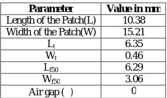
Table.1 shows the design parameters of the proposed antenna.
Table 1: Design Parameters of the Antenna
Parameter Value in mm
Length of the Patch(L) 10.38 Width of the Patch(W) 15.21
Lt 6.35
Wt 0.46
Lf50 6.29
Wf50 3.06
III.RESULTSANDDISCUSSION
The antenna bandwidth over return loss less than -10 dB is measured experimentally on Vector Network Analyzer (Rohde & Schwarz, Germany make ZVK model 1127.8651.60). The variation of return loss verses frequency of Suspended Rectangular Slit Loaded MSA is as shown in Fig. 3.
4 .0 G 6 .0 G 8.0G 10 .0 G 12 .0 G 1 4 .0 G 16 .0 G -2 0
-1 5 -1 0 -5 0
R
e
tu
rn
lo
s
s
(d
B
)
F re q u e n cy (H z)
P ro p o se d a n te n n a
Fig. 3 Variation of Return loss Verses Frequency of Suspended Rectangular Slit Loaded MSA.
It is observed from the graph that the antenna operates for two bands of frequencies i.e., Band1 (BW1) and Band2
(BW2). The first resonant mode f1 is at 8.42 GHz and the second resonant mode f2 is at 14.96 GHz
Table 2: Experimental results of SRMSARS
Antenna name
Resonant Frequency
(GHz)
Return Loss (dB) Bandwidth (%)
Band1 Band2 BW1 BW2
Table.2 shows the experimental results ofproposed antenna. The proposed antenna resonates at 14.96 GHz. From the Table.2 it is observed that bandwidth of the BW1 is more compare to BW2.
Fig.4 Input impedance plot of proposed Antenna
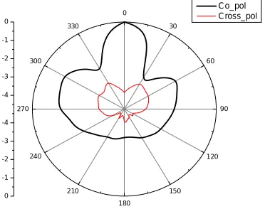
Fig.4 shows the Input impedance plot of proposed antenna. It shows good input impedance. Fig .5 shows radiation pattern for the proposed antenna.
-4 -3 -2 -1 0
0
30
60
90
120
150 180
210 240 270
300 330
-4 -3 -2 -1 0
Co_pol Cross_pol
Fig .5 Radiation pattern of proposed antenna
From the above figure it is clear that antenna shows good co-polarization with minimum cross-polarization.
0 0.2 0.5 1 2 5 10
-5
-2
-1 -0.5
0.5
1
2
5
CH1 1 U
START 3 GHz STOP 16 GHz
FIL 1k 1k FIL 1k 1k CAL
S11
1
1: 55.64 -j9.691
14.96 GHz
IV.CONCLUSION
In this paper a Suspended Rectangular Slit Loaded Microstrip Antenna is presented. From the detailed experimental study, it is concluded that, antenna operates for two bands of frequencies in the range of 8 GHz to 16 GHz. With these features the proposed antennas may find application in microwave communication systems operating in the frequency range of 8 to 16 GHz. Antenna gives better bandwidth of 45.17 % and 11.15 % respectively. Also the antenna shows good input impedance of 55.64-j9.61.
REFERENCES
1. S. L. S. Yang, A. A. Kishk and K. F. Lee, “Frequency reconfigurable U-slot microstrip patch antenna”, IEEE Antennas and Wireless Propagation Letters, vol. 7, (2008), pp. 127-129.
2. K.-L. Wong, “Compact and Broadband Microstrip Antennas”, Wiley and Sons, Inc., New York, vol. 1, (2002), pp. 12-15.
3. Y. P. Zhang and J. J. Wang, “Theory and analysis of differentially-driven microstrip antennas”, IEEE Transactions on Antennas and Propagation, vol. 54, (2006), pp. 1092-1099.
4. D. M. Pozar and D. H. Schaubert, “Microstrip Antennas: The Analysis and Design of Microstrip Antennas and Arrays”, IEEE Press, New York, (1995).
5. J. R. James and P. S. Hall, “Handbook of Microstrip Antennas”, Peter Peregronic Ltd., London, (1989).
6. Y. Ge, K. P. Esselle and T. S. Bird, “E-Shaped patch antennas for high-speed wireless networks”, IEEE Transaction on Antennas and Propagation, vol. 52, (2004) December 12, pp. 3213–9.
7. A. Ali, L. Neyestanak, et al., “W-shaped enhanced bandwidth patch antenna for wireless communication”, Wireless Pers. Communication, vol. 43, (2007), pp. 1257-1265.
8. M. Abbaspour and H. R. Hassani, “Wideband star-shaped microstrip patch antenna”, Progress in Electromagnetics Research Letters, vol. 1, (2008), pp. 61-68.
9. M. M. Matin, B. S. Sharif and C. C. Tsimenidis, “Probe fed stacked patch antenna for wideband applications”, IEEE Transactions on Antennas and Propagation, vol. 55, no. 8, (2007), pp. 385-2388.
10. J. A. Ansari and R. B. Ram, “Broadband stacked U-slot microstrip patch antenna”, Progress In Electromagnetics Research Letters, vol. 4, (2008), pp. 17-24.
11. J. A. Ansari, R. B. Ram and P. Singh, “Analysis of a gap-coupled stacked annular ring microstrip antenna”, Progress In Electromagnetic Research B, vol. 4, (2008), pp. 147-158.
12. J. A. Ansari, P. Singh, N. P. Yadav and B. R. Vishvakarma, “Analysis of shorting pin loaded half disk patch antenna for wideband operation”, Progress In Electromagnetic Research C, vol. 6, (2009), pp. 179-192.
13. Deschamps, G. A., ‘‘Microstrip Microwave Antennas’’, Proc. 3rd USAF Symposium on Antennas, 1953. 14 Munson, R. E., ‘‘Single Slot Cavity Antennas Assembly,’’ U.S. Patent No. 3713162, January 23, 1973.
15. Munson, R. E., ‘‘Conformal Microstrip Antennas and Microstrip Phased Arrays,’’IEEE Trans. Antennas Propagation, Vol. AP-22, 1974, pp. 74–78.
16. Howell, J. Q., ‘‘Microstrip Antennas,’’ IEEE Trans. Antennas Propagation, Vol. AP-23, January 1975, pp. 90–93. 17 Bahl, I. J., and P. Bhartia, Microstrip Antennas, Dedham, MA: Artech House, 1980.
18. Carver, K. R., and J. W. Mink, ‘‘Microstrip Antenna Technology,’’ IEEE Trans.Antennas Propagation, Vol. AP-29, January 1981, pp. 2–24.
19. Mailloux, R. J., et al., ‘‘Microstrip Array Technology,’’ IEEE Trans. Antennas Propagation,Vol. AP-29, January 1981, pp. 25–37.
20. James, J. R., et al., ‘‘Some Recent Development in Microstrip Antenna Design,’’IEEE Trans. Antennas Propagation, Vol. AP-29, January 1981, pp. 124–128.
21. James, J. R., and P. S. Hall, Handbook of Microstrip Antennas, Vol. 1, London: Peter,Peregrinus Ltd., 1989.
22. Shushant Jain, et al Bandwidth Enhanced E- Shaped Microstrip Antenna With Pair Of Wide Slits”, International Journal of Computer and Electronics Research, Volume 1, Issue 4, December 2012,pp.187-191.
23 Girish Kumar and K.P.Ray, “Broadband Microstrip Antennas”, Artech House London. ISBN 1-58053-244-6.
24. J. Chandrasekhar Rao et al., “H-U-E Shaped Slotted Microstrip Antenna for Bandwidth Enhancement”,Vol.7, No.4 (2014), pp.141-148
BIOGRAPHY
Dr. M. S. Lakshetty received his M.Sc., M.Phil. and Ph.D. degree in Applied Electronics from Gulbarga University, Kalaburagi in the year 2005, 2007 and 2011 respectively. He is working as Guest Faculty in Dept. of Applied Electronics, Gulbarga University, Kalaburagi. He has more than 80 publications in reputed International/National Journals and in conference and symposia. His Research interest includes microstrip antenna, arrays and dielectric resonator antenna.
Dr.Vani. R.M. received her B.E. in Electrical and Electronics from the B.I.ET., Davanagere, Karnataka, and M.Tech in Industrial Electronics from S.J.C.E., Mysore. She has received her Ph.D in Applied Electronics from Gulbarga University, Kalaburagi, in year 2005. She is working as Professor and Head, University Science Instrumentation Center, Kalaburagi, since 1995. She has more than 85 research publications in National and International reputed journals and Conference proceedings. She presented many research papers in India & Abroad. She has conducted several courses, workshops for the benefit of faculties and field engineers. Her areas of interest are microwave antennas, PC based Instrumentation, Embedded controllers and wireless communication. She has one UGC major research project to her credit.