Steerable filters generated with the hypercomplex dual-tree
wavelet transform
WEDEKIND, J., AMAVASAI, B. P. and DUTTON, K.
Available from Sheffield Hallam University Research Archive (SHURA) at:
http://shura.shu.ac.uk/953/
This document is the author deposited version. You are advised to consult the
publisher's version if you wish to cite from it.
Published version
WEDEKIND, J., AMAVASAI, B. P. and DUTTON, K. (2007). Steerable filters
generated with the hypercomplex dual-tree wavelet transform. In: IEEE International
Conference on Signal Processing and Communications (ICSPC 2007), Dubai,
United Arab Emirates, 24-27 November 2007. IEEE, 1291-1294.
Copyright and re-use policy
See
http://shura.shu.ac.uk/information.html
STEERABLE FILTERS GENERATED WITH THE HYPERCOMPLEX DUAL-TREE WAVELET
TRANSFORM
J. Wedekind, B. Amavasai, K. Dutton
MMVL, Materials and Engineering Research Institute Sheffield Hallam University,
Pond Street, Sheffield S1 1WB
{J.Wedekind,B.P.Amavasai,K.Dutton}@shu.ac.uk
ABSTRACT
The use of wavelets in the image processing domain is still in its infancy, and largely associated with image compression. With the advent of the dual-tree hypercomplex wavelet transform (D-HWT) and its improved shift invariance and directional selec-tivity, applications in other areas of image processing are more conceivable. This paper discusses the problems and solutions in developing the DHWT and its inverse. It also offers a practical implementation of the algorithms involved. The aim of this work is to apply the DHWT in machine vision.
Tentative work on a possible new way of feature extraction is presented. The paper shows that 2-D hypercomplex basis wave-lets can be used to generate steerable filters which allow rotation as well as translation.
Index Terms— Image Processing, Wavelet transforms,
Fea-ture extraction, Algorithms, Linear systems
1. INTRODUCTION
Wavelets are of significant interest in signal processing. However in contrast to the discrete Fourier transform the discrete wavelet transform is not shift invariant. In the area of image processing this has restricted the use of the wavelet transform to areas such as image compression where shift invariance is not a require-ment. Recent research in wavelet signal processing however has resulted in the dual-tree complex wavelet transform[1] which of-fers approximate shift invariance and amplitude-phase analysis.
Analogical to 1-D signals requiring a pair of complex wave-lets, 2-D signals require a quadruple of hypercomplex wavelets for analysis[2]. This analogy extends to higher dimensions as well, and the hypercomplex wavelet transform can for example be used to filter 3-D data[3]. The hypercomplex wavelet trans-form has already been used for optic flow estimation, texture seg-mentation, and feature extraction.
This paper outlines a complete implementation of Selesnick’s biorthogonal wavelet filter design technique and the dual-tree hy-percomplex wavelet transform. The dual-tree hyhy-percomplex wa-velet is then used to generate three steerable filters which allow rotation as well as translation.
2. STATE OF THE ART
An outline of Selesnick’s filter design technique for designing biorthogonal wavelets[4] is hereby given. For a more detailed
This project was supported by the Nanorobotics EPSRC Basic Technology grant GR/S85696/01
introduction to the dual-tree wavelet transform see Selesnick’s joint publication with Kingsbury[1].
2 2
H
0(
z
)
H
1(
z
)
2 2H
0(
z
)
H
1(
z
)
recursion
G
0(
z
)
G
1(
z
)
2 2
G
0(
z
)
G
1(
z
)
2 2 [image:2.595.310.517.299.410.2]recursion
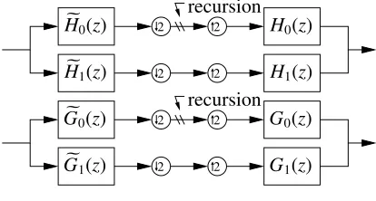
Figure 1. Biorthogonal wavelet filters
Ifh0, h1,h0, andh1 are odd-length real-valued filters and
H0,H1,H0, andH1their Z-transforms, the perfect reconstruction
condition for the first filter bank in figure 1 is
H0(z)H0(−z)+H1(z)H1(−z)=0 and
H0(z)H0(z)+H1(z)H1(z)=2
(1)
By lettingH1(z)=H0(−z) andH1(z)=−H0(−z) the first part of
equation (1) is satisfied. The biorthogonality is established by
H0(z)=F(z)D(z), H0(z)=F(z)D(z−1)z1−L,
G0(z)=F(z)D(z−1)z1−L, G0(z)=F(z)D(z)
withF(z)=Q(z) (1+z−1)KandF(z)=Q(z) (1+z−1)K
(2)
whereKandKare the numbers of desired vanishing moments.
Dis a Thiran filter[4] to approximate a half sample delay
d(n)=
L−1
n
(−1)n
n−1
k=0
τ−L+1+k
τ+1+k ,hereτ=0.5 (3)
To also fulfil the second part of equation (1) both filter-pairs have to meet the following condition
H0(z)H0(z)=G0(z)G0(z)=Q(z)Q(z)S(z)=2
whereS(z)≔(1+z−1)K+KD(z)D(z−1)z1−L
(4)
Solving the following equation system yieldsR(z)≔Q(z)Q(z).
⎛ ⎜⎜⎜⎜ ⎜⎜⎜⎜ ⎜⎜⎜⎜ ⎜⎜⎜⎜ ⎜⎜⎜⎜ ⎜⎝
sN 0 · · ·
sN−2 sN−1 sN 0 · · ·
..
. ... ... ... ...
· · · 0 s1 s2 s3 · · · 0 s1 ⎞ ⎟⎟⎟⎟ ⎟⎟⎟⎟ ⎟⎟⎟⎟ ⎟⎟⎟⎟ ⎟⎟⎟⎟ ⎟⎠ ⎛ ⎜⎜⎜⎜ ⎜⎜⎜⎜ ⎜⎜⎜⎜ ⎜⎜⎜⎜ ⎜⎜⎜⎜ ⎜⎝
r1
r2
.. . rN−1
rN ⎞ ⎟⎟⎟⎟ ⎟⎟⎟⎟ ⎟⎟⎟⎟ ⎟⎟⎟⎟ ⎟⎟⎟⎟ ⎟⎠
=
⎛ ⎜⎜⎜⎜ ⎜⎜⎜⎜ ⎜⎜⎜⎜ ⎜⎜⎜⎜ ⎜⎜⎜⎜ ⎜⎜⎜⎜ ⎜⎝
.. . 0 1 0 .. .
⎞ ⎟⎟⎟⎟ ⎟⎟⎟⎟ ⎟⎟⎟⎟ ⎟⎟⎟⎟ ⎟⎟⎟⎟ ⎟⎟⎟⎟ ⎟⎠
whereN=K+K+2L−1,andNis odd
(5)
Note thatRis symmetric (R(z) =R(z−1)zN−1) because of
equa-tion (5).
3. SPECTRAL FACTORISATION WITH LAGUERRE
To determine a pair of spectral factorsQandQ, each root ofRis assigned to either become a root ofQor a root ofQ. SinceRis symmetric and odd-length, for every rootoithere is a related root
at 1/oi. AsRalso is real-valued, each complex root therefore has
related roots ato∗
i, 1/oi, and 1/o∗i. The roots ofR(z)zN
−1can be
determined using Laguerre’s iterative method[5] and polynomial division. Instead of reducing the polynomial by only a single root, first polynomial division with (1−oi) (1−oi∗) (1−1/oi) (1−
1/o∗
i) is attempted. If the error is too large, the occurrence of a
pair of real roots is assumed and reduction with (1−oi) (1−1/oi) is
performed. This approach allows to safely choose the roots in the next step. Polynomial division without remainders is formulated as a least squares problem as shown in [6].
AsQandQneed to be symmetric and real-valued, each root of a group of two or four related roots must be assigned to the same spectral factor. Furthermore the difference in size ofQand
Qshould be minimal. Applying these criteria can still leave a list of choices. At least for larger filters however there does not seem to be much difference between these.
After choosing a spectral factorisation the filters can be com-puted according to equation (2). Finally the filters are normali-sed. Note that equation (5) requiresr1 = 0 andrN = 0. This
is solved by performing spectral factorisation forr2zN−2+r3+
zN−3+. . .+r
N−1and later extendingQ(z) with a zero coefficient
at the beginning and the end.
4. 2-D HYPERCOMPLEX WAVELET TRANSFORM
The two-dimensional wavelet tree shown in [7], which already uses four-element vectors, can be represented using hypercom-plex numbers as follows. First the real-valued image is multi-plied with (1+i+j+k) so that all four components of the resulting hypercomplex number equal each other.
prepare(X)(z)≔X(z) (1+i+j+k) (6)
1,i,j,k∈HCA2are the units of the commutative hypercomplex
algebraHCA2[2]. The layers of the wavelet pyramid are
com-puted by recursively applying the following function to the lower frequency band
decompose(1)a,b(W)(z)≔
[↓z22]
[↓z12]
R
W(z)Ha(z1) Hb(z2)
+
[↓z22]
[↓z12]
I
W(z)Ga(z1) Hb(z2)
+
[↓z22]
[↓z12]
JW(z)H
a(z1) Gb(z2)
+
[↓z22]
[↓z12]
KW(z)G
a(z1) Gb(z2)
wherea,b∈ {0,1}
(7)
The operatorsR, I,J, andK are for accessing the different components of the hypercomplex number.
For the inverse wavelet transform the values are recursively
composed using the following function
compose(W0,0,W1,0,W0,1,W1,1)(z)≔
a,b∈{0,1}
[↑z22]
[↑z12]
RW
a,b(z)Ha(z1)Hb(z2)
+
[↑z22]
[↑z12]
I
Wa,b(z)Ga(z1)Hb(z2)
i+
[↑z22]
[↑z12]
J
Wa,b(z)Ha(z1)Gb(z2)
j+
[↑z22]
[↑z12]
K
Wa,b(z)Ga(z1)Gb(z2)
k
(8)
The real-valued image is reconstructed by applying the inverse of
f inalise(W)(z)≔1 4
RW(z)+IW(z)+JW(z)+KW(z) (9)
5. IMPLEMENTATION
We have implemented the DHWT in Y. Matsumoto’s program-ming language Ruby. Since Ruby is an interpreted language, the code can be used in an interactive Ruby session. T. Hunter’s im-age processing extension was used to load and save imim-ages.
While the datatypes for representing 2-D arrays of hyper-complex numbers can be implemented in Ruby easily, the perfor-mance is insufficient to process images in real-time. As a solution M. Tanaka has implementedNArraywhich is a static datatype for Ruby to manipulate large arrays in real-time. Unfortunately the code is static and cannot be easily extended. Therefore an ar-ray datatype was implemented which allows definition of custom element-types.
Ruby offers methods to pack numerical data into a platform-dependent binary representation.E.g.integers can be converted to bytes and later on be retrieved as follows
[1,2].pack("cc") => "\001\002" "\001\002".unpack("cc") => [1, 2]
This allows the implementation of an array datatype in Ruby which operates on binary data. A custom element-type can be created by implementing a corresponding mapping to and from binary data. Similar as in theNArrayimplementation, array ele-ments are only temporarily represented as Ruby objects.
Ruby allows introspection,i.e. the existence of a method with a certain name can be checked during run-time using the methodObject::respond to?. This can be used to develop a method which tries to invoke an efficient native implementation before falling back to using a slower generic implementation.
A large number of native implementations is required to cover all possible operations. There are 12 element datatypes (integer, complex, ...), 3 unary operations (negation, square root, absolute value), 3 accumulating operations (minimum, maximum, sum), and 6 binary operations (minus, plus, multiply, ...). Furthermore native implementations for down-, and upsampling, correlation, type-conversions, and extraction of sub-arrays are required. Op-timising binary operations is especially hard because in each case there is an array-array-operation, a scalar-array-operation, and an array-scalar-operation to be supported. 12·12·3·6=2592 diff er-ent native methods are required to provide for all possible binary operations.
Instead of implementing a code-generator as in theNArray
project, the problem was addressed by nesting C++templates. The major obstacles to this approach can be overcome by us-ing template meta-programmus-ing techniques which were devel-oped within the Boost project[8]. For example an entry of the compile-time look-up table for return-types of binary operations is implemented as follows
template<>
struct _coercion< complex< double >, hypercomplex< float > > {
typedef hypercomplex< double > type; };
In a similar way function objects are selected and method names are computed. Also the conversion from a C++datatype to a Ruby class requires the use of templates.
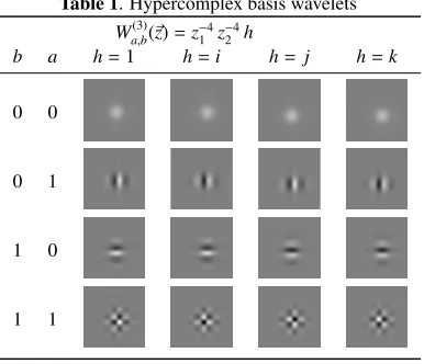
6. STEERABLE FILTERS
Table (1) shows all components of the four hypercomplex basis wavelets of the third level of the wavelet pyramid. The images were generated by composing a wavelet pyramid of zeros with a single hypercomplex impulse (for exampleWa(3),b(z)=z−4
1 z
−4
2 j)
[image:4.595.302.522.123.311.2]where (−4,−4) is next to the centre of the pyramid).
Table 1. Hypercomplex basis wavelets
Wa(3),b(z)=z
−4
1 z
−4
2 h
b a h=1 h=i h= j h=k
0 0
0 1
1 0
1 1
We can pool the four hypercomplex coefficients for a linear combination of the four basis wavelets shown in table 1 as a 2×2 matrix so thatWa(3),b=z−4
1 z
−4
2 va,b
V=
v0,0 v0,1
v1,0 v1,1
,V ∈HCA2×2
2 (10)
One can see in table 1 that the low-frequency wavelets have a pattern which has half the frequency of its high-frequency sib-ling. If we take this into account, we can model small translations of the texture defined byVas follows
e ⎛ ⎜⎜⎜⎜ ⎜⎜⎜⎜ ⎝
2π∆y j/2 0
0 2π∆y j
⎞ ⎟⎟⎟⎟ ⎟⎟⎟⎟ ⎠
· V ·e ⎛ ⎜⎜⎜⎜ ⎜⎜⎜⎜ ⎝
2π∆x i/2 0 0 2π∆x i
⎞ ⎟⎟⎟⎟ ⎟⎟⎟⎟ ⎠
(11)
Note that this model requires a commutative algebra, i.e. this forbids the use of quaternions. The pattern is centred ifV =
A(1+i+j+k) whereAis real-valued (A ∈R2×2). Table (2)
shows the result.
One can see in table 1 that the low frequency wavelets can be used to generate a steerable gradient-like shape. Term (12) yields the rotating pattern shown in table (3)).
(1−k) cos(α)
1 0 0 0
+(i− j) sin(α)
1 0 0 0
(12)
Figure 2 shows how the frequency domain is covered by the basis wavelets. As can be observed, modelling rotations in gen-eral is much more difficult, because signal energy is transferred
Table 2. translation in x-direction (∆y=0) ∆x=0 1
6
2 6
3 6
4 6
[image:4.595.311.506.216.428.2]5 6
Table 3. rotating gradient shape
α=0 π
12
2π
12
3π
12
4π
12
5π
12
between different basis wavelets.E.g.if all signal energy is con-centrated inv0,1and in the first quadrant (see figure 2), a rotation
of π2−ρ(whereρ≔sin−1(1
3), see figure 2) will transfer all
en-ergy tov1,0. A solution to this problem is to use polar separable
v
1
,
0
v
1
,
1
[image:4.595.70.263.315.481.2]v
0
,
1
ρ
Figure 2. Basis wavelets of different scale covering the first quadrant of the frequency domain
filters as in [9]. However this approach does not allow to model the translations as shown above.
However using linear combinations of the basis wavelets (see table 1) one can approximate rotating patterns. Using the term (13), table (4) was generated.
(1+k) cos(α+ρ)
0 1
0 0
+(i+j) cos(α−ρ)
0 1 0 0
+
(1+k) sin(α+ρ)
0 0 1 0
+(i+j) sin(α−ρ)
0 0 1 0
+
1
2(1−i) sin(α)
0 0 0 1
+1
2(1−j) cos(α)
0 0 0 1
[image:4.595.349.463.506.607.2]
Table 4. rotating gradient shape
α=0 π
12
2π
12
3π
12
4π
12
5π
12
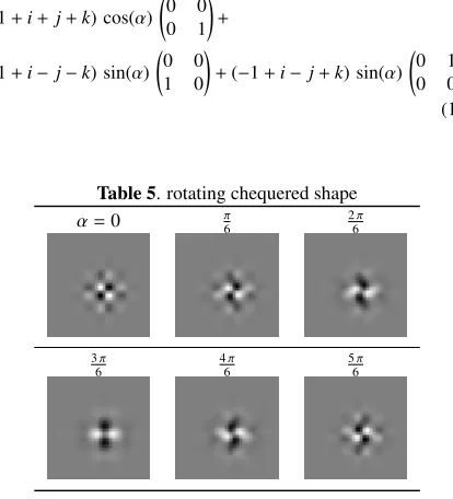
Term (14) generates a rotating chequered shape (see table (5). One can see that the outer fringes of the filter are not participating in the rotation of the pattern.
(1+i+j+k) cos(α)
0 0 0 1
+
(1+i−j−k) sin(α)
0 0 1 0
+(−1+i− j+k) sin(α)
0 1 0 0
(14)
Table 5. rotating chequered shape
α=0 π6 2π
6
3π
6
4π
6
5π
6
Using the addition theorems, terms (12), (13), and (14) each can be brought into the following form which represents a steer-able filter
cos(α)H1+sin(α)H2,whereH1,H2∈HCA2×2 (15)
7. CONCLUSION
A complete implementation of Kingsbury’s dual-tree hypercom-plex wavelet transform including Selesnick’s filter design has been given. A fully functional program for manipulating arrays of hypercomplex numbers in Ruby was implemented. The pro-gram then was optimised by adding native methods for element-wise operations into this framework. This concept allows real-time performance to be achieved without sacrificing the flexibil-ity of the datastructures in use. The implementation is available for free on the Nanorobotics website1under the terms and
con-ditions of the GPL. Our implementation does not rely on
propri-1http://vision.eng.shu.ac.uk/mmvlwiki/index.php/Nanorobotics
etary software and therefore can potentially be integrated into an embedded platform.
It has been shown, how the basis wavelets can be used to model translation of patterns. Furthermore three patterns have been presented which allow approximate rotations as well. Fu-ture work will attempt to model rotating patterns more accu-rately. The motivation is to be able to represent arbitrary texture patches as a linear combination of steerable wavelets which can be steered both in rotation as well as translation. If such a wavelet basis exists, it would be possible to model arbitrary translations and rotations as operations in the hypercomplex domain. A fea-ture extraction method based on this model would then be able to pick out salient features (e.g. edges, corners, and joints) and recover them regardless of rotation, translation, and scale.
Furthermore we would like to point out that the redundancy of the dual-tree complex wavelet transform can be overcome by using the softy-space projection[10] which relieves the redun-dancy by projecting the real-valued image on a hypercomplex image of lower resolution.
8. REFERENCES
[1] I. W. Selesnick, R. G. Baraniuk, and N. C. Kingsbury, “The dual-tree complex wavelet transform,” IEEE Signal Pro-cessing Magazine, vol. 22, no. 6, pp. 123–51, Nov. 2005.
[2] T. B¨ulow, Hypercomplex Spectral Signal Representations for Image Processing and Analysis, Ph.D. thesis, Christian-Albrechts-Universit¨at, Kiel, Germany, 1999.
[3] I. W. Selesnick and K. Y. Li, “Video denoising using 2d and 3d dual-tree complex wavelet transforms,” inWavelets: application in Signal and Image Processing X, Nov. 2003, vol. 5207, pp. 607–18.
[4] I. W. Selesnick, “The design of approximate Hilbert trans-form pairs of wavelet bases,”IEEE Transactions on Signal Processing, vol. 50, no. 5, pp. 1144–52, May 2002.
[5] W. H. Press, S. A. Teukolsky, W. T. Vetterling, and B. P. Flannery, Numerical Recipes in C: the Art of Scientific Computing, Cambridge University Press, 1992.
[6] R. M. Corless, M. W. Giesbrecht, M. van Hoeij, I. S. Kot-sireas, and S. M. Watt, “Towards factoring bivariate ap-proximate polynomials,” in Proceedings of 2001 Inter-national Symposium on Symbolic and Algebraic Computa-tion, July 2001, pp. 85–92.
[7] N. Kingsbury, “Complex wavelets for shift invariant anal-ysis and filtering of signals,” Applied and Computational Harmonic Analysis, vol. 10, no. 3, pp. 234–253, 2001, Jour-nal.
[8] A. Gurtovoy and D. Abrahams, “The boost c++ metaprogramming library,” Tech. Rep., Mar. 2002, http://www.boost.org/libs/mpl/doc/paper/mpl paper.pdf.
[9] Anil Anthony Bharath and Jeffrey Ng, “A steerable com-plex wavelet construction and its application to image de-noising,”IEEE Transactions on Image Processing, vol. 14, pp. 948–959, 2005.
[10] F. C. A. Fernandes, I. W. Selesnick, R. L. C. van Spaen-donck, and C. S. Burrus, “Complex wavelet transforms with allpass filters,” Signal Processing, vol. 83, pp. 1689– 706, Aug. 2003, Elsevier International Journal.
[image:5.595.62.269.339.567.2]